Page 778 of 2870

PM-41
PERIODIC MAINTENANCE SERVICE
Steering System (Power Steering)
26.Steering System (Power
Steering)
A: INSPECTION
1. STEERING WHEEL
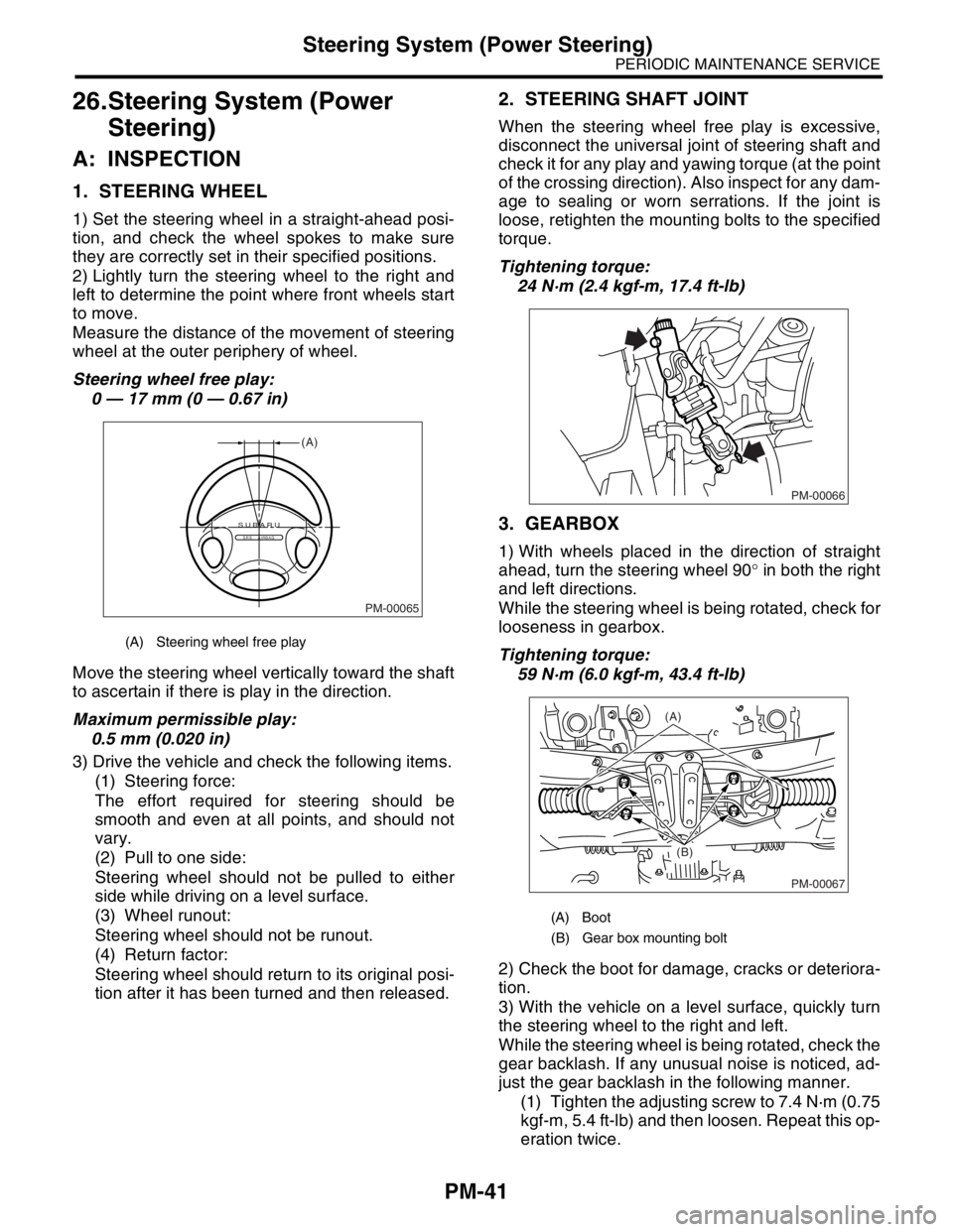
1) Set the steering wheel in a straight-ahead posi-
tion, and check the wheel spokes to make sure
they are correctly set in their specified positions.
2) Lightly turn the steering wheel to the right and
left to determine the point where front wheels start
to move.
Measure the distance of the movement of steering
wheel at the outer periphery of wheel.
Steering wheel free play:
0 — 17 mm (0 — 0.67 in)
Move the steering wheel vertically toward the shaft
to ascertain if there is play in the direction.
Maximum permissible play:
0.5 mm (0.020 in)
3) Drive the vehicle and check the following items.
(1) Steering force:
The effort required for steering should be
smooth and even at all points, and should not
vary.
(2) Pull to one side:
Steering wheel should not be pulled to either
side while driving on a level surface.
(3) Wheel runout:
Steering wheel should not be runout.
(4) Return factor:
Steering wheel should return to its original posi-
tion after it has been turned and then released.
2. STEERING SHAFT JOINT
When the steering wheel free play is excessive,
disconnect the universal joint of steering shaft and
check it for any play and yawing torque (at the point
of the crossing direction). Also inspect for any dam-
age to sealing or worn serrations. If the joint is
loose, retighten the mounting bolts to the specified
torque.
Tightening torque:
24 N·m (2.4 kgf-m, 17.4 ft-lb)
3. GEARBOX
1) With wheels placed in the direction of straight
ahead, turn the steering wheel 90° in both the right
and left directions.
While the steering wheel is being rotated, check for
looseness in gearbox.
Tightening torque:
59 N·m (6.0 kgf-m, 43.4 ft-lb)
2) Check the boot for damage, cracks or deteriora-
tion.
3) With the vehicle on a level surface, quickly turn
the steering wheel to the right and left.
While the steering wheel is being rotated, check the
gear backlash. If any unusual noise is noticed, ad-
just the gear backlash in the following manner.
(1) Tighten the adjusting screw to 7.4 N·m (0.75
kgf-m, 5.4 ft-lb) and then loosen. Repeat this op-
eration twice.
(A) Steering wheel free play
PM-00065
(A)
SUBARUSRS AIRBAG
(A) Boot
(B) Gear box mounting bolt
PM-00066
PM-00067
(A)
(B)
Page 1137 of 2870

EN(H4SO)-39
ENGINE (DIAGNOSTIC)
Inspection Mode
1. PREPARATION FOR THE INSPECTION
MODE
1) Check battery voltage is more than 12 V and fuel
remains half [20 — 402 (5.3 — 10.6 US gal, 4.4 —
8.8 Imp gal)].
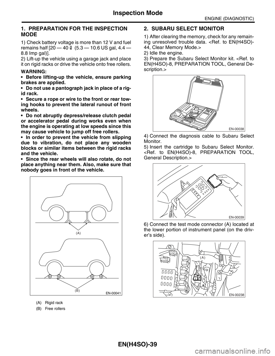
2) Lift-up the vehicle using a garage jack and place
it on rigid racks or drive the vehicle onto free rollers.
WARNING:
Before lifting-up the vehicle, ensure parking
brakes are applied.
Do not use a pantograph jack in place of a rig-
id rack.
Secure a rope or wire to the front or rear tow-
ing hooks to prevent the lateral runout of front
wheels.
Do not abruptly depress/release clutch pedal
or accelerator pedal during works even when
the engine is operating at low speeds since this
may cause vehicle to jump off free rollers.
In order to prevent the vehicle from slipping
due to vibration, do not place any wooden
blocks or similar items between the rigid racks
and the vehicle.
Since the rear wheels will also rotate, do not
place anything near them. Also, make sure that
nobody goes in front of the vehicle.
2. SUBARU SELECT MONITOR
1) After clearing the memory, check for any remain-
ing unresolved trouble data.
44, Clear Memory Mode.>
2) Idle the engine.
3) Prepare the Subaru Select Monitor kit.
EN(H4SO)-8, PREPARATION TOOL, General De-
scription.>
4) Connect the diagnosis cable to Subaru Select
Monitor.
5) Insert the cartridge to Subaru Select Monitor.
General Description.>
6) Connect the test mode connector (A) located at
the lower portion of instrument panel (on the driv-
er’s side).
(A) Rigid rack
(B) Free rollers
EN-00041
(A)
(B)
EN-00038
EN-00039
EN-00238
(A)
Page 1672 of 2870

EN(H4DOTC)-42
ENGINE (DIAGNOSTIC)
Inspection Mode
1. PREPARATION FOR THE INSPECTION
MODE
1) Check battery voltage is more than 12 V and fuel
remains half [20 to 402 (5.3 to 10.6 US gal, 4.4 to
8.8 Imp gal)].
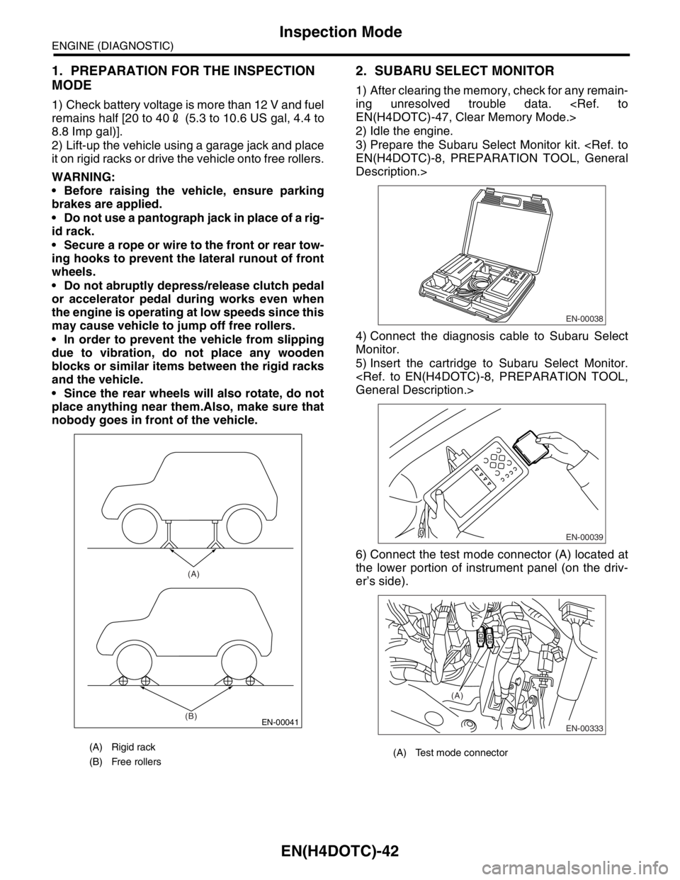
2) Lift-up the vehicle using a garage jack and place
it on rigid racks or drive the vehicle onto free rollers.
WARNING:
Before raising the vehicle, ensure parking
brakes are applied.
Do not use a pantograph jack in place of a rig-
id rack.
Secure a rope or wire to the front or rear tow-
ing hooks to prevent the lateral runout of front
wheels.
Do not abruptly depress/release clutch pedal
or accelerator pedal during works even when
the engine is operating at low speeds since this
may cause vehicle to jump off free rollers.
In order to prevent the vehicle from slipping
due to vibration, do not place any wooden
blocks or similar items between the rigid racks
and the vehicle.
Since the rear wheels will also rotate, do not
place anything near them.Also, make sure that
nobody goes in front of the vehicle.
2. SUBARU SELECT MONITOR
1) After clearing the memory, check for any remain-
ing unresolved trouble data.
EN(H4DOTC)-47, Clear Memory Mode.>
2) Idle the engine.
3) Prepare the Subaru Select Monitor kit.
EN(H4DOTC)-8, PREPARATION TOOL, General
Description.>
4) Connect the diagnosis cable to Subaru Select
Monitor.
5) Insert the cartridge to Subaru Select Monitor.
General Description.>
6) Connect the test mode connector (A) located at
the lower portion of instrument panel (on the driv-
er’s side).
(A) Rigid rack
(B) Free rollers
EN-00041
(A)
(B)
(A) Test mode connector
EN-00038
EN-00039
EN-00333
(A)
Page 2061 of 2870

EN(H4DOTC 2.5)-37
ENGINE (DIAGNOSTIC)
Inspection Mode
1. PREPARATION FOR THE INSPECTION
MODE
1) Check battery voltage is more than 12 V and fuel
remains half [20 — 402 (5.3 — 10.6 US gal, 4.4 —
8.8 Imp gal)].
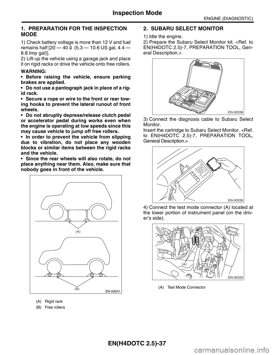
2) Lift-up the vehicle using a garage jack and place
it on rigid racks or drive the vehicle onto free rollers.
WARNING:
Before raising the vehicle, ensure parking
brakes are applied.
Do not use a pantograph jack in place of a rig-
id rack.
Secure a rope or wire to the front or rear tow-
ing hooks to prevent the lateral runout of front
wheels.
Do not abruptly depress/release clutch pedal
or accelerator pedal during works even when
the engine is operating at low speeds since this
may cause vehicle to jump off free rollers.
In order to prevent the vehicle from slipping
due to vibration, do not place any wooden
blocks or similar items between the rigid racks
and the vehicle.
Since the rear wheels will also rotate, do not
place anything near them. Also, make sure that
nobody goes in front of the vehicle.
2. SUBARU SELECT MONITOR
1) Idle the engine.
2) Prepare the Subaru Select Monitor kit.
EN(H4DOTC 2.5)-7, PREPARATION TOOL, Gen-
eral Description.>
3) Connect the diagnosis cable to Subaru Select
Monitor.
Insert the cartridge to Subaru Select Monitor.
to EN(H4DOTC 2.5)-7, PREPARATION TOOL,
General Description.>
4) Connect the test mode connector (A) located at
the lower portion of instrument panel (on the driv-
er’s side).
(A) Rigid rack
(B) Free rollers
EN-00041
(A)
(B)
(A) Test Mode Connector
EN-00038
EN-00039
EN-00333
(A)