2004 SUBARU FORESTER radio antenna
[x] Cancel search: radio antennaPage 311 of 2870

ENTERTAINMENT
ET
Page
1. General Description ....................................................................................2
2. Radio System ..............................................................................................3
3. Front Accessory Power Supply Socket System ..........................................4
4. Radio Body..................................................................................................5
5. Front Speaker .............................................................................................6
6. Antenna .......................................................................................................7
7. Antenna Amplifier ........................................................................................8
8. Front Accessory Power Supply Socket .......................................................9
Page 312 of 2870

ET-2
ENTERTAINMENT
General Description
1. General Description
A: CAUTION
Before disassembling or reassembling parts, al-
ways disconnect the battery ground cable. When re-
placing radio, control module and other parts
provided with memory functions, record memory con-
tents before disconnecting the battery ground cable.
Otherwise, the memory will be erased.
Reassemble in reverse order of disassembly, un-
less otherwise indicated.
Adjust parts to the given specifications.
Connect the connectors and hoses securely dur-
ing reassembly.
After reassembly, make sure functional parts op-
erate smoothly.
B: PREPARATION TOOL
1. GENERAL TOOL
TOOL NAME REMARKS
Circuit tester Used for measuring resis-
tance and voltage.
Conductive silver composi-
tion
(DUPONT No. 4817 or
equivalent)Used for repairing antenna
wire.
Page 313 of 2870

ET-3
ENTERTAINMENT
Radio System
2. Radio System
A: WIRING DIAGRAM
1. RADIO
B: INSPECTION
Symptom Repair order
No power coming in. (No display and no sound from speakers.) (1) Check the fuse and power supply for radio.
(2) Check the radio ground.
(3) Remove the radio for repair.
A specific speaker does not operate. (1) Check the speaker.
(2) Check the output circuit between radio and speaker.
Radio generates noise with engine running. (1) Check the radio ground.
(2) Check the generator.
(3) Check the ignition coil.
(4) Remove the radio for repair.
AM and FM modes are weak or noisy. (1) Check the antenna.
(2) Check the antenna amplifier.
(3) Check the noise suppressor.
(4) Check the radio ground.
(5) Remove the radio for repair.
Page 315 of 2870
ET-5
ENTERTAINMENT
Radio Body
4. Radio Body
A: REMOVAL
1) Disconnect the ground cable from battery.
2) Remove the front cover.
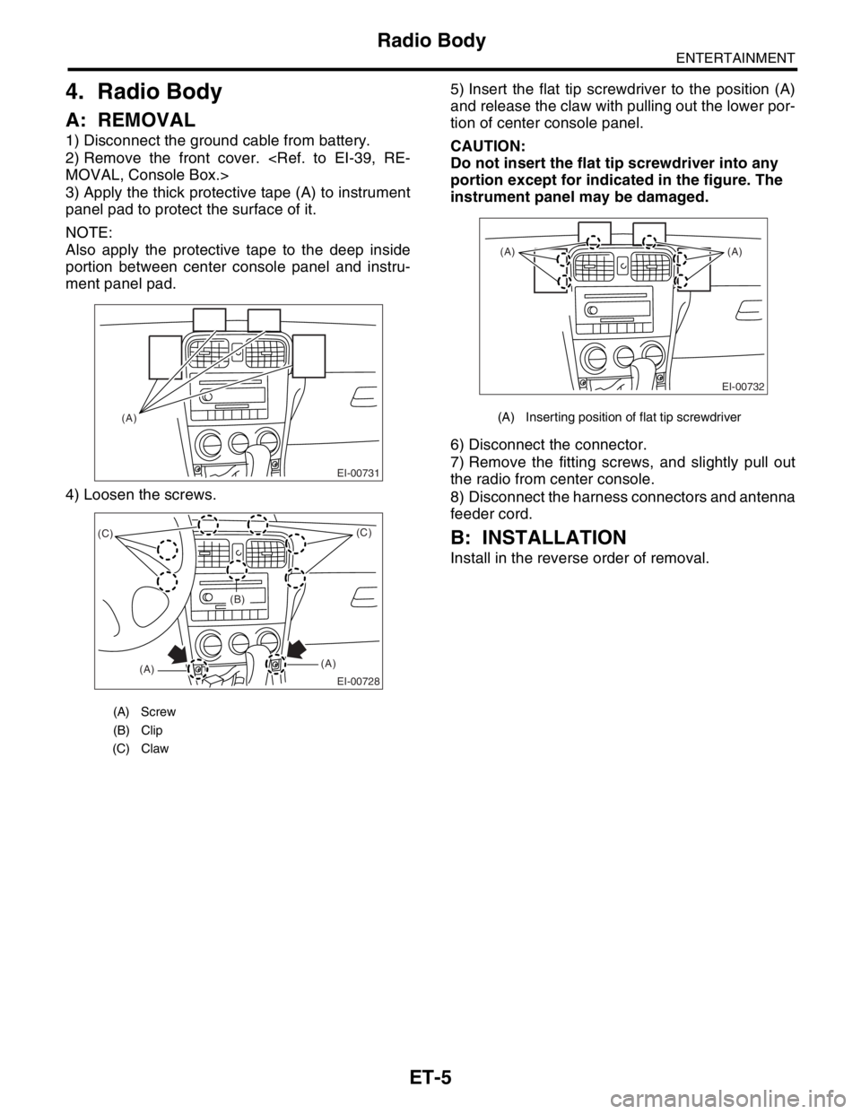
3) Apply the thick protective tape (A) to instrument
panel pad to protect the surface of it.
NOTE:
Also apply the protective tape to the deep inside
portion between center console panel and instru-
ment panel pad.
4) Loosen the screws.5) Insert the flat tip screwdriver to the position (A)
and release the claw with pulling out the lower por-
tion of center console panel.
CAUTION:
Do not insert the flat tip screwdriver into any
portion except for indicated in the figure. The
instrument panel may be damaged.
6) Disconnect the connector.
7) Remove the fitting screws, and slightly pull out
the radio from center console.
8) Disconnect the harness connectors and antenna
feeder cord.
B: INSTALLATION
Install in the reverse order of removal.
(A) Screw
(B) Clip
(C) Claw
EI-00731
(A)
EI-00728
(C)
(A)(A)(C)
(B)
(A) Inserting position of flat tip screwdriver
EI-00732
(A) (A)
Page 1104 of 2870
EN(H4SO)-6
ENGINE (DIAGNOSTIC)
General Description
3. General Description
A: CAUTION
1) Airbag system wiring harness is routed near the
ECM, main relay and fuel pump relay.
CAUTION:
All air bag system wiring harnesses and con-
nectors are yellow. Do not use the electrical
test equipment on these circuits.
Be careful not to damage the Airbag system
wiring harness when servicing the ECM, TCM,
main relay and fuel pump relay.
2) Never connect the battery in reverse polarity.
The ECM will be destroyed immediately.
The fuel injector and other part will be damaged.
3) Do not disconnect the battery terminals while the
engine is running.
A large counter electromotive force will be generat-
ed in the generator, and this voltage may damage
electronic parts such as ECM, etc.
4) Before disconnecting the connectors of each
sensor and the ECM, be sure to turn the ignition
switch to OFF.
5) Poor contact has been identified as a primary
cause of this problem. Measure the voltage or re-
sistance of individual sensor or all electrical control
modules using a tapered pin with a diameter of less
than 0.64 mm (0.025 in). Do not insert the pin more
than 5 mm (0.20 in) into the part.
6) Remove the ECM from the located position after
disconnecting two cables on battery.
Otherwise, the ECM may be damaged.
CAUTION:
When replacing the ECM, be careful not to use
the wrong spec. ECM to avoid any damage on
the fuel injection system.
7) Connectors to each sensor in the engine com-
partment and the harness connectors on the en-
gine side and body side are all designed to be
waterproof. However, it is still necessary to take
care not to allow water to get into the connectors
when washing the vehicle, or when servicing the
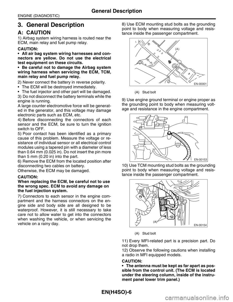
vehicle on a rainy day.8) Use ECM mounting stud bolts as the grounding
point to body when measuring voltage and resis-
tance inside the passenger compartment.
9) Use engine ground terminal or engine proper as
the grounding point to body when measuring volt-
age and resistance in the engine compartment.
10) Use TCM mounting stud bolts as the grounding
point to body when measuring voltage and resis-
tance inside the passenger compartment.
11) Every MFI-related part is a precision part. Do
not drop them.
12) Observe the following cautions when installing
a radio in MFI equipped models.
CAUTION:
The antenna must be kept as far apart as pos-
sible from the control unit. (The ECM is located
under the steering column, inside of the instru-
ment panel lower trim panel.)
(A) Stud bolt
(A) Stud bolt
EN-00001
(A)
EN-00153
EN-00154(A)
Page 1105 of 2870
EN(H4SO)-7
ENGINE (DIAGNOSTIC)
General Description
The antenna feeder must be placed as far
apart as possible from the ECM and MFI har-
ness.
Carefully adjust the antenna for correct
matching.
When mounting a large power type radio, pay
special attention to the three items above men-
tioned.
Incorrect installation of the radio may affect
the operation of the ECM.
13) Before disconnecting the fuel hose, disconnect
the fuel pump connector and crank the engine for
more than five seconds to release pressure in the
fuel system. If engine starts during this operation,
run it until it stops.
14) Problems in the electronic-controlled automatic
transmission may be caused by failure of the en-
gine, the electronic control system, the transmis-
sion proper, or by a combination of these. These
three causes must be distinguished clearly when
performing diagnostics.
15) Diagnostics should be conducted by rotating
with simple, easy operations and proceeding to
complicated, difficult operations. The most impor-
tant thing in diagnostics is to understand the cus-
tomer’s complaint, and distinguish between the
three causes.
16) In AT models, do not continue the stall for more
than five seconds. (from closed throttle, fully open
throttle to stall engine speed.)
17) On the model with ABS, when performing driv-
ing test in jacked-up or lifted-up position, some-
times the warning light may be lit, but this is not a
malfunction of the system. The reason for this is the
speed difference between the front and rear
wheels. After diagnosis of engine control system,
perform the ABS memory clearance procedure of
self-diagnosis function.
B: INSPECTION
Before performing diagnostics, check the following
items which might affect engine problems:
1. BATTERY
1) Measure battery voltage and specific gravity of
electrolyte.
Standard voltage: 12 V
Specific gravity: Above 1.260
2) Check the condition of the main and other fuses,
and harnesses and connectors. Also check for
proper grounding.
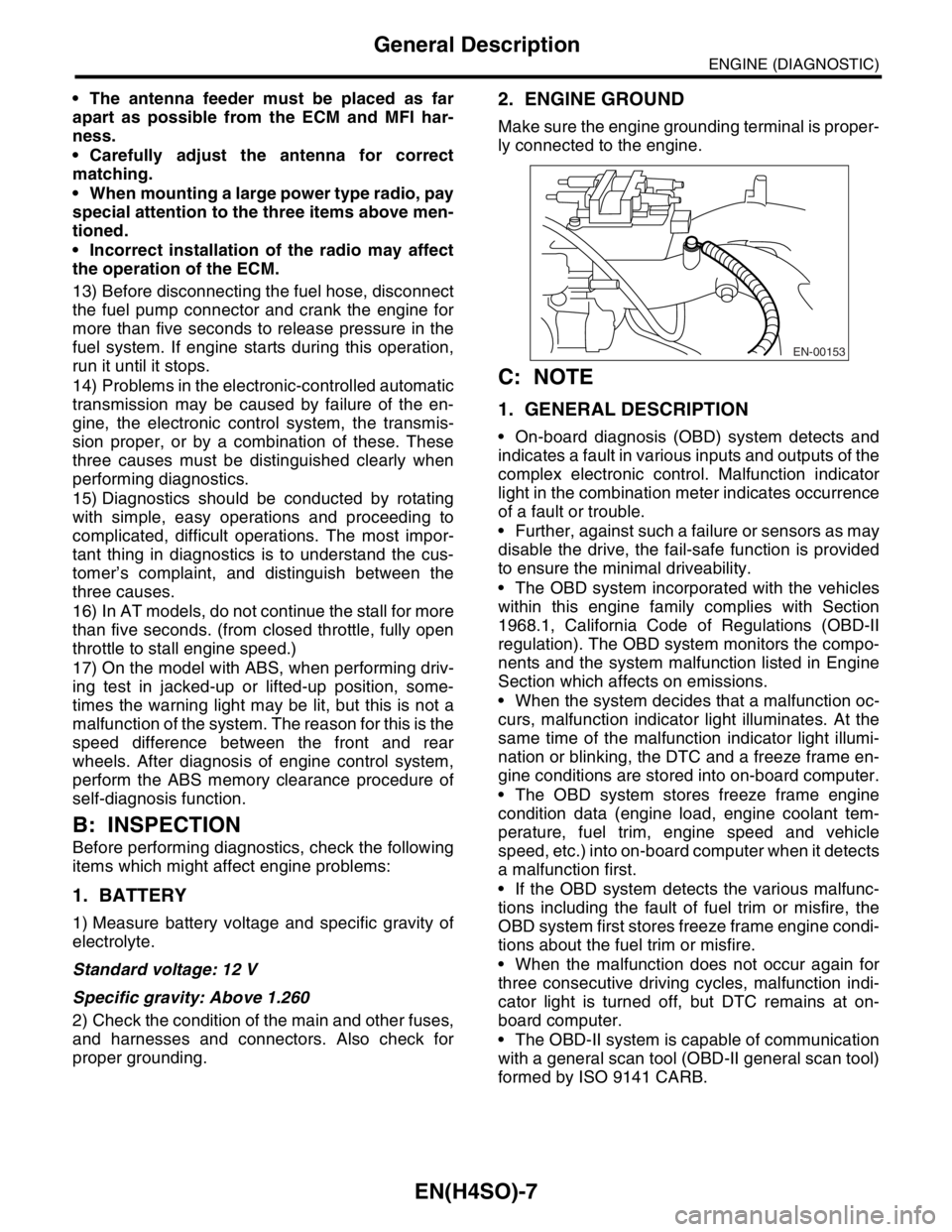
2. ENGINE GROUND
Make sure the engine grounding terminal is proper-
ly connected to the engine.
C: NOTE
1. GENERAL DESCRIPTION
On-board diagnosis (OBD) system detects and
indicates a fault in various inputs and outputs of the
complex electronic control. Malfunction indicator
light in the combination meter indicates occurrence
of a fault or trouble.
Further, against such a failure or sensors as may
disable the drive, the fail-safe function is provided
to ensure the minimal driveability.
The OBD system incorporated with the vehicles
within this engine family complies with Section
1968.1, California Code of Regulations (OBD-II
regulation). The OBD system monitors the compo-
nents and the system malfunction listed in Engine
Section which affects on emissions.
When the system decides that a malfunction oc-
curs, malfunction indicator light illuminates. At the
same time of the malfunction indicator light illumi-
nation or blinking, the DTC and a freeze frame en-
gine conditions are stored into on-board computer.
The OBD system stores freeze frame engine
condition data (engine load, engine coolant tem-
perature, fuel trim, engine speed and vehicle
speed, etc.) into on-board computer when it detects
a malfunction first.
If the OBD system detects the various malfunc-
tions including the fault of fuel trim or misfire, the
OBD system first stores freeze frame engine condi-
tions about the fuel trim or misfire.
When the malfunction does not occur again for
three consecutive driving cycles, malfunction indi-
cator light is turned off, but DTC remains at on-
board computer.
The OBD-II system is capable of communication
with a general scan tool (OBD-II general scan tool)
formed by ISO 9141 CARB.
EN-00153
Page 1637 of 2870
EN(H4DOTC)-7
ENGINE (DIAGNOSTIC)
General Description
12) Observe the following cautions when installing
a radio in MFI equipped models.
CAUTION:
The antenna must be kept as far apart as pos-
sible from the control unit. (The ECM is located
under the steering column, inside of the instru-
ment panel lower trim panel.)
The antenna feeder must be placed as far
apart as possible from the ECM and MFI har-
ness.
Carefully adjust the antenna for correct
matching.
When mounting a large power type radio, pay
special attention to the three items above men-
tioned.
Incorrect installation of the radio may affect
the operation of the ECM.
13) Before disconnecting the fuel hose, disconnect
the fuel pump connector and crank the engine for
more than five seconds to release pressure in the
fuel system.If engine starts during this operation,
run it until it stops.
14) Problems in the electronic-controlled automatic
transmission may be caused by failure of the en-
gine, the electronic control system, the transmis-
sion proper, or by a combination of these.These
three causes (engine, electronic control system,
transmission) must be distinguished clearly when
performing diagnostics.
15) Diagnostics should be conducted by rotating
with simple, easy operations and proceeding to
complicated, difficult operations.The most impor-
tant thing in diagnostics is to understand the cus-
tomer’s complaint, and distinguish between the
three causes.
16) On the model with ABS, when performing driv-
ing test in jacked-up or lifted-up position, some-
times the warning light may be lit, but this is not a
malfunction of the system.The reason for this is the
speed difference between the front and rear
wheels.After diagnosis of engine control system,
perform the ABS memory clearance procedure of
self-diagnosis function.
B: INSPECTION
Before performing diagnostics, check the following
items which might affect engine problems:
1. BATTERY
1) Measure battery voltage and specific gravity of
electrolyte.
Standard voltage: 12 V
Specific gravity: Above 1.2602) Check the condition of the main and other fuses,
and harnesses and connectors.Also check for
proper grounding.
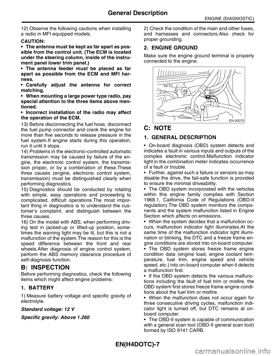
2. ENGINE GROUND
Make sure the engine ground terminal is properly
connected to the engine.
C: NOTE
1. GENERAL DESCRIPTION
On-board diagnosis (OBD) system detects and
indicates a fault in various inputs and outputs of the
complex electronic control.Malfunction indicator
light in the combination meter indicates occurrence
of a fault or trouble.
Further, against such a failure or sensors as may
disable the drive, the fail-safe function is provided
to ensure the minimal driveability.
The OBD system incorporated with the vehicles
within this engine family complies with Section
1968.1, California Code of Regulations (OBD-II
regulation).The OBD system monitors the compo-
nents and the system malfunction listed in Engine
Section which affects on emissions.
When the system decides that a malfunction oc-
curs, malfunction indicator light illuminates.At the
same time of the malfunction indicator light illumi-
nation or blinking, the DTC and a freeze frame en-
gine conditions are stored into on-board computer.
The OBD system stores freeze frame engine
condition data (engine load, engine coolant tem-
perature, fuel trim, engine speed and vehicle
speed, etc.) into on-board computer when it detects
a malfunction first.
If the OBD system detects the various malfunc-
tions including the fault of fuel trim or misfire, the
OBD system first stores freeze frame engine condi-
tions about the fuel trim or misfire.
When the malfunction does not occur again for
three consecutive driving cycles, malfunction indi-
cator light is turned off, but DTC remains at on-
board computer.
The OBD-II system is capable of communication
with a general scan tool (OBD-II general scan tool)
formed by ISO 9141 CARB.
EN-00070
Page 2029 of 2870
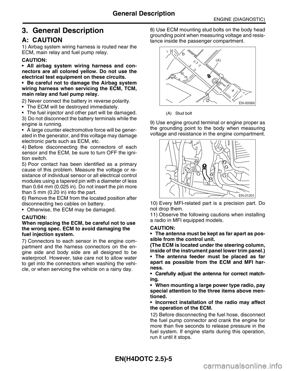
EN(H4DOTC 2.5)-5
ENGINE (DIAGNOSTIC)
General Description
3. General Description
A: CAUTION
1) Airbag system wiring harness is routed near the
ECM, main relay and fuel pump relay.
CAUTION:
All airbag system wiring harness and con-
nectors are all colored yellow. Do not use the
electrical test equipment on these circuits.
Be careful not to damage the Airbag system
wiring harness when servicing the ECM, TCM,
main relay and fuel pump relay.
2) Never connect the battery in reverse polarity.
The ECM will be destroyed immediately.
The fuel injector and other part will be damaged.
3) Do not disconnect the battery terminals while the
engine is running.
A large counter electromotive force will be gener-
ated in the generator, and this voltage may damage
electronic parts such as ECM, etc.
4) Before disconnecting the connectors of each
sensor and the ECM, be sure to turn OFF the igni-
tion switch.
5) Poor contact has been identified as a primary
cause of this problem. Measure the voltage or re-
sistance of individual sensor or all electrical control
modules using a tapered pin with a diameter of less
than 0.64 mm (0.025 in). Do not insert the pin more
than 5 mm (0.20 in) into the part.
6) Remove the ECM from the located position after
disconnecting two cables on battery.
Otherwise, the ECM may be damaged.
CAUTION:
When replacing the ECM, be careful not to use
the wrong spec. ECM to avoid damaging the
fuel injection system.
7) Connectors to each sensor in the engine com-
partment and the harness connectors on the en-
gine side and body side are all designed to be
waterproof. However, take care not to allow water
to get into the connectors when washing the vehi-
cle, or when servicing the vehicle on a rainy day. 8) Use ECM mounting stud bolts on the body head
grounding point when measuring voltage and resis-
tance inside the passenger compartment.
9) Use engine ground terminal or engine proper as
the grounding point to the body when measuring
voltage and resistance in the engine compartment.
10) Every MFI-related part is a precision part. Do
not drop them.
11) Observe the following cautions when installing
a radio in MFI equipped models.
CAUTION:
The antenna must be kept as far apart as pos-
sible from the control unit.
(The ECM is located under the steering column,
inside of the instrument panel lower trim panel.)
The antenna feeder must be placed as far
apart as possible from the ECM and MFI har-
ness.
Carefully adjust the antenna for correct match-
ing.
When mounting a large power type radio, pay
special attention to the three items above men-
tioned.
Incorrect installation of the radio may affect
the operation of the ECM.
12) Before disconnecting the fuel hose, disconnect
the fuel pump connector and crank the engine for
more than five seconds to release pressure in the
fuel system. If engine starts during this operation,
run it until it stops.
(A) Stud bolt
EN-00069
(A)
EN-01201