2004 SUBARU FORESTER turn signal bulb
[x] Cancel search: turn signal bulbPage 255 of 2870

LIGHTING SYSTEM
LI
Page
1. General Description ....................................................................................2
2. Headlight and Tail Light System .................................................................3
3. Front Fog Light System ...............................................................................4
4. Rear Fog Light System ...............................................................................5
5. Turn Signal Light and Hazard Light System................................................6
6. Back-up Light System .................................................................................7
7. Stop Light System .......................................................................................8
8. Room Light System .....................................................................................9
9. Headlight Beam Leveler System ...............................................................10
10. Combination Switch (Light) .......................................................................11
11. Headlight Assembly ..................................................................................13
12. Headlight Bulb ...........................................................................................16
13. Front Turn Signal Light Bulb .....................................................................17
14. Clearance Light Bulb .................................................................................18
15. Front Fog Light Assembly .........................................................................19
16. Front Fog Light Bulb..................................................................................20
17. Rear Combination Light Assembly ............................................................21
18. Tail/Stop Light Bulb ...................................................................................22
19. Back-up Light Bulb ....................................................................................23
20. Rear Turn Signal Light Bulb ......................................................................24
21. Rear Fog Light Bulb ..................................................................................25
22. License Plate Light ....................................................................................26
23. High-mounted Stop Light ..........................................................................27
24. Side Turn Signal Light ...............................................................................28
25. Spot Map Light ..........................................................................................29
26. Room Light ................................................................................................30
27. Luggage Room Light .................................................................................31
28. Glove Box Light .........................................................................................32
Page 260 of 2870

LI-6
LIGHTING SYSTEM
Turn Signal Light and Hazard Light System
5. Turn Signal Light and Hazard
Light System
A: WIRING DIAGRAM
1. TURN SIGNAL LIGHT AND HAZARD
LIGHT
B: INSPECTION
1. TURN SIGNAL SWITCH
2. HAZARD SWITCH
Measure the resistance between hazard switch ter-
minals.
3. TURN SIGNAL AND HAZARD MODULE
Connect the battery and the turn signal light bulb to
module, as shown in the figure. The module is
properly functioning if it blinks when power is sup-
plied to the circuit.
Switch position Terminal No. Standard
OFF 6 and 7 Less than 1 Ω
ON1, 3 and 4 Less than 1 Ω
7 and 8 Less than 1 Ω
LI-00002
43 21
5 6 7 8
LI-00003
Page 271 of 2870

LI-17
LIGHTING SYSTEM
Front Turn Signal Light Bulb
13.Front Turn Signal Light Bulb
A: REMOVAL
1) Remove the headlight assembly.
2) Turn the socket and remove the bulb.
B: INSTALLATION
Install in the reverse order of removal.
C: INSPECTION
1) Visually check the bulb for blow out.
2) Check the bulb specification.
3) If NG, replace the bulb with a new one.
LI-00021
Page 278 of 2870

LI-24
LIGHTING SYSTEM
Rear Turn Signal Light Bulb
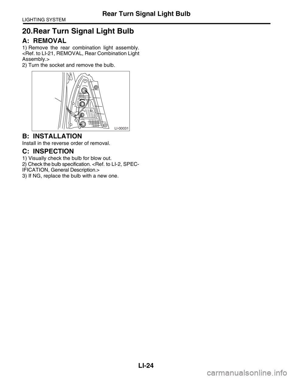
20.Rear Turn Signal Light Bulb
A: REMOVAL
1) Remove the rear combination light assembly.
2) Turn the socket and remove the bulb.
B: INSTALLATION
Install in the reverse order of removal.
C: INSPECTION
1) Visually check the bulb for blow out.
2) Check the bulb specification.
3) If NG, replace the bulb with a new one.
LI-00031
Page 282 of 2870

LI-28
LIGHTING SYSTEM
Side Turn Signal Light
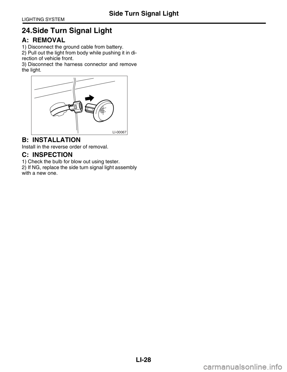
24.Side Turn Signal Light
A: REMOVAL
1) Disconnect the ground cable from battery.
2) Pull out the light from body while pushing it in di-
rection of vehicle front.
3) Disconnect the harness connector and remove
the light.
B: INSTALLATION
Install in the reverse order of removal.
C: INSPECTION
1) Check the bulb for blow out using tester.
2) If NG, replace the side turn signal light assembly
with a new one.
LI-00067
Page 396 of 2870

IDI-12
INSTRUMENTATION/DRIVER INFO
Combination Meter Assembly
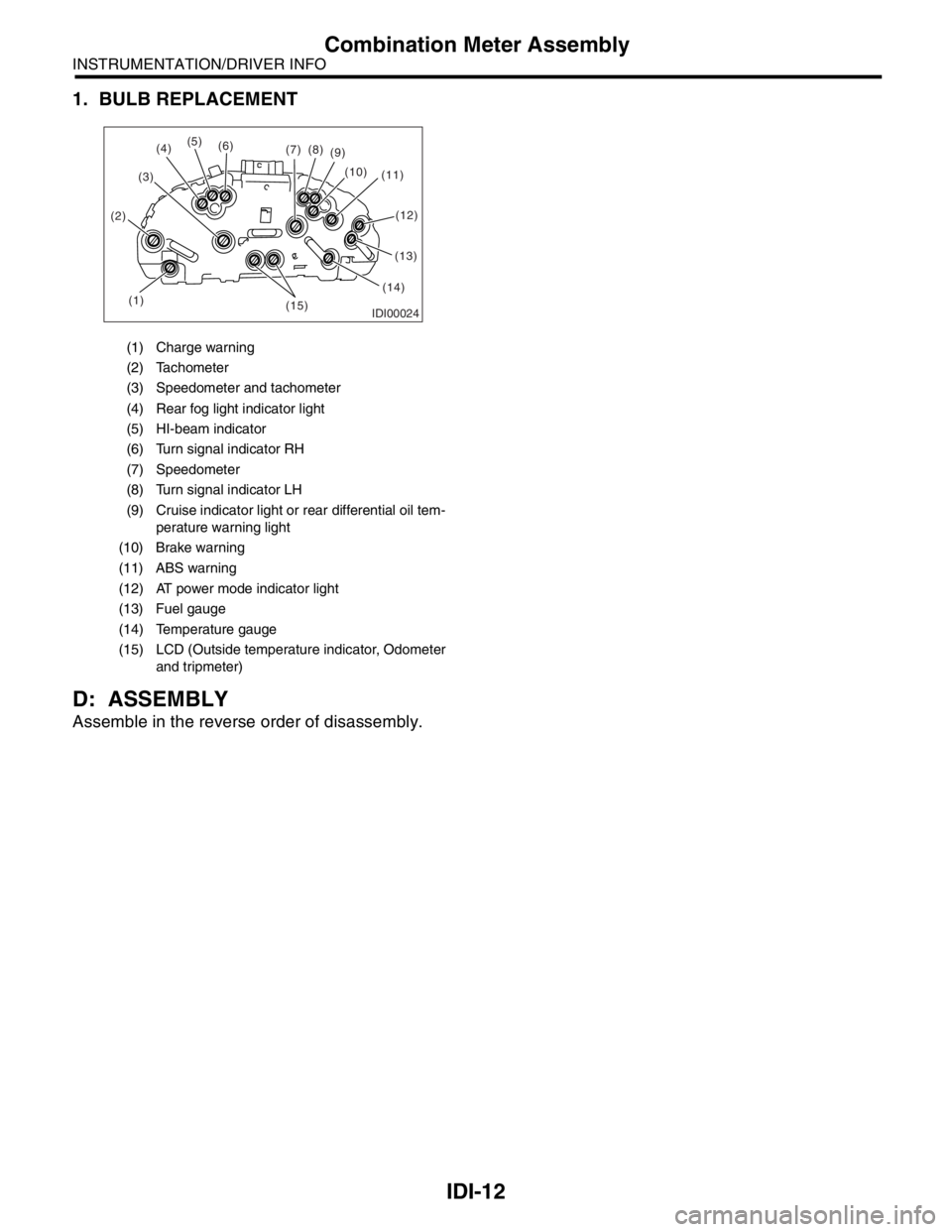
1. BULB REPLACEMENT
D: ASSEMBLY
Assemble in the reverse order of disassembly.
(1) Charge warning
(2) Tachometer
(3) Speedometer and tachometer
(4) Rear fog light indicator light
(5) HI-beam indicator
(6) Turn signal indicator RH
(7) Speedometer
(8) Turn signal indicator LH
(9) Cruise indicator light or rear differential oil tem-
perature warning light
(10) Brake warning
(11) ABS warning
(12) AT power mode indicator light
(13) Fuel gauge
(14) Temperature gauge
(15) LCD (Outside temperature indicator, Odometer
and tripmeter)
IDI00024(1) (2)(3)(5)
(6)
(7)(8)
(9)
(10)
(11)
(13)
(14)
(15)
(4)
(12)
Page 2487 of 2870

4AT(H4SO)-28
AUTOMATIC TRANSMISSION (DIAGNOSTIC)
Power Indicator Light Display
Step Check Yes No
1 CHECK POWER INDICATOR LIGHT.
Turn the ignition switch to ON (engine OFF).Does the POWER indicator
light illuminate?Go to step 3.Go to step 2.
2 CHECK POWER INDICATOR LIGHT.
1) Turn the ignition switch to OFF.
2) Remove the combination meter.
3) Remove the POWER indicator light bulb
from combination meter.Is the POWER indicator light
bulb OK?Go to step 4.Replace the
POWER indicator
light bulb.
3 CHECK POWER INDICATOR LIGHT.
Perform “Read Diagnostic Trouble Code
(DTC)”.
light blink?A temporary poor
contact of the con-
nector or harness
may be the cause.
Repair the har-
ness or connector
in TCM, inhibitor
switch and combi-
nation meter.Go to step 9.
4 CHECK FUSE (No. 14).
Remove the fuse (No. 14).Is the fuse (No. 14) blown out? Replace the fuse
(No. 14). If
replaced fuse (No.
14) is blown out
easily, repair short
circuit in harness
between fuse (No.
14) and combina-
tion meter.Go to step 5.
5 CHECK HARNESS CONNECTOR BETWEEN
COMBINATION METER AND IGNITION
SWITCH.
1) Turn the ignition switch to ON (engine
OFF).
2) Measure the voltage between combination
meter connector and chassis ground.
Connector & terminal
(i10) No. 9 (+) — Chassis ground (
−):Is the voltage more than 9 V? Go to step 6.Repair the open
circuit in harness
between combina-
tion meter and bat-
tery.
6 CHECK COMBINATION METER.
Measure the voltage between combination
meter connector and chassis ground.
Connector & terminal
(i11) No. 2 (+) — Chassis ground (
−):Is the voltage less than 9 V? Repair the combi-
nation meter.
Meter Assembly.>Go to step 7.
7 CHECK OPEN CIRCUIT OF HARNESS.
1) Turn the ignition switch to OFF.
2) Disconnect the connector from combination
meter connector.
3) Measure the resistance of harness
between combination meter.
Connector & terminal
(B56) No. 11 — (i11) No. 2:Is the resistance less than 1
Ω?Go to step 8.Repair the open
circuit in harness
between TCM and
combination
meter, and poor
contact in cou-
pling connector.
8 CHECK INPUT SIGNAL FOR TCM.
1) Connect the connector to TCM and combi-
nation meter.
2) Turn the ignition switch to ON (engine
OFF).
3) Measure the voltage between TCM con-
nector and chassis ground.
Connector & terminal
(B56) No. 11 (+) — Chassis ground (
−):Is the voltage less than 1 V? Even if the
POWER indicator
lights up, the cir-
cuit has returned
to a normal condi-
tion at this time. A
temporary poor
contact of the con-
nector or harness
may be the cause.
Repair the har-
ness or connector
in TCM.Replace the TCM.
trol Module
(TCM).>
Page 2558 of 2870

4AT(H4SO)-99
AUTOMATIC TRANSMISSION (DIAGNOSTIC)
Diagnostic Procedure without Diagnostic Trouble Code (DTC)
22 CHECK HARNESS CONNECTOR BETWEEN
INHIBITOR SWITCH AND CHASSIS
GROUND.
1) Turn the ignition switch to OFF.
2) Disconnect the connector from inhibitor
switch.
3) Measure the resistance of harness
between inhibitor switch and chassis ground.
Connector & terminal
(T7) No. 5 — Chassis ground:Is the resistance less than 1
Ω?Go to step 23.Repair the open
circuit in harness
between inhibitor
switch connector
and chassis
ground, and poor
contact in cou-
pling connector.
23 CHECK HARNESS CONNECTOR BETWEEN
TCM AND INHIBITOR SWITCH.
1) Turn the ignition switch to OFF.
2) Disconnect the connectors from TCM and
inhibitor switch.
3) Measure the resistance of harness
between TCM and inhibitor switch connector.
Connector & terminal
(B55) No. 1 — (T7) No. 9:Is the resistance less than 1
Ω?Go to step 24.Repair the open
circuit in harness
between TCM and
inhibitor switch
connector, and
poor contact in
coupling connec-
tor.
24 CHECK INPUT SIGNAL FOR TCM.
1) Turn the ignition switch to OFF.
2) Connect the connector to TCM and inhibitor
switch.
3) Turn the ignition switch to ON.
4) Move the select lever to “P” range.
5) Measure the voltage between TCM and
chassis ground.
Connector & terminal
(B55) No. 1 (+) — Chassis ground (–):Is the voltage less than 1 V? Go to step 25.Go to step 65.
25 CHECK INPUT SIGNAL FOR TCM.
1) Position the select lever to any other than
“P” range.
2) Measure the voltage between TCM and
chassis ground.
Connector & terminal
(B55) No. 1 (+) — Chassis ground (–):Is the voltage more than 8 V? Go to step 65.Replace the TCM.
trol Module
(TCM).>
26 CHECK “P” RANGE INDICATOR LIGHT
BULB.
1) Turn the ignition switch to OFF.
2) Remove the combination meter.
3) Remove the “P” range indicator light bulb
from combination meter.Is the “P” range indicator light
bulb OK?Go to step 27.Replace the “P”
range indicator
light bulb.
tion Meter Assem-
bly.>
27 CHECK HARNESS CONNECTOR BETWEEN
TCM AND COMBINATION METER.
1) Disconnect the connectors from TCM and
combination meter.
2) Measure the resistance of harness
between TCM and combination meter.
Connector & terminal
(B55) No. 1 — (i10) No. 1:Is the resistance more than 1
Ω?Go to step 65.Repair the open cir-
cuit in harness
between TCM con-
nector and combi-
nation meter, and
poor contact in cou-
pling connector.
28 CHECK HARNESS CONNECTOR BETWEEN
TCM AND INHIBITOR SWITCH.
1) Turn the ignition switch to OFF.
2) Disconnect the connectors from TCM,
inhibitor switch and combination meter.
3) Measure the resistance of harness
between TCM and chassis ground.
Connector & terminal
(B55) No. 1 — Chassis ground:Is the resistance less than 1
MΩ?Go to step 29.Repair the ground
short circuit in “P”
range circuit. Step Check Yes No