Page 34 of 2870
AC-32
HVAC SYSTEM (HEATER, VENTILATOR AND A/C)
Blower Motor Unit Assembly
7. Blower Motor Unit Assembly
A: REMOVAL
1) Disconnect the ground cable from battery.
2) Remove the glove box.
AL, Glove Box.>
3) Loosen the nut to remove the support beam
stay.
4) Disconnect the connectors of blower motor and
intake actuator resistor.
5) Loosen the bolt and nut to remove blower motor
unit assembly.
B: INSTALLATION
Install in the reverse order of removal.
Tightening torque:
Refer to COMPONENT in General Descrip-
tion.
COMPONENT, General Description.>
AC-9, BLOWER MOTOR UNIT, COMPONENT,
General Description.>
C: INSPECTION
Inspection of Auto A/C Brush-less Motor
Operation
Connect the motor connector terminal 1 from the
battery to the positive (+) lead and terminal 2 and 5
at the same time to the negative (−) lead. Make
sure the motor runs smoothly.
AC-00218
AC-00219
AC-00220
AC-00244
22
55
1 1
Page 41 of 2870
AC-39
HVAC SYSTEM (HEATER, VENTILATOR AND A/C)
Heater Cooling Unit
14.Heater Cooling Unit
A: REMOVAL
1) Disconnect the ground cable from battery.
2) Using the refrigerant recovery system, dis-
charge refrigerant.
Refrigerant Recovery Procedure.>
3) Drain the engine coolant from radiator.
4) Remove the bolt securing expansion valve and
pipe in engine compartment. Release the heater
hose clamps in engine compartment to remove the
hoses.
5) Remove the instrument panel.
REMOVAL, Instrument Panel Assembly.>
6) Remove the support beam.
7) Remove the blower motor unit assembly.
to AC-32, REMOVAL, Blower Motor Unit Assem-
bly.>
8) Disconnect the servo motor connectors.
9) Remove the bolt and nuts to remove the heater
and cooling unit.
B: INSTALLATION
1) Install in the reverse order of removal.
2) Charge refrigerant.
TION, Refrigerant Charging Procedure.>
Tightening torque:
Refer to COMPONENT in General Descrip-
tion.
COMPONENT, General Description.>
AC-00870
AC-00055
Page 115 of 2870

AB-15
AIRBAG SYSTEM
Passenger’s Airbag Module
5. Passenger’s Airbag Module
A: REMOVAL
CAUTION:
Refer to “CAUTION” in General Description be-
fore handing the airbag module.
CAUTION, General Description.>
1) Turn the ignition switch to OFF.
2) Disconnect the ground cable from battery, and
wait for at least 20 seconds before starting work.
3) Remove the glove box.
AL, Glove Box.>
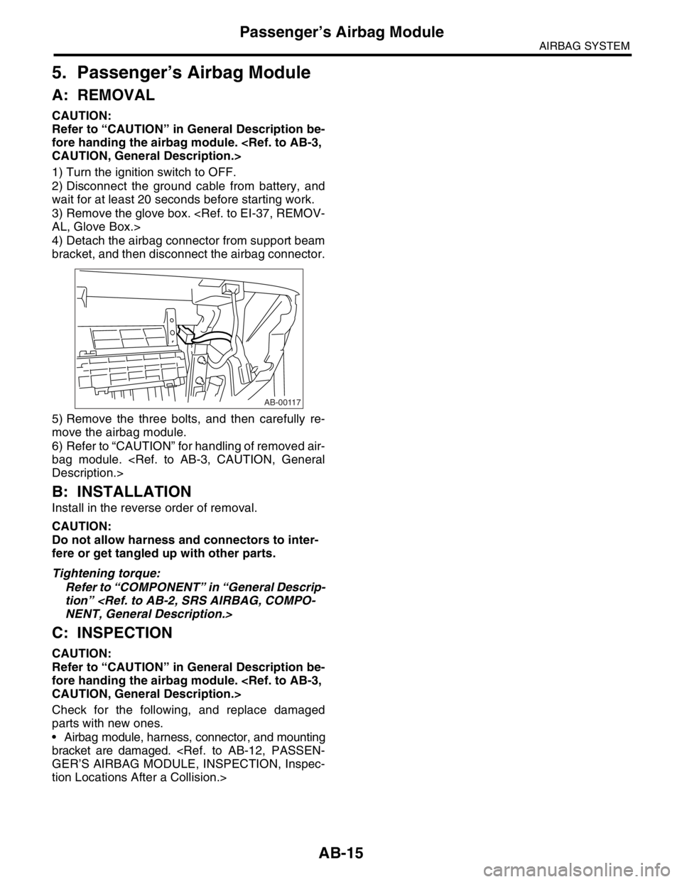
4) Detach the airbag connector from support beam
bracket, and then disconnect the airbag connector.
5) Remove the three bolts, and then carefully re-
move the airbag module.
6) Refer to “CAUTION” for handling of removed air-
bag module.
Description.>
B: INSTALLATION
Install in the reverse order of removal.
CAUTION:
Do not allow harness and connectors to inter-
fere or get tangled up with other parts.
Tightening torque:
Refer to “COMPONENT” in “General Descrip-
tion”
NENT, General Description.>
C: INSPECTION
CAUTION:
Refer to “CAUTION” in General Description be-
fore handing the airbag module.
CAUTION, General Description.>
Check for the following, and replace damaged
parts with new ones.
Airbag module, harness, connector, and mounting
bracket are damaged.
GER’S AIRBAG MODULE, INSPECTION, Inspec-
tion Locations After a Collision.>
AB-00117
Page 264 of 2870
LI-10
LIGHTING SYSTEM
Headlight Beam Leveler System
9. Headlight Beam Leveler Sys-
tem
A: WIRING DIAGRAM
1. HEADLIGHT BEAM LEVELER
Beam Leveler System.>
B: INSPECTION
1. HEADLIGHT BEAM LEVELER ACTUA-
TOR
1) Turn on the headlights.
2) Confirm the headlight beam level is lowered by
changing the switch position to 0 → 1 → 2 → 3 →
4 → 5.
2. HEADLIGHT BEAM LEVELER SWITCH
Connect the battery, headlight beam leveler switch
connector, circuit tester and resistor (470 Ω) as
shown in the figure. Measure the current at each
switch position.
Switch position Current (mA)
03.8
17.0
29.8
3 14.7
4 20.3
5 25.5
65 4 2 1
LI-00008A
RH LH
470 3
Page 266 of 2870
LI-12
LIGHTING SYSTEM
Combination Switch (Light)
2. DIMMER AND PASSING SWITCH
LHD and RHD model with rear fog light:
RHD model without rear fog light:
3. TURN SIGNAL SWITCH
LHD and RHD with rear fog light:
RHD model without rear fog light:
4. PARKING SWITCH
Switch position Terminal No. Standard
Passing 7, 8 and 16 Less than 1 Ω
Low beam 16 and 17 Less than 1 Ω
High beam 7 and 16 Less than 1 Ω
Switch position Terminal No. Standard
Passing 1, 2 and 9 Less than 1 Ω
Low beam 9 and 10 Less than 1 Ω
High beam 2 and 9 Less than 1 Ω
Switch position Terminal No. Standard
Left 1 and 2 Less than 1 Ω
Neutral — More than 1 MΩ
Right 2 and 3 Less than 1 Ω
Switch position Terminal No. Standard
Left 6 and 7 Less than 1 Ω
Neutral — More than 1 MΩ
Right 7 and 8 Less than 1 Ω
Switch position Terminal No. Standard
OFF 2 and 4 Less than 1 Ω
ON 1 and 4 Less than 1 Ω
Page 268 of 2870

LI-14
LIGHTING SYSTEM
Headlight Assembly
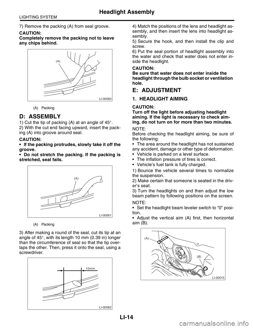
7) Remove the packing (A) from seal groove.
CAUTION:
Completely remove the packing not to leave
any chips behind.
D: ASSEMBLY
1) Cut the tip of packing (A) at an angle of 45°.
2) With the cut end facing upward, insert the pack-
ing (A) into groove around seal.
CAUTION:
If the packing protrudes, slowly take it off the
groove.
Do not stretch the packing. If the packing is
stretched, seal fails.
3) After making a round of the seal, cut its tip at an
angle of 45°, with its length 10 mm (0.39 in) longer
than the circumference of seal so that the tip over-
laps the other. Then, press it onto the seal, using a
screwdriver.4) Match the positions of the lens and headlight as-
sembly, and then insert the lens into headlight as-
sembly.
5) Secure the hook, and then install the clip and
screw.
6) Put the seal portion of headlight assembly into
the water and check that water does not enter in-
side the headlight.
CAUTION:
Be sure that water does not enter inside the
headlight through the bulb socket or ventilation
hole.
E: ADJUSTMENT
1. HEADLIGHT AIMING
CAUTION:
Turn off the light before adjusting headlight
aiming. If the light is necessary to check aim-
ing, do not turn on for more than two minutes.
NOTE:
Before checking the headlight aiming, be sure of
the following:
The area around the headlight has not sustained
any accident, damage or other type of deformation.
Vehicle is parked on a level surface.
The inflation pressure of tires is correct.
Vehicle’s fuel tank is fully charged.
1) Bounce the vehicle several times to normalize
the suspension.
2) Make certain that someone is seated in the driv-
er’s seat.
3) Turn the headlights on and then adjust the low
beam pattern by following positions on the screen.
NOTE:
Set the headlight beam leveler switch to “0” posi-
tion.
Adjust the vertical aim (A) first, then horizontal
aim (B).(A) Packing
(A) Packing
LI-00060
(A)
LI-00061
(A)
LI-00062
10mm
LI-00015
(A)
(B)
Page 372 of 2870

BS-6
BODY STRUCTURE
Datum Points
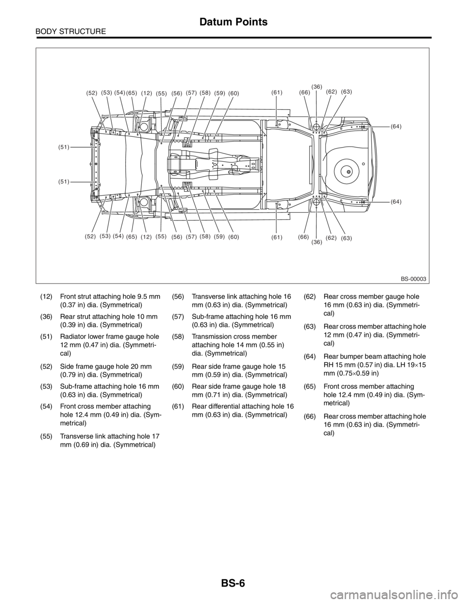
(12) Front strut attaching hole 9.5 mm
(0.37 in) dia. (Symmetrical)(56) Transverse link attaching hole 16
mm (0.63 in) dia. (Symmetrical)(62) Rear cross member gauge hole
16 mm (0.63 in) dia. (Symmetri-
cal)
(36) Rear strut attaching hole 10 mm
(0.39 in) dia. (Symmetrical)(57) Sub-frame attaching hole 16 mm
(0.63 in) dia. (Symmetrical)
(63) Rear cross member attaching hole
12 mm (0.47 in) dia. (Symmetri-
cal) (51) Radiator lower frame gauge hole
12 mm (0.47 in) dia. (Symmetri-
cal)(58) Transmission cross member
attaching hole 14 mm (0.55 in)
dia. (Symmetrical)
(64) Rear bumper beam attaching hole
RH 15 mm (0.57 in) dia. LH 19×15
mm (0.75×0.59 in) (52) Side frame gauge hole 20 mm
(0.79 in) dia. (Symmetrical)(59) Rear side frame gauge hole 15
mm (0.59 in) dia. (Symmetrical)
(53) Sub-frame attaching hole 16 mm
(0.63 in) dia. (Symmetrical)(60) Rear side frame gauge hole 18
mm (0.71 in) dia. (Symmetrical)(65) Front cross member attaching
hole 12.4 mm (0.49 in) dia. (Sym-
metrical)
(54) Front cross member attaching
hole 12.4 mm (0.49 in) dia. (Sym-
metrical)(61) Rear differential attaching hole 16
mm (0.63 in) dia. (Symmetrical)
(66) Rear cross member attaching hole
16 mm (0.63 in) dia. (Symmetri-
cal)
(55) Transverse link attaching hole 17
mm (0.69 in) dia. (Symmetrical)
BS-00003
(52)(53)(54)(65)(12)(55)(61)
(61)
(64)
(64)
(51)
(51)
(36)
(36)(66)
(66)(56)(57)(58)(59)(60)
(52)(53) (54)
(65)
(12)(55)
(56)(57)(58)
(59)
(60)(62)
(62)(63)
(63)
Page 386 of 2870

IDI-2
INSTRUMENTATION/DRIVER INFO
General Description
1. General Description
A: SPECIFICATION
B: CAUTION
Be careful not to damage meters and instrument panel.
Be careful not to damage meter glasses.
Make sure that electrical connector is connected securely.
After installation, make sure that each meter operates normally.
Use gloves to avoid damage and getting fingerprints on the glass surface and meter surfaces.
Do not apply excessive force to the printed circuit.
Do not drop or otherwise apply impact.
C: PREPARATION TOOL
1. GENERAL TOOL
Combination meterSpeedometer Electric pulse type
Temperature gauge Cross coil type
Fuel gauge Cross coil type
Tachometer Electric pulse type
Turn signal indicator light 14 V — 2 W
Charge indicator light 14 V — 1.4 W
Oil pressure indicator light LED
ABS warning light 14 V — 1.4 W
Malfunction indicator light LED
HI-beam indicator light 14 V — 2 W
Door open warning light LED
Seat belt warning light LED
Brake fluid and parking brake warning
light14 V — 2 W
FWD indicator light LED
AIRBAG warning light LED
Meter illumination light 14 V — 3.4 W, 14 V — 2 W
AT OIL TEMP. warning light LED
LO indicator light LED
HOLD indicator light LED
Immobilizer indicator light LED
Rear differential oil temperature warn-
ing light14 V — 2 W
Cruise indicator light 14 V — 1.4 W
Rear fog light indicator light 14 V — 2 W
POWER indicator light 14 V — 1.4 W
Low fuel warning light LED
AT select lever position indicator light 14 V — 100 mA
LCD back light 14 V — 1.4 W
TOOL NAME REMARKS
Circuit tester Used for measuring resistance and voltage.