2004 SUBARU FORESTER seats
[x] Cancel search: seatsPage 129 of 2870
AB-29
AIRBAG SYSTEM
Disposal of Airbag Module (Deploying After Removal from Vehicle)
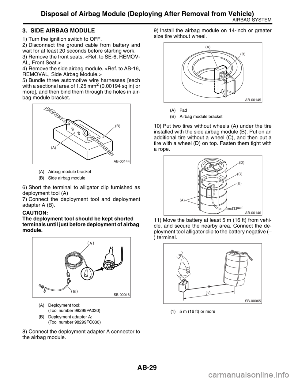
3. SIDE AIRBAG MODULE
1) Turn the ignition switch to OFF.
2) Disconnect the ground cable from battery and
wait for at least 20 seconds before starting work.
3) Remove the front seats.
4) Remove the side airbag module.
5) Bundle three automotive wire harnesses [each
with a sectional area of 1.25 mm
2 (0.00194 sq in) or
more], and then bind them through the holes in air-
bag module bracket.
6) Short the terminal to alligator clip furnished as
deployment tool (A)
7) Connect the deployment tool and deployment
adapter A (B).
CAUTION:
The deployment tool should be kept shorted
terminals until just before deployment of airbag
module.
8) Connect the deployment adapter A connector to
the airbag module.9) Install the airbag module on 14-inch or greater
size tire without wheel.
10) Put two tires without wheels (A) under the tire
installed with the side airbag module (B). Put on an
additional tire without a wheel (C), and then put a
tire with a wheel (D) on top. Fasten them tight with
a rope.
11) Move the battery at least 5 m (16 ft) from vehi-
cle, and secure the nearby area. Connect the de-
ployment tool alligator clip to the battery negative (−
) terminal.
(A) Airbag module bracket
(B) Side airbag module
(A) Deployment tool:
(Tool number 98299PA030)
(B) Deployment adapter A:
(Tool number 98299FC030)
AB-00144
(A)(B)
SB-00016
(A) Pad
(B) Airbag module bracket
(1) 5 m (16 ft) or more
AB-00145
(A)
(B)
AB-00146
(A)
(B)
(C)
(D)
SB-00065
(1)
Page 166 of 2870

AB-34
AIRBAG SYSTEM (DIAGNOSTIC)
Airbag Warning Light Failure
11.Airbag Warning Light Failure
A: AIRBAG WARNING LIGHT REMAINS ON.
DIAGNOSIS:
Airbag warning light unit is faulty.
Airbag control module to airbag warning light circuit is shorted or open.
Grounding circuit is faulty.
Airbag control module is faulty.
(AB1) and (B31) are not connected properly.
(AB3) is not connected properly to the airbag control module.
CAUTION:
Before diagnosing the airbag system, be sure to turn the ignition switch to OFF, disconnect the
ground cable from battery, and wait more than 20 seconds before starting to work.
After replacing the airbag module, seat belt pretensioner, roll connector, control module or sensor,
reconnect each part and confirm that the airbag warning light operates properly.
When inspecting the airbag main harness, disconnect the airbag module connector of the driver
and passenger seats for safety reasons.
Page 171 of 2870
AB-39
AIRBAG SYSTEM (DIAGNOSTIC)
Airbag Warning Light Failure
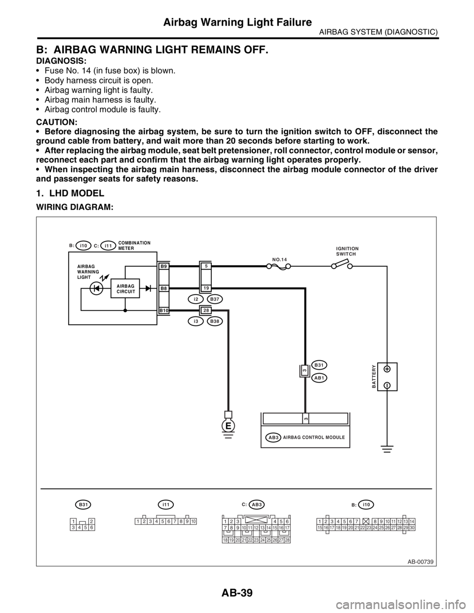
B: AIRBAG WARNING LIGHT REMAINS OFF.
DIAGNOSIS:
Fuse No. 14 (in fuse box) is blown.
Body harness circuit is open.
Airbag warning light is faulty.
Airbag main harness is faulty.
Airbag control module is faulty.
CAUTION:
Before diagnosing the airbag system, be sure to turn the ignition switch to OFF, disconnect the
ground cable from battery, and wait more than 20 seconds before starting to work.
After replacing the airbag module, seat belt pretensioner, roll connector, control module or sensor,
reconnect each part and confirm that the airbag warning light operates properly.
When inspecting the airbag main harness, disconnect the airbag module connector of the driver
and passenger seats for safety reasons.
1. LHD MODEL
WIRING DIAGRAM:
AB-00739
12
34561
2345678910123456789101112131415161718192021222324252627282930
B31 i11AB3
i10
B:
C: i10
i11
AIRBAG
WARNING
LIGHTCOMBINATION
METERB9
B8
B10
NO.14
i3B38 28
i2B37 19
5
AIRBAG CONTROL MODULEAB3
B31
AB1
3
3
AIRBAG
CIRCUIT
E
BATTERY
1234567891011121314151617
1819202122232425262728
IGNITION
SWITCH
B: C:
Page 180 of 2870
AB-48
AIRBAG SYSTEM (DIAGNOSTIC)
Diagnostic Procedure with Diagnostic Trouble Code (DTC)
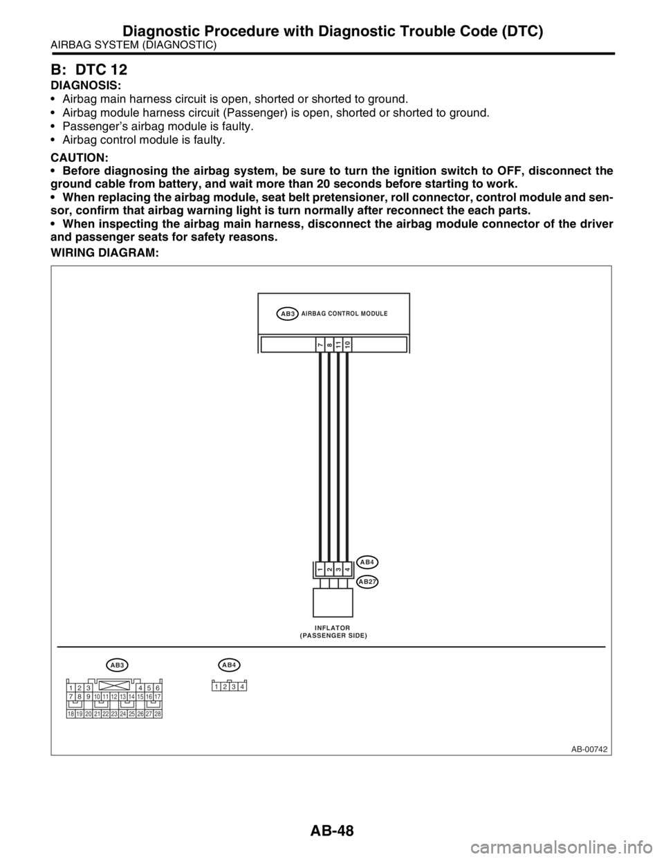
B: DTC 12
DIAGNOSIS:
Airbag main harness circuit is open, shorted or shorted to ground.
Airbag module harness circuit (Passenger) is open, shorted or shorted to ground.
Passenger’s airbag module is faulty.
Airbag control module is faulty.
CAUTION:
Before diagnosing the airbag system, be sure to turn the ignition switch to OFF, disconnect the
ground cable from battery, and wait more than 20 seconds before starting to work.
When replacing the airbag module, seat belt pretensioner, roll connector, control module and sen-
sor, confirm that airbag warning light is turn normally after reconnect the each parts.
When inspecting the airbag main harness, disconnect the airbag module connector of the driver
and passenger seats for safety reasons.
WIRING DIAGRAM:
AB-00742
AB3 INFLATOR
(PASSENGER SIDE)
AB4
AB4
AB27
11
10 3
47
8
1
2
AIRBAG CONTROL MODULEAB3
12341234567891011121314151617
1819202122232425262728
Page 184 of 2870
AB-52
AIRBAG SYSTEM (DIAGNOSTIC)
Diagnostic Procedure with Diagnostic Trouble Code (DTC)
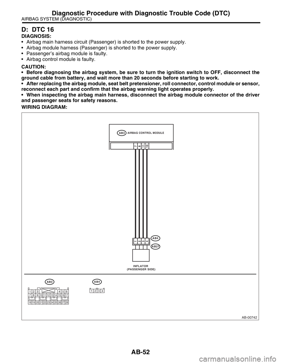
D: DTC 16
DIAGNOSIS:
Airbag main harness circuit (Passenger) is shorted to the power supply.
Airbag module harness (Passenger) is shorted to the power supply.
Passenger’s airbag module is faulty.
Airbag control module is faulty.
CAUTION:
Before diagnosing the airbag system, be sure to turn the ignition switch to OFF, disconnect the
ground cable from battery, and wait more than 20 seconds before starting to work.
After replacing the airbag module, seat belt pretensioner, roll connector, control module or sensor,
reconnect each part and confirm that the airbag warning light operates properly.
When inspecting the airbag main harness, disconnect the airbag module connector of the driver
and passenger seats for safety reasons.
WIRING DIAGRAM:
AB-00742
AB3 INFLATOR
(PASSENGER SIDE)
AB4
AB4
AB27
11
10 3
47
8
1
2
AIRBAG CONTROL MODULEAB3
12341234567891011121314151617
1819202122232425262728
Page 525 of 2870
EI-49
EXTERIOR/INTERIOR TRIM
Floor Mat
23.Floor Mat
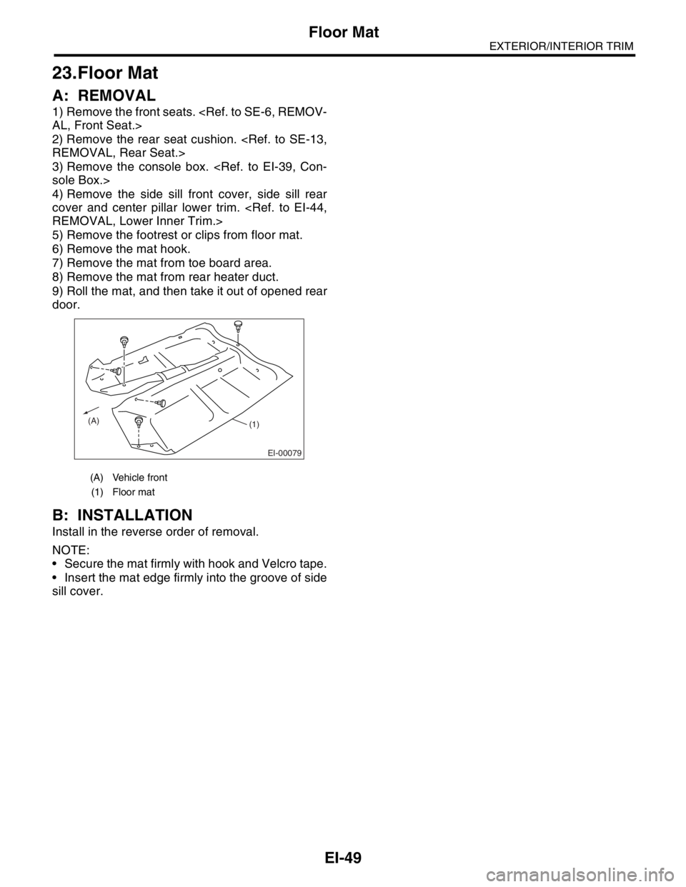
A: REMOVAL
1) Remove the front seats.
2) Remove the rear seat cushion.
3) Remove the console box.
4) Remove the side sill front cover, side sill rear
cover and center pillar lower trim.
5) Remove the footrest or clips from floor mat.
6) Remove the mat hook.
7) Remove the mat from toe board area.
8) Remove the mat from rear heater duct.
9) Roll the mat, and then take it out of opened rear
door.
B: INSTALLATION
Install in the reverse order of removal.
NOTE:
Secure the mat firmly with hook and Velcro tape.
Insert the mat edge firmly into the groove of side
sill cover.
(A) Vehicle front
(1) Floor mat
EI-00079
(A)(1)
Page 884 of 2870
ME(H4SO)-15
MECHANICAL
General Description
C: CAUTION
Wear working clothing, including a cap, protec-
tive goggles and protective shoes during operation.
Remove contamination including dirt and corro-
sion before removal, installation or disassembly.
Keep the disassembled parts in order and pro-
tect them from dust or dirt.
Before removal, installation or disassembly, be
sure to clarify the failure. Avoid unnecessary re-
moval, installation, disassembly and replacement.
Be careful not to burn yourself, because each
part in the vehicle is hot after running.
Be sure to tighten bolts and nuts to the specified
torque.
Place shop jacks or rigid racks at the specified
points.
Before disconnecting electrical connectors of
sensors or units, be sure to disconnect the ground
cable from battery.
All parts should be thoroughly cleaned, paying
special attention to the engine oil passages, pis-
tons and bearings. Rotating parts and sliding parts such as piston,
bearing and gear should be coated with oil prior to
assembly.
Be careful not to let oil, grease or coolant contact
the timing belt, clutch disc and flywheel.
All removed parts, if to be reused, should be re-
installed in the original positions and directions.
Bolts, nuts and washers should be replaced with
new ones as required.
Even if necessary inspections have been made
in advance, proceed with assembly work while
making rechecks.
Remove or install engine in an area where chain
hoists, lifting devices, etc. are available for ready
use.
Be sure not to damage coated surfaces of body
panels with tools, or not to stain seats and windows
with coolant or oil. Place a cover over fenders, as
required, for protection.
Prior to starting work, prepare the following:
Service tools, clean cloth, containers to catch cool-
ant and oil, wire ropes, chain hoist, transmission
jacks, etc.
Lift-up or lower the vehicle when necessary.
Make sure to support the correct positions.
D: PREPARATION TOOL
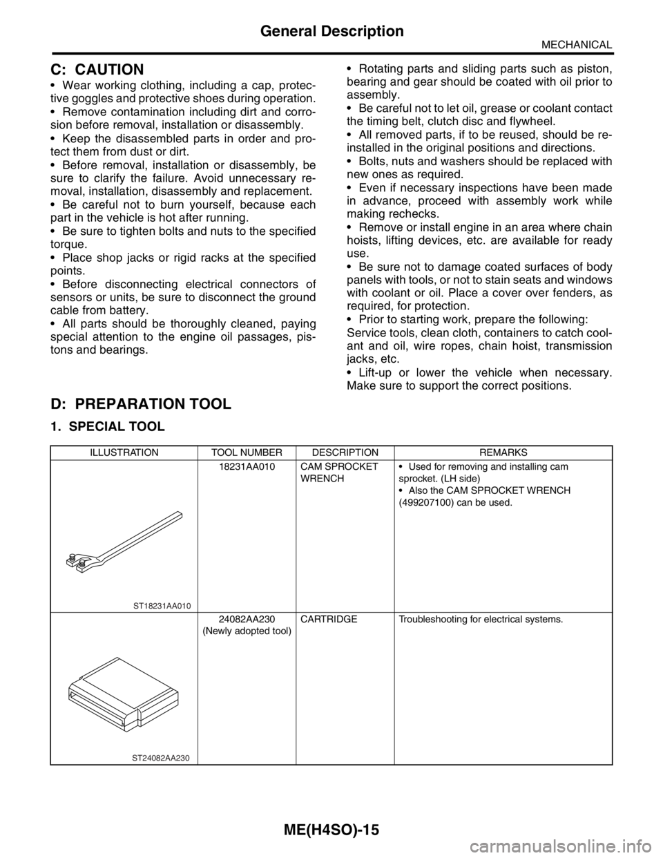
1. SPECIAL TOOL
ILLUSTRATION TOOL NUMBER DESCRIPTION REMARKS
18231AA010 CAM SPROCKET
WRENCH Used for removing and installing cam
sprocket. (LH side)
Also the CAM SPROCKET WRENCH
(499207100) can be used.
24082AA230
(Newly adopted tool)CARTRIDGE Troubleshooting for electrical systems.
ST18231AA010
ST24082AA230
Page 937 of 2870
ME(H4SO)-66
MECHANICAL
Cylinder Head
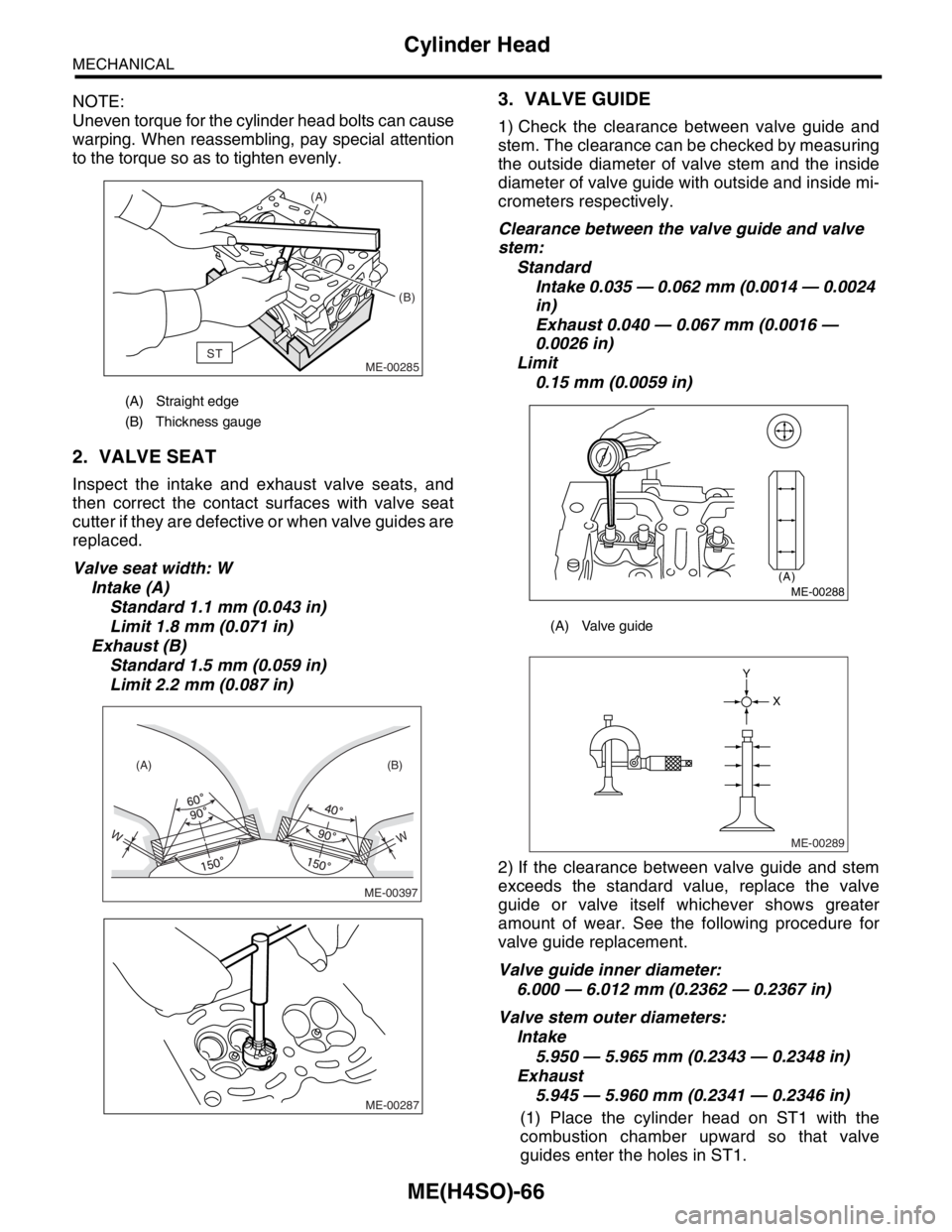
NOTE:
Uneven torque for the cylinder head bolts can cause
warping. When reassembling, pay special attention
to the torque so as to tighten evenly.
2. VALVE SEAT
Inspect the intake and exhaust valve seats, and
then correct the contact surfaces with valve seat
cutter if they are defective or when valve guides are
replaced.
Valve seat width: W
Intake (A)
Standard 1.1 mm (0.043 in)
Limit 1.8 mm (0.071 in)
Exhaust (B)
Standard 1.5 mm (0.059 in)
Limit 2.2 mm (0.087 in)
3. VALVE GUIDE
1) Check the clearance between valve guide and
stem. The clearance can be checked by measuring
the outside diameter of valve stem and the inside
diameter of valve guide with outside and inside mi-
crometers respectively.
Clearance between the valve guide and valve
stem:
Standard
Intake 0.035 — 0.062 mm (0.0014 — 0.0024
in)
Exhaust 0.040 — 0.067 mm (0.0016 —
0.0026 in)
Limit
0.15 mm (0.0059 in)
2) If the clearance between valve guide and stem
exceeds the standard value, replace the valve
guide or valve itself whichever shows greater
amount of wear. See the following procedure for
valve guide replacement.
Valve guide inner diameter:
6.000 — 6.012 mm (0.2362 — 0.2367 in)
Valve stem outer diameters:
Intake
5.950 — 5.965 mm (0.2343 — 0.2348 in)
Exhaust
5.945 — 5.960 mm (0.2341 — 0.2346 in)
(1) Place the cylinder head on ST1 with the
combustion chamber upward so that valve
guides enter the holes in ST1.
(A) Straight edge
(B) Thickness gauge
ST(A)
(B)
ME-00285
WW
(A) (B)
ME-00397
ME-00287
(A) Valve guide
(A)
ME-00288
ME-00289
X Y