Page 18 of 2870
AC-16
HVAC SYSTEM (HEATER, VENTILATOR AND A/C)
General Description
4. AIR CONDITIONING UNIT
LHD MODEL
(1) Condenser (5) CompressorTightening torque: N·m (kgf-m, ft-lb)
(2) High-pressure hose (6) O-ringT1: 7.4 (0.75, 5.4)
(3) Low-pressure hose (7) Triple pressure switchT2: 15 (1.5, 10.8)
(4) Pipe
AC-00866
(1)(3)
(4)
(7) (5)
(2)
T1
T1T2(6) (6)
(6)(6)
(6) T2(6)
Page 38 of 2870
AC-36
HVAC SYSTEM (HEATER, VENTILATOR AND A/C)
Compressor
11.Compressor
A: INSPECTION
1. MAGNETIC CLUTCH CLEARANCE
1) Check the clearance of the entire circumference
around the drive plate and pulley.
Standard:
0.3 — 0.6 mm (0.0118 — 0.0236 in)
2. MAGNETIC CLUTCH OPERATION
1) Disconnect the compressor connector.
2) Connect the battery positive (+) terminal to the
No. 3 terminal of the compressor connector.
3) Make sure the magnet clutch engages.
If NG, replace the compressor.
B: REMOVAL
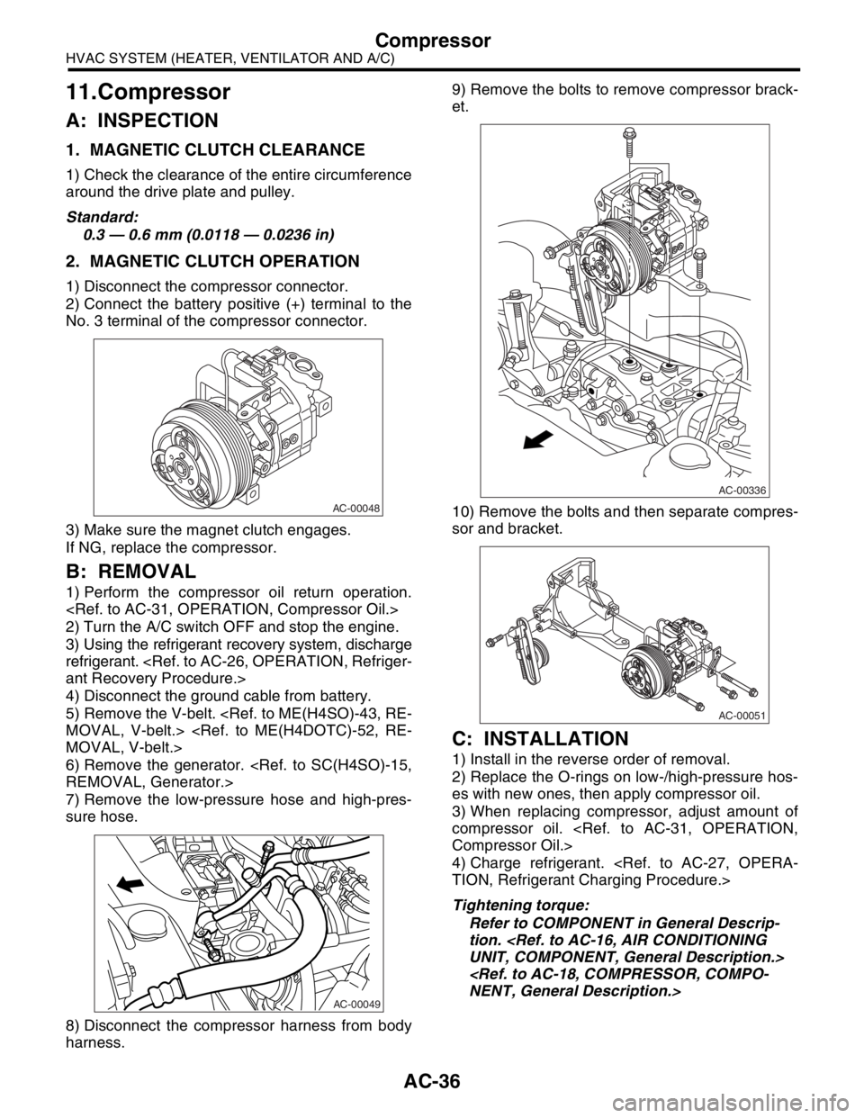
1) Perform the compressor oil return operation.
2) Turn the A/C switch OFF and stop the engine.
3) Using the refrigerant recovery system, discharge
refrigerant.
ant Recovery Procedure.>
4) Disconnect the ground cable from battery.
5) Remove the V-belt.
MOVAL, V-belt.>
MOVAL, V-belt.>
6) Remove the generator.
REMOVAL, Generator.>
7) Remove the low-pressure hose and high-pres-
sure hose.
8) Disconnect the compressor harness from body
harness.9) Remove the bolts to remove compressor brack-
et.
10) Remove the bolts and then separate compres-
sor and bracket.
C: INSTALLATION
1) Install in the reverse order of removal.
2) Replace the O-rings on low-/high-pressure hos-
es with new ones, then apply compressor oil.
3) When replacing compressor, adjust amount of
compressor oil.
Compressor Oil.>
4) Charge refrigerant.
TION, Refrigerant Charging Procedure.>
Tightening torque:
Refer to COMPONENT in General Descrip-
tion.
UNIT, COMPONENT, General Description.>
NENT, General Description.>
AC-00048
AC-00049
AC-00336
AC-00051
Page 39 of 2870
AC-37
HVAC SYSTEM (HEATER, VENTILATOR AND A/C)
Condenser
12.Condenser
A: REMOVAL
1) Using the refrigerant recovery system, discharge
refrigerant.
ant Recovery Procedure.>
2) Disconnect the ground cable from battery.
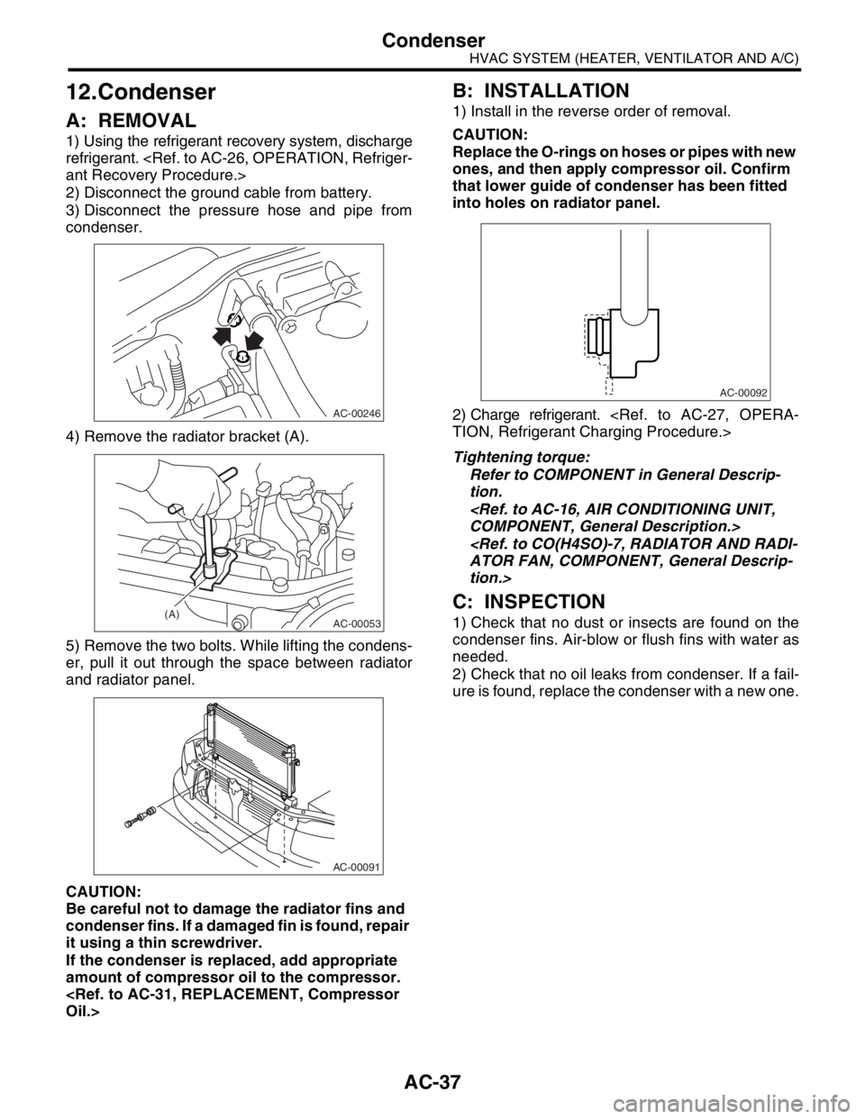
3) Disconnect the pressure hose and pipe from
condenser.
4) Remove the radiator bracket (A).
5) Remove the two bolts. While lifting the condens-
er, pull it out through the space between radiator
and radiator panel.
CAUTION:
Be careful not to damage the radiator fins and
condenser fins. If a damaged fin is found, repair
it using a thin screwdriver.
If the condenser is replaced, add appropriate
amount of compressor oil to the compressor.
Oil.>
B: INSTALLATION
1) Install in the reverse order of removal.
CAUTION:
Replace the O-rings on hoses or pipes with new
ones, and then apply compressor oil. Confirm
that lower guide of condenser has been fitted
into holes on radiator panel.
2) Charge refrigerant.
TION, Refrigerant Charging Procedure.>
Tightening torque:
Refer to COMPONENT in General Descrip-
tion.
COMPONENT, General Description.>
ATOR FAN, COMPONENT, General Descrip-
tion.>
C: INSPECTION
1) Check that no dust or insects are found on the
condenser fins. Air-blow or flush fins with water as
needed.
2) Check that no oil leaks from condenser. If a fail-
ure is found, replace the condenser with a new one.
AC-00246
AC-00053(A)
AC-00091
AC-00092
Page 43 of 2870
AC-41
HVAC SYSTEM (HEATER, VENTILATOR AND A/C)
Hose and Tube
16.Hose and Tube
A: REMOVAL
CAUTION:
When disconnecting/connecting hoses, do not
apply excessive force to them. Confirm that no
torsion and excessive tension exists after install-
ing.
Seal the disconnected hose with a plug or vi-
nyl tape to prevent foreign matters from enter-
ing.
1) Disconnect the ground cable from battery.
2) Using the refrigerant recovery system, dis-
charge refrigerant.
Refrigerant Recovery Procedure.>
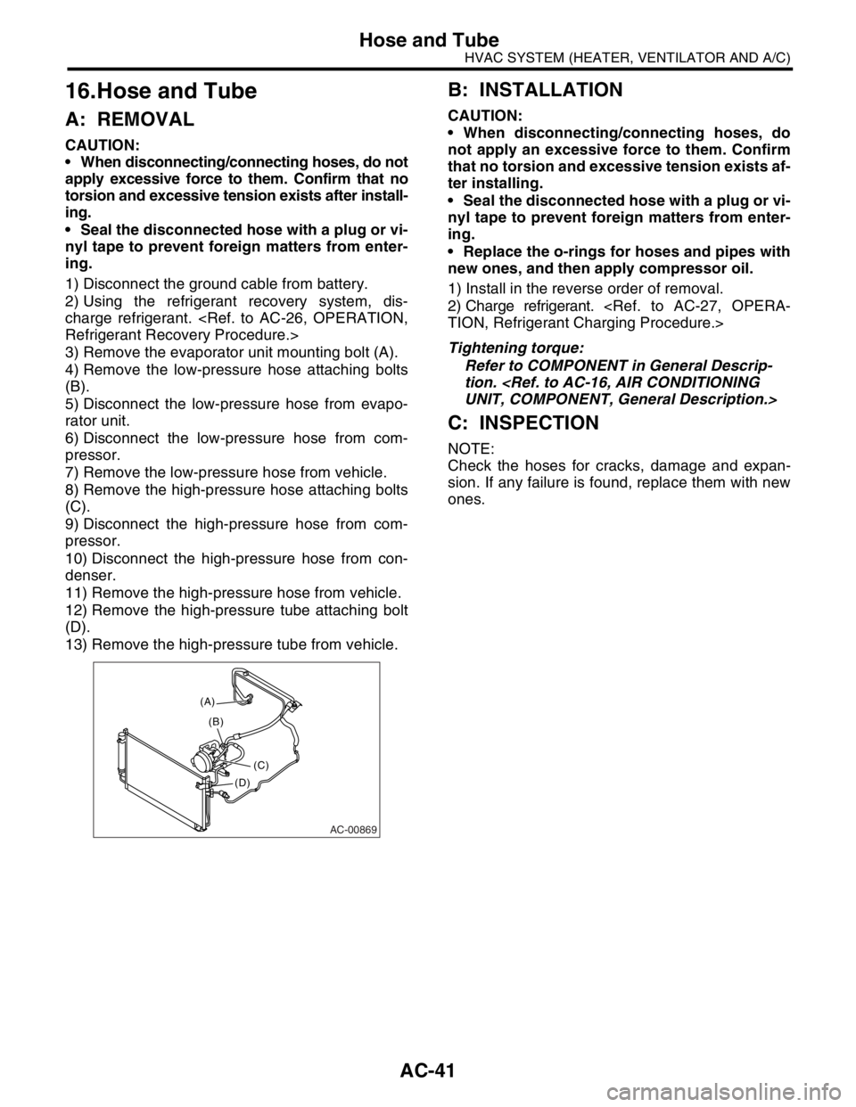
3) Remove the evaporator unit mounting bolt (A).
4) Remove the low-pressure hose attaching bolts
(B).
5) Disconnect the low-pressure hose from evapo-
rator unit.
6) Disconnect the low-pressure hose from com-
pressor.
7) Remove the low-pressure hose from vehicle.
8) Remove the high-pressure hose attaching bolts
(C).
9) Disconnect the high-pressure hose from com-
pressor.
10) Disconnect the high-pressure hose from con-
denser.
11) Remove the high-pressure hose from vehicle.
12) Remove the high-pressure tube attaching bolt
(D).
13) Remove the high-pressure tube from vehicle.
B: INSTALLATION
CAUTION:
When disconnecting/connecting hoses, do
not apply an excessive force to them. Confirm
that no torsion and excessive tension exists af-
ter installing.
Seal the disconnected hose with a plug or vi-
nyl tape to prevent foreign matters from enter-
ing.
Replace the o-rings for hoses and pipes with
new ones, and then apply compressor oil.
1) Install in the reverse order of removal.
2) Charge refrigerant.
TION, Refrigerant Charging Procedure.>
Tightening torque:
Refer to COMPONENT in General Descrip-
tion.
UNIT, COMPONENT, General Description.>
C: INSPECTION
NOTE:
Check the hoses for cracks, damage and expan-
sion. If any failure is found, replace them with new
ones.
AC-00869
(A)
(C) (B)
(D)
Page 64 of 2870
AC-8
HVAC SYSTEM (AUTO A/C)(DIAGNOSTIC)
Auto A/C Control Module I/O Signal
*1: Battery voltage is indicated when motor running, 0 V or battery voltage pulse signal is output when motor stops.
*2: Battery voltage is indicated when motor running, 0 V is indicated when motor stops.
*3: Voltage can not be measured because of pulse signal.
B: WIRING DIAGRAM:
A14Combination meter (ambient temperature sig-
nal)*3 *3
A13 Mode door actuator position detection signal OutletVENT, BI-LEVEL, HEAT 5 V
DEF/HEAT, DEF 0 V
A12 Mode door actuator position detection signal OutletVENT, DEF/HEAT 5 V
BI-LEVEL, HEAT, DEF 0 V
A10 A/C cutout signalA/C: ON Battery voltage
Pressure switch operated 0 V
A9 Illumination ground When there is continuity to chassis ground 0 Ω Terminal No. Content Measuring conditionSpecified
value
Page 748 of 2870
PM-11
PERIODIC MAINTENANCE SERVICE
V-belt
6. V-belt
A: INSPECTION
1) Replace the belts, if cracks, fraying or wear is
found.
2) Check the V-belt tension and adjust it if neces-
sary by changing the generator installing position
or idler pulley installing position.
REPLACEMENT, V-belt.>
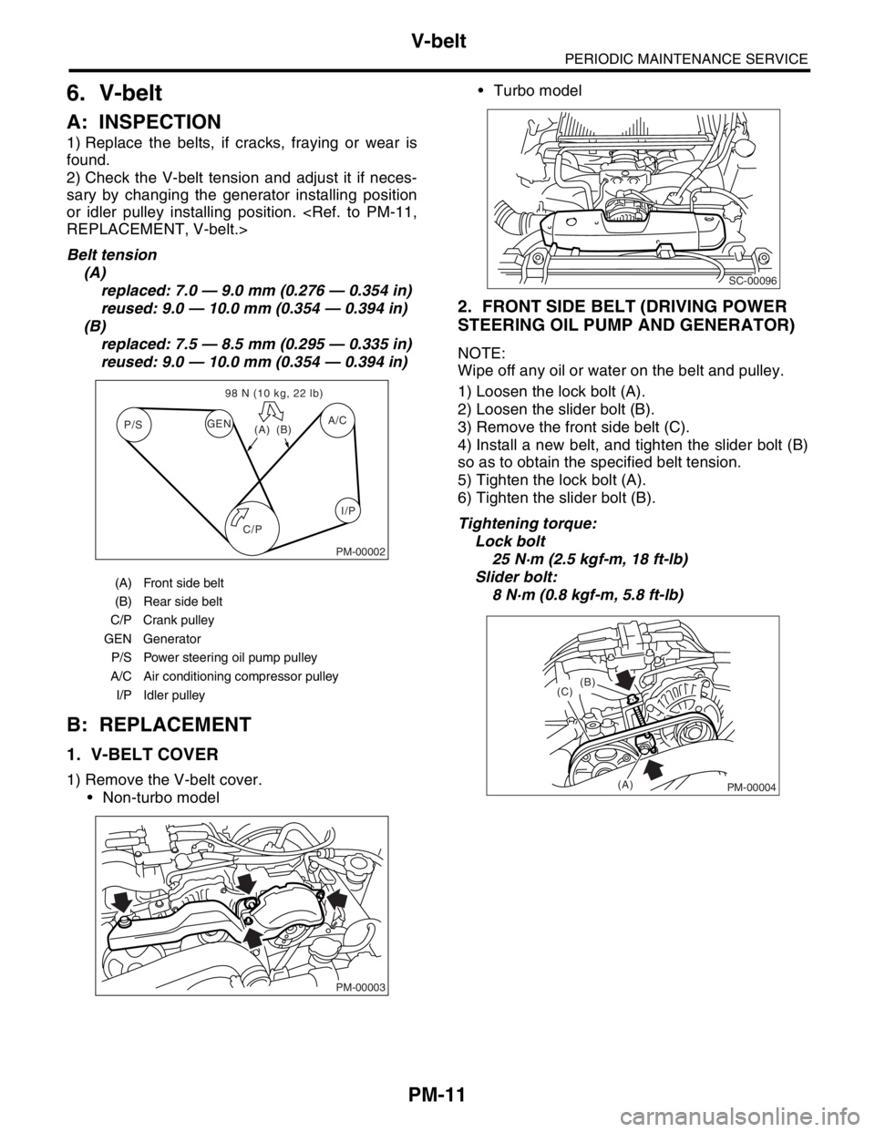
Belt tension
(A)
replaced: 7.0 — 9.0 mm (0.276 — 0.354 in)
reused: 9.0 — 10.0 mm (0.354 — 0.394 in)
(B)
replaced: 7.5 — 8.5 mm (0.295 — 0.335 in)
reused: 9.0 — 10.0 mm (0.354 — 0.394 in)
B: REPLACEMENT
1. V-BELT COVER
1) Remove the V-belt cover.
Non-turbo model Turbo model
2. FRONT SIDE BELT (DRIVING POWER
STEERING OIL PUMP AND GENERATOR)
NOTE:
Wipe off any oil or water on the belt and pulley.
1) Loosen the lock bolt (A).
2) Loosen the slider bolt (B).
3) Remove the front side belt (C).
4) Install a new belt, and tighten the slider bolt (B)
so as to obtain the specified belt tension.
5) Tighten the lock bolt (A).
6) Tighten the slider bolt (B).
Tightening torque:
Lock bolt
25 N·m (2.5 kgf-m, 18 ft-lb)
Slider bolt:
8 N·m (0.8 kgf-m, 5.8 ft-lb)
(A) Front side belt
(B) Rear side belt
C/P Crank pulley
GEN Generator
P/S Power steering oil pump pulley
A/C Air conditioning compressor pulley
I/P Idler pulley
C/P P/SA/C
GEN
(A)(B) 98 N (10 kg, 22 lb)
I/P
PM-00002
PM-00003
SC-00096
PM-00004
(B)
(C)
(A)
Page 750 of 2870
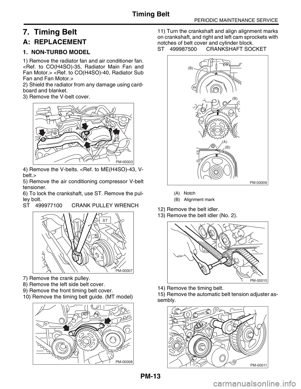
PM-13
PERIODIC MAINTENANCE SERVICE
Timing Belt
7. Timing Belt
A: REPLACEMENT
1. NON-TURBO MODEL
1) Remove the radiator fan and air conditioner fan.
Fan Motor.>
Fan and Fan Motor.>
2) Shield the radiator from any damage using card-
board and blanket.
3) Remove the V-belt cover.
4) Remove the V-belts.
belt.>
5) Remove the air conditioning compressor V-belt
tensioner.
6) To lock the crankshaft, use ST. Remove the pul-
ley bolt.
ST 499977100 CRANK PULLEY WRENCH
7) Remove the crank pulley.
8) Remove the left side belt cover.
9) Remove the front timing belt cover.
10) Remove the timing belt guide. (MT model)11) Turn the crankshaft and align alignment marks
on crankshaft, and right and left cam sprockets with
notches of belt cover and cylinder block.
ST 499987500 CRANKSHAFT SOCKET
12) Remove the belt idler.
13) Remove the belt idler (No. 2).
14) Remove the timing belt.
15) Remove the automatic belt tension adjuster as-
sembly.
PM-00003
PM-00007
ST
PM-00008
(A) Notch
(B) Alignment mark
PM-00009
(B)
(B)
(B) (A)
PM-00010
PM-00011
Page 751 of 2870
PM-14
PERIODIC MAINTENANCE SERVICE
Timing Belt
16) Install in the reverse order of removal.
ME(H4SO)-49, INSTALLATION, Timing Belt.>
2. TURBO MODEL
1) Remove the radiator fan and air conditioner fan.
Fan Motor.>
Fan and Fan Motor.>
2) Protect the radiator with cardboard and blanket.
3) Remove the V-belts.
belt.>
4) Remove the air conditioning compressor drive
belt tensioner.
5) To lock the crankshaft use ST. Remove the pul-
ley bolt.
ST 499977300 CRANK PULLEY WRENCH
6) Remove the crank pulley.
7) Remove the air conditioning compressor drive
belt tensioner.
8) Remove the belt cover (LH).
9) Remove the belt cover (RH).
10) Remove the front belt cover.11) Remove the timing belt guide. (MT model)
12) Turn the crankshaft and align alignment marks
on crankshaft, and right and left cam sprockets with
notches of belt cover and cylinder block. To turn the
crankshaft, use ST.
STPM-00093
PM-00008
ME-00727
ME-00728
ME-00729