2004 SUBARU FORESTER Head light
[x] Cancel search: Head lightPage 255 of 2870

LIGHTING SYSTEM
LI
Page
1. General Description ....................................................................................2
2. Headlight and Tail Light System .................................................................3
3. Front Fog Light System ...............................................................................4
4. Rear Fog Light System ...............................................................................5
5. Turn Signal Light and Hazard Light System................................................6
6. Back-up Light System .................................................................................7
7. Stop Light System .......................................................................................8
8. Room Light System .....................................................................................9
9. Headlight Beam Leveler System ...............................................................10
10. Combination Switch (Light) .......................................................................11
11. Headlight Assembly ..................................................................................13
12. Headlight Bulb ...........................................................................................16
13. Front Turn Signal Light Bulb .....................................................................17
14. Clearance Light Bulb .................................................................................18
15. Front Fog Light Assembly .........................................................................19
16. Front Fog Light Bulb..................................................................................20
17. Rear Combination Light Assembly ............................................................21
18. Tail/Stop Light Bulb ...................................................................................22
19. Back-up Light Bulb ....................................................................................23
20. Rear Turn Signal Light Bulb ......................................................................24
21. Rear Fog Light Bulb ..................................................................................25
22. License Plate Light ....................................................................................26
23. High-mounted Stop Light ..........................................................................27
24. Side Turn Signal Light ...............................................................................28
25. Spot Map Light ..........................................................................................29
26. Room Light ................................................................................................30
27. Luggage Room Light .................................................................................31
28. Glove Box Light .........................................................................................32
Page 256 of 2870

LI-2
LIGHTING SYSTEM
General Description
1. General Description
A: SPECIFICATION
B: PRECAUTIONS
Before removing and installing parts, always disconnect the battery ground cable. When replacing audio,
control module, and other parts provided with memory functions, record memory contents before disconnect-
ing the battery ground cable. Otherwise, the memory will be erased.
Reassemble in reverse order of disassembly, unless otherwise indicated.
Adjust parts to the given specifications.
Connect the connectors and hoses securely during reassembly.
After reassembly, make sure functional parts operate smoothly.
WARNING:
Airbag system wiring harness is routed near electrical parts and switches. All airbag system wiring
harnesses and connectors are yellow. Do not use electric test equipment on these circuits.
Be careful not to damage the airbag system wiring harness when servicing electrical parts and
switches.
C: PREPARATION TOOL
1. GENERAL TOOL
Headlight12 V — 55 W/60 W
Front turn signal light 12 V — 21 W
Clearance light12 V — 5 W
Side marker light12 V — 5 W
Front fog light12 V — 55 W
Rear combination lightTail/Stop light 12 V — 5/21 W
Turn signal light 12 V — 21 W
Back-up light 12 V — 16 W
License plate light12 V — 5 W
High-mounted stop lightStandard type 12 V — 13 W
Rear spoiler built-in type 12 V — 1.2 W
Room light12 V — 8 W
Spot light12 V — 8 W
Luggage room light12 V — 5 W
TOOL NAME REMARKS
Circuit tester Used for measuring resistance and voltage.
Page 257 of 2870
LI-3
LIGHTING SYSTEM
Headlight and Tail Light System
2. Headlight and Tail Light Sys-
tem
A: WIRING DIAGRAM
1. HEADLIGHT
2. CLEARANCE LIGHT AND ILLUMINA-
TION LIGHT
B: INSPECTION
1. HEADLIGHT SWITCH
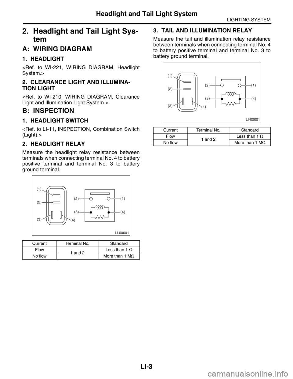
2. HEADLIGHT RELAY
Measure the headlight relay resistance between
terminals when connecting terminal No. 4 to battery
positive terminal and terminal No. 3 to battery
ground terminal.
3. TAIL AND ILLUMINATION RELAY
Measure the tail and illumination relay resistance
between terminals when connecting terminal No. 4
to battery positive terminal and terminal No. 3 to
battery ground terminal.
Current Terminal No. Standard
Flow
1 and 2Less than 1 Ω
No flow More than 1 MΩ
LI-00001
(1)
(2) (1)
(4)(2)
(3)
(3)(4)
Current Terminal No. Standard
Flow
1 and 2Less than 1 Ω
No flow More than 1 MΩ
LI-00001
(1)
(2) (1)
(4)(2)
(3)
(3)(4)
Page 259 of 2870
LI-5
LIGHTING SYSTEM
Rear Fog Light System
4. Rear Fog Light System
A: WIRING DIAGRAM
1. REAR FOG LIGHT
B: INSPECTION
1. REAR FOG LIGHT SWITCH
1) Turn the ignition switch to ON.
2) Turn on the headlight or front fog light.
3) Push the rear fog light switch and check if the
rear fog light turns on.
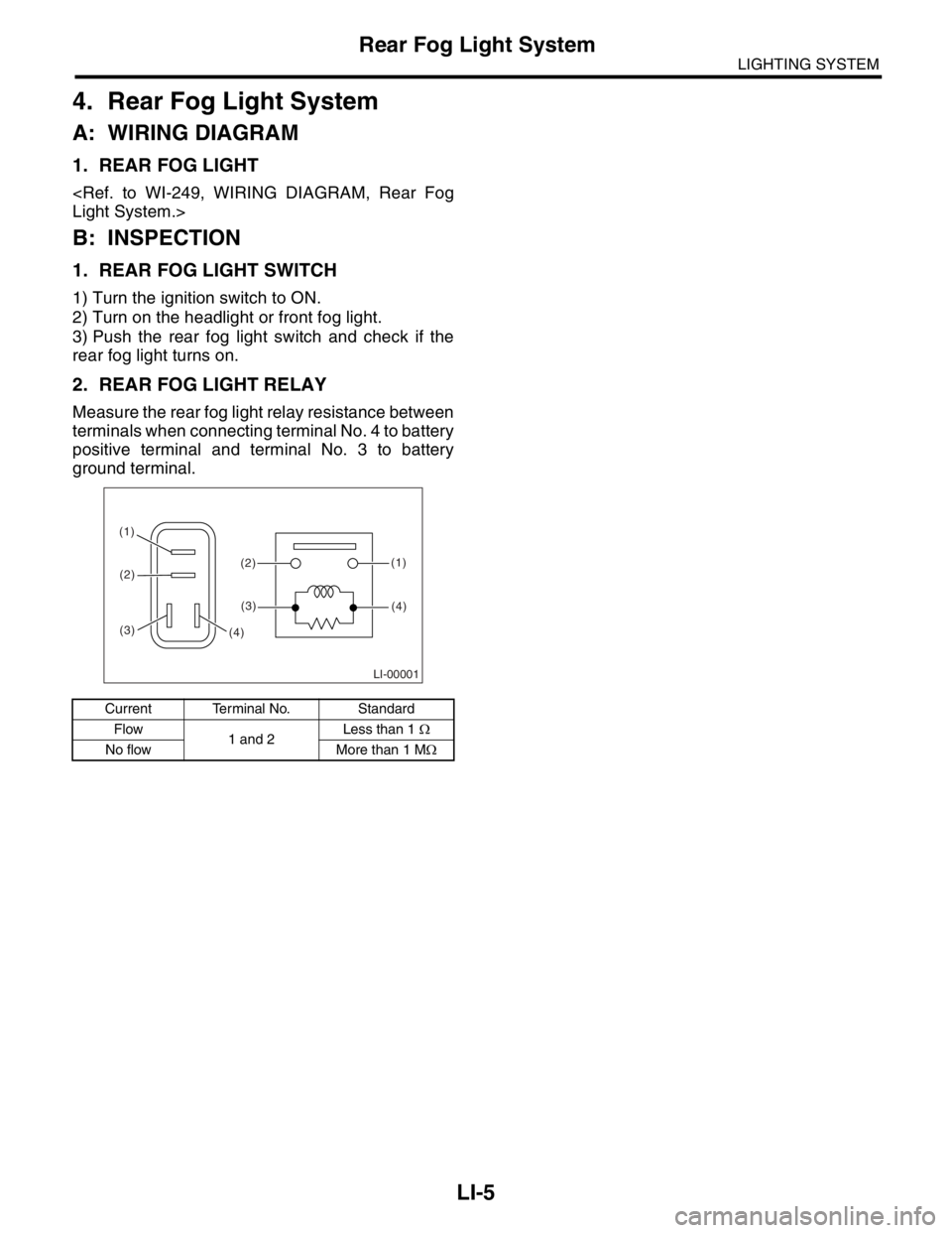
2. REAR FOG LIGHT RELAY
Measure the rear fog light relay resistance between
terminals when connecting terminal No. 4 to battery
positive terminal and terminal No. 3 to battery
ground terminal.
Current Terminal No. Standard
Flow
1 and 2Less than 1 Ω
No flow More than 1 MΩ
LI-00001
(1)
(2) (1)
(4)(2)
(3)
(3)(4)
Page 264 of 2870
LI-10
LIGHTING SYSTEM
Headlight Beam Leveler System
9. Headlight Beam Leveler Sys-
tem
A: WIRING DIAGRAM
1. HEADLIGHT BEAM LEVELER
B: INSPECTION
1. HEADLIGHT BEAM LEVELER ACTUA-
TOR
1) Turn on the headlights.
2) Confirm the headlight beam level is lowered by
changing the switch position to 0 → 1 → 2 → 3 →
4 → 5.
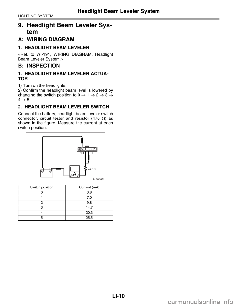
2. HEADLIGHT BEAM LEVELER SWITCH
Connect the battery, headlight beam leveler switch
connector, circuit tester and resistor (470 Ω) as
shown in the figure. Measure the current at each
switch position.
Switch position Current (mA)
03.8
17.0
29.8
3 14.7
4 20.3
5 25.5
65 4 2 1
LI-00008A
RH LH
470 3
Page 265 of 2870
LI-11
LIGHTING SYSTEM
Combination Switch (Light)
10.Combination Switch (Light)
A: REMOVAL
1) Disconnect the ground cable from battery.
2) Remove the instrument panel lower cover.
3) Remove the screw which secure upper column
cover to lower column cover.
4) Disconnect the connector from combination switch.
5) Remove the screws which secure switch, and
then remove the switch.
B: INSTALLATION
Install in the reverse order of removal.
C: INSPECTION
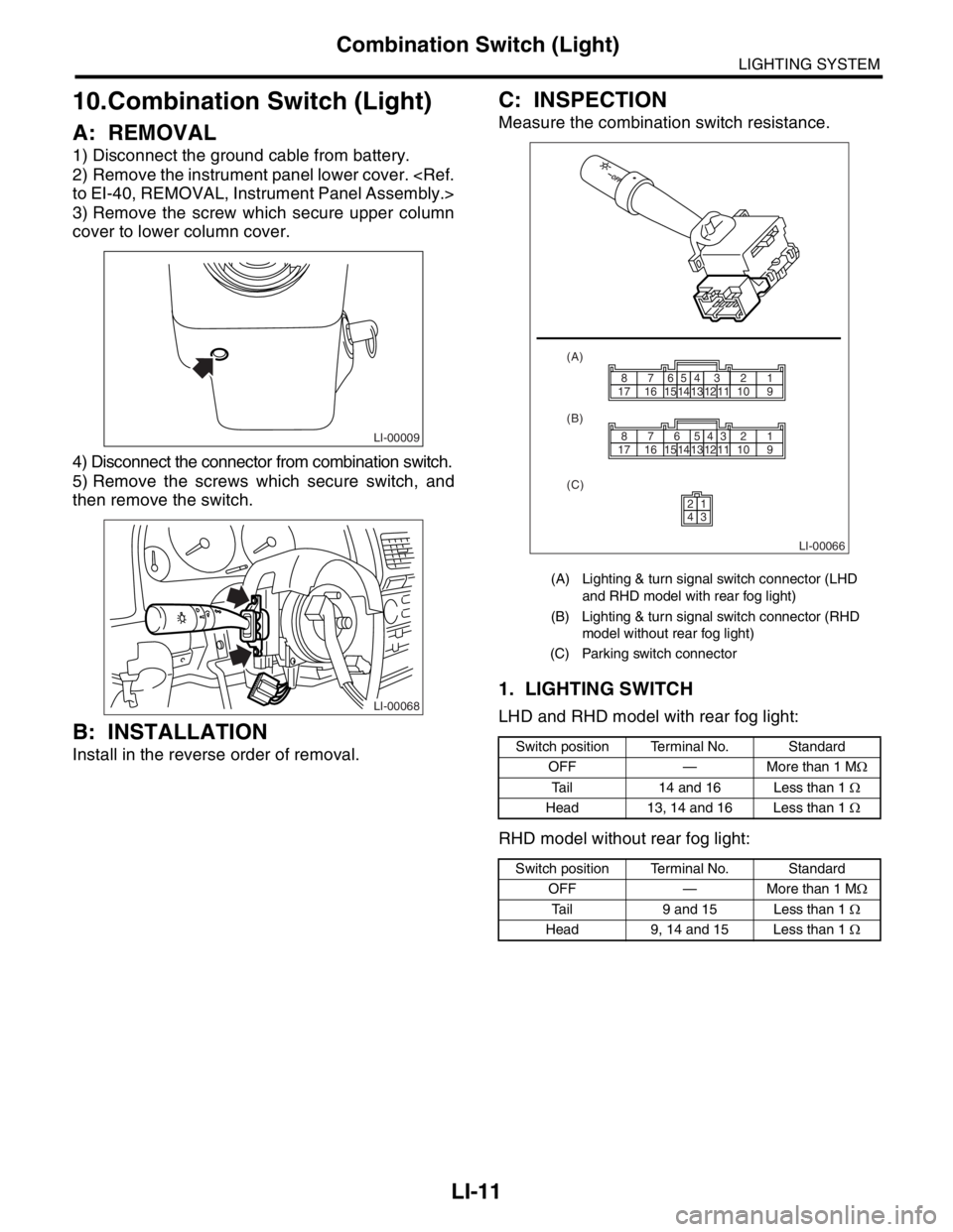
Measure the combination switch resistance.
1. LIGHTING SWITCH
LHD and RHD model with rear fog light:
RHD model without rear fog light:
LI-00009
LI-00068
(A) Lighting & turn signal switch connector (LHD
and RHD model with rear fog light)
(B) Lighting & turn signal switch connector (RHD
model without rear fog light)
(C) Parking switch connector
Switch position Terminal No. Standard
OFF — More than 1 MΩ
Tail 14 and 16 Less than 1 Ω
Head 13, 14 and 16 Less than 1 Ω
Switch position Terminal No. Standard
OFF — More than 1 MΩ
Tail 9 and 15 Less than 1 Ω
Head 9, 14 and 15 Less than 1 Ω
LI-00066
1514131211109171665432187
1514
2143
131211109171665432187
(A)
(B)
(C)
Page 267 of 2870
LI-13
LIGHTING SYSTEM
Headlight Assembly
11.Headlight Assembly
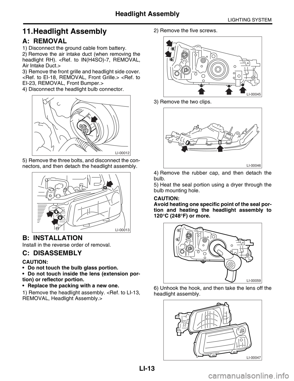
A: REMOVAL
1) Disconnect the ground cable from battery.
2) Remove the air intake duct (when removing the
headlight RH).
3) Remove the front grille and headlight side cover.
4) Disconnect the headlight bulb connector.
5) Remove the three bolts, and disconnect the con-
nectors, and then detach the headlight assembly.
B: INSTALLATION
Install in the reverse order of removal.
C: DISASSEMBLY
CAUTION:
Do not touch the bulb glass portion.
Do not touch inside the lens (extension por-
tion) or reflector portion.
Replace the packing with a new one.
1) Remove the headlight assembly.
3) Remove the two clips.
4) Remove the rubber cap, and then detach the
bulb.
5) Heat the seal portion using a dryer through the
bulb mounting hole.
CAUTION:
Avoid heating one specific point of the seal por-
tion and heating the headlight assembly to
120°C (248°F) or more.
6) Unhook the hook, and then take the lens off the
headlight assembly.
LI-00012
LI-00013
LI-00045
LI-00046
LI-00059
LI-00047
Page 268 of 2870
LI-14
LIGHTING SYSTEM
Headlight Assembly
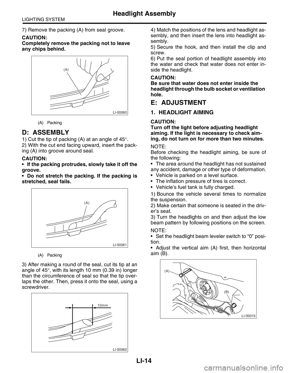
7) Remove the packing (A) from seal groove.
CAUTION:
Completely remove the packing not to leave
any chips behind.
D: ASSEMBLY
1) Cut the tip of packing (A) at an angle of 45°.
2) With the cut end facing upward, insert the pack-
ing (A) into groove around seal.
CAUTION:
If the packing protrudes, slowly take it off the
groove.
Do not stretch the packing. If the packing is
stretched, seal fails.
3) After making a round of the seal, cut its tip at an
angle of 45°, with its length 10 mm (0.39 in) longer
than the circumference of seal so that the tip over-
laps the other. Then, press it onto the seal, using a
screwdriver.4) Match the positions of the lens and headlight as-
sembly, and then insert the lens into headlight as-
sembly.
5) Secure the hook, and then install the clip and
screw.
6) Put the seal portion of headlight assembly into
the water and check that water does not enter in-
side the headlight.
CAUTION:
Be sure that water does not enter inside the
headlight through the bulb socket or ventilation
hole.
E: ADJUSTMENT
1. HEADLIGHT AIMING
CAUTION:
Turn off the light before adjusting headlight
aiming. If the light is necessary to check aim-
ing, do not turn on for more than two minutes.
NOTE:
Before checking the headlight aiming, be sure of
the following:
The area around the headlight has not sustained
any accident, damage or other type of deformation.
Vehicle is parked on a level surface.
The inflation pressure of tires is correct.
Vehicle’s fuel tank is fully charged.
1) Bounce the vehicle several times to normalize
the suspension.
2) Make certain that someone is seated in the driv-
er’s seat.
3) Turn the headlights on and then adjust the low
beam pattern by following positions on the screen.
NOTE:
Set the headlight beam leveler switch to “0” posi-
tion.
Adjust the vertical aim (A) first, then horizontal
aim (B).(A) Packing
(A) Packing
LI-00060
(A)
LI-00061
(A)
LI-00062
10mm
LI-00015
(A)
(B)