2004 SUBARU FORESTER door lock
[x] Cancel search: door lockPage 421 of 2870

SECURITY AND LOCK
SL
Page
1. General Description ....................................................................................2
2. Door Lock Control System ..........................................................................9
3. Keyless Entry System ...............................................................................14
4. Front Inner Remote ...................................................................................22
5. Front Outer Handle ...................................................................................23
6. Front Door Latch Assembly.......................................................................24
7. Front Door Lock Actuator ..........................................................................25
8. Rear Inner Remote....................................................................................26
9. Rear Outer Handle ....................................................................................27
10. Rear Door Latch Assembly .......................................................................28
11. Rear Door Lock Actuator...........................................................................29
12. Rear Gate Outer Handle ...........................................................................30
13. Rear Gate Latch Assembly .......................................................................31
14. Rear Gate Latch Lock Actuator .................................................................32
15. Front Hood Lock Assembly .......................................................................33
16. Remote Openers .......................................................................................34
17. Ignition Key Lock .......................................................................................35
18. Key Lock Cylinder .....................................................................................36
19. Immobilizer Control Module ......................................................................37
20. Immobilizer Antenna .................................................................................38
21. Keyless Entry Control Module ...................................................................39
22. Double Lock Module .................................................................................40
23. Keyless Transmitter ..................................................................................41
Page 422 of 2870

SL-2
SECURITY AND LOCK
General Description
1. General Description
A: COMPONENT
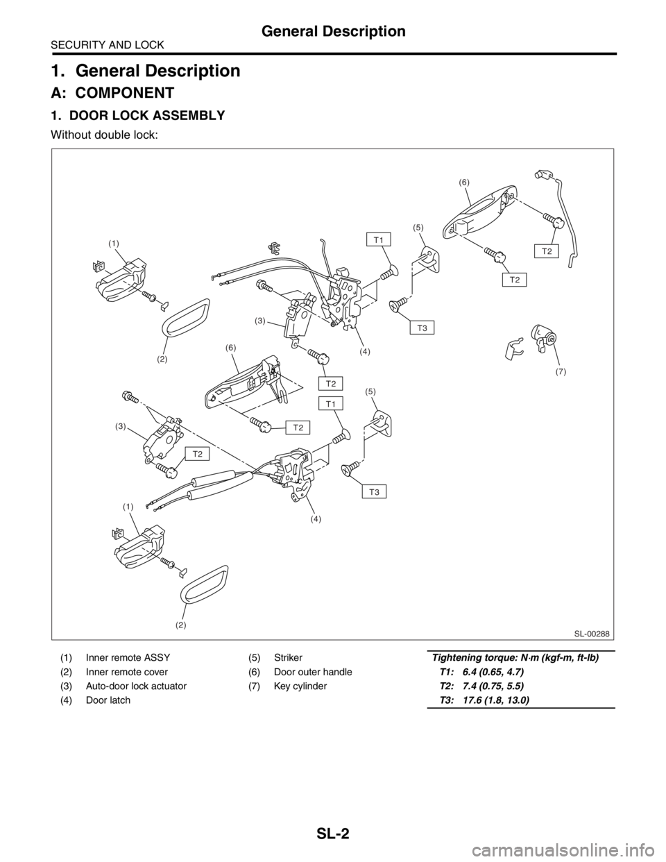
1. DOOR LOCK ASSEMBLY
Without double lock:
(1) Inner remote ASSY (5) Striker Tightening torque: N⋅m (kgf-m, ft-lb)
(2) Inner remote cover (6) Door outer handleT1: 6.4 (0.65, 4.7)
(3) Auto-door lock actuator (7) Key cylinderT2: 7.4 (0.75, 5.5)
(4) Door latch T3: 17.6 (1.8, 13.0)
SL-00288
T1
T1
T3
T3
T2
T2 (1)
(2)
(3)
(1)
(2)(3)
(4)(4)
(5)(5)
(6)(6)
(7)
T2
T2
T2
Page 423 of 2870

SL-3
SECURITY AND LOCK
General Description
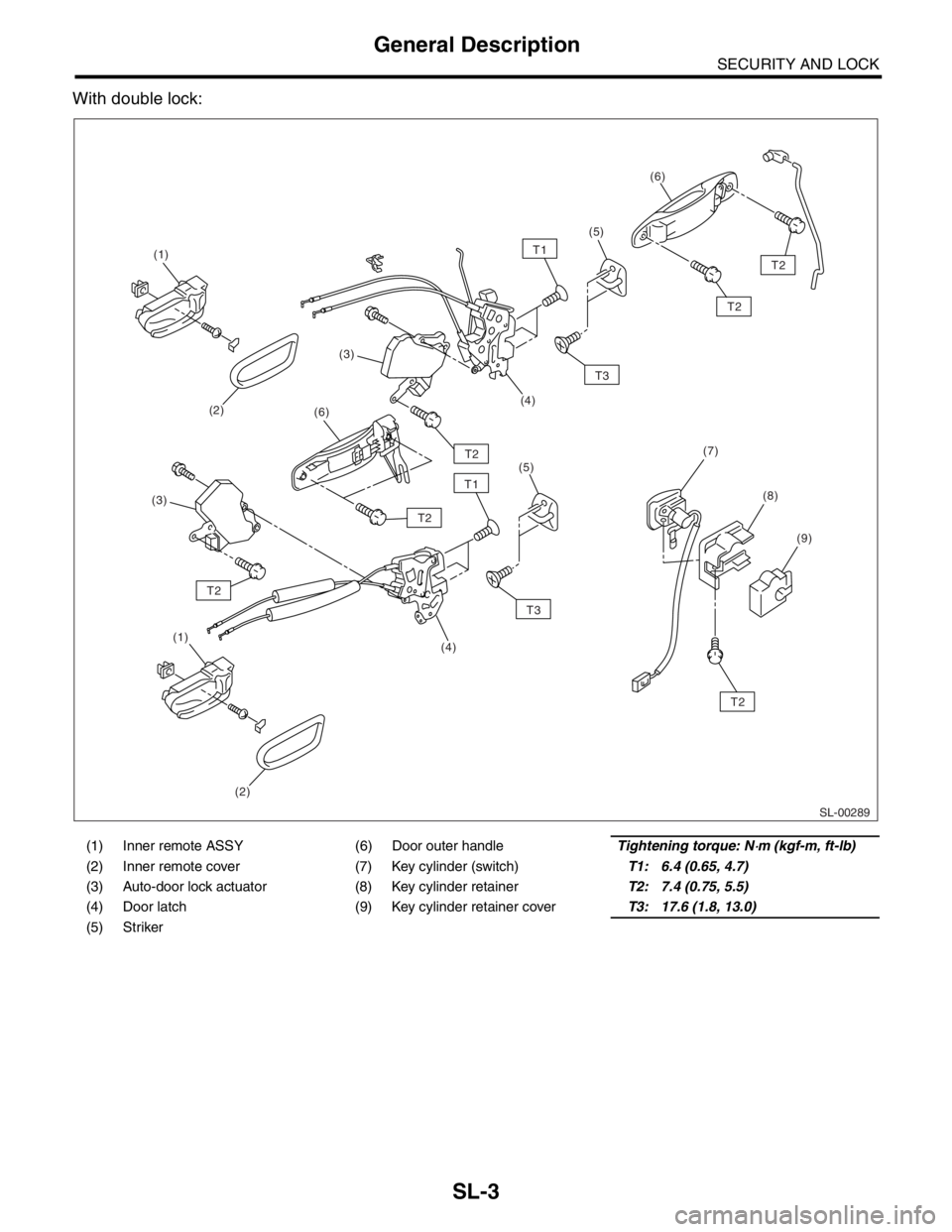
With double lock:
(1) Inner remote ASSY (6) Door outer handleTightening torque: N⋅m (kgf-m, ft-lb)
(2) Inner remote cover (7) Key cylinder (switch)T1: 6.4 (0.65, 4.7)
(3) Auto-door lock actuator (8) Key cylinder retainerT2: 7.4 (0.75, 5.5)
(4) Door latch (9) Key cylinder retainer coverT3: 17.6 (1.8, 13.0)
(5) Striker
SL-00289
T1
T1
T3
T3
T2
T2 (1)
(2)
(1)
(2)(3)
(4)(4)
(5)(5)
(3)
(6)(6)
(7)
(8)
(9)
T2
T2
T2
T2
Page 427 of 2870

SL-7
SECURITY AND LOCK
General Description
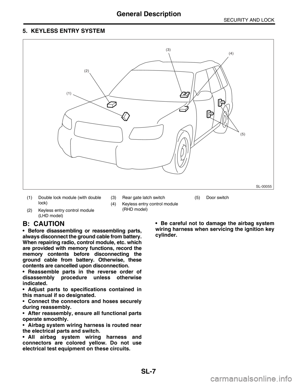
5. KEYLESS ENTRY SYSTEM
B: CAUTION
Before disassembling or reassembling parts,
always disconnect the ground cable from battery.
When repairing radio, control module, etc. which
are provided with memory functions, record the
memory contents before disconnecting the
ground cable from battery. Otherwise, these
contents are cancelled upon disconnection.
Reassemble parts in the reverse order of
disassembly procedure unless otherwise
indicated.
Adjust parts to specifications contained in
this manual if so designated.
Connect the connectors and hoses securely
during reassembly.
After reassembly, ensure all functional parts
operate smoothly.
Airbag system wiring harness is routed near
the electrical parts and switch.
All airbag system wiring harness and
connectors are colored yellow. Do not use
electrical test equipment on these circuits. Be careful not to damage the airbag system
wiring harness when servicing the ignition key
cylinder.
(1) Double lock module (with double
lock)(3) Rear gate latch switch (5) Door switch
(4) Keyless entry control module
(RHD model)
(2) Keyless entry control module
(LHD model)
SL-00055
(2)
(5)
(4)(3)
(1)
Page 429 of 2870

SL-9
SECURITY AND LOCK
Door Lock Control System
2. Door Lock Control System
A: WIRING DIAGRAM
1. DOOR LOCK CONTROL
B: INSPECTION
1. SYMPTOM CHART
Symptom Repair order Reference
The door lock control system does
not operate.1. Check the fuse.
System.>
2. Check the power supply and ground circuit for
keyless entry control module (without double lock)
or double lock module (with double lock).
INSPECTION, Door Lock Control
System.>
3. Check the door lock switch and the circuit.
INSPECTION, Door Lock Control
System.>
4. Check the door lock actuator and the circuit.
INSPECTION, Door Lock Control
System.>
The door lock switch does not oper-
ate.Check the door lock switch and the circuit.
INSPECTION, Door Lock Control
System.>
A specific door lock actuator does not
operate.Check the door lock actuator and the circuit.
INSPECTION, Door Lock Control
System.>
The key cylinder lock switch does not
operate. (with double lock)Check the key cylinder lock switch and circuit.
CUIT, INSPECTION, Door Lock
Control System.>
The double lock does not operate.
(with double lock)Check the door lock actuator (double lock) and cir-
cuit.
LOCK) AND CIRCUIT, INSPEC-
TION, Door Lock Control System.>
Page 430 of 2870

SL-10
SECURITY AND LOCK
Door Lock Control System
2. CHECK FUSE
3. CHECK POWER SUPPLY AND GROUND CIRCUIT
Step Check Yes No
1 CHECK FUSE.
Remove and visually check the fuse No. 2 (in
the main fuse box).In the fuse blown out? Replace the fuse
with a new one.Check the power
supply and ground
circuit.
POWER SUPPLY
AND GROUND
CIRCUIT,
INSPECTION,
Door Lock Control
System.>
Step Check Yes No
1 CHECK POWER SUPPLY.
1) Disconnect the keyless entry control mod-
ule or double lock module harness connector.
2) Measure the voltage between the harness
connector terminal and chassis ground.
Connector & terminal
Without double lock:
(B176) No. 5, 16 (+) — Chassis ground (
−
):
With double lock:
(B324) No. 7, 8 (+) — Chassis ground (
−):Is the voltage more than 10 V? Go to step 2.Check the harness
for open circuits or
shorts between
the keyless entry
control module or
double lock mod-
ule and the fuse.
2 CHECK GROUND CIRCUIT.
Measure the resistance between the harness
connector terminal and chassis ground.
Connector & terminal
Without double lock:
(B176) No. 6, 14 — Chassis ground:
With double lock:
(B324) No. 9 — Chassis ground:Is the resistance less than 10
Ω?The power supply
and ground circuit
is OK.Repair the har-
ness.
Page 431 of 2870

SL-11
SECURITY AND LOCK
Door Lock Control System
4. CHECK DOOR LOCK SWITCH AND CIRCUIT
Step Check Yes No
1 CHECK DOOR LOCK SWITCH CIRCUIT.
1) Disconnect the keyless entry control mod-
ule or double lock module harness connector.
2) Measure the resistance between the har-
ness connector terminal and chassis ground
when moving the door lock switch to LOCK.
Connector & terminal
Without double lock:
(B176) No. 10 — Chassis ground:
With double lock:
(B325) No. 7 — Chassis ground:Is the resistance less than 10
Ω?Go to step 2.Go to step 3.
2 CHECK DOOR LOCK SWITCH CIRCUIT.
Measure the resistance between the harness
connector terminal and chassis ground when
the door lock switch is moved to UNLOCK.
Connector & terminal
Without double lock:
(B176) No. 8 — Chassis ground:
With double lock:
(B325) No. 4 — Chassis ground:Is the resistance less than 10
Ω?The door lock
switch is OK.Go to step 3.
3 CHECK DOOR LOCK SWITCH.
1) Disconnect the door lock switch harness
connector.
2) Measure the resistance between the door
lock switch terminals when moving the door
lock switch to LOCK.
Connector & terminal
LHD model:
(D7) No. 5 — No. 9
RHD model:
(D7) No. 15 — Switch ground:Is the resistance less than 1
Ω?Go to step 4.Replace the door
lock switch.
4 CHECK DOOR LOCK SWITCH.
Measure the resistance between the door lock
switch terminals when moving the door lock
switch to UNLOCK.
Connector & terminal
LHD model:
(D7) No. 5 — No. 8
RHD model:
(D7) No. 16 — Switch ground:Is the resistance less than 1
Ω?Check the harness
for open circuits or
shorts between
the keyless entry
control module or
double lock mod-
ule and the door
lock switch.Replace the door
lock switch.
Page 432 of 2870

SL-12
SECURITY AND LOCK
Door Lock Control System
5. CHECK DOOR LOCK ACTUATOR AND CIRCUIT
6. CHECK KEY CYLINDER LOCK SWITCH AND CIRCUIT
Step Check Yes No
1 CHECK OUTPUT SIGNAL.
Measure the voltage between the harness con-
nector terminal of keyless entry control module
or double lock module and chassis ground
when moving the door lock switch to LOCK.
Connector & terminal
Without double lock:
(B176) No. 18 (+) — Chassis ground (
−):
With double lock:
(B324) No. 3 (+) — Chassis ground (
−):Is the voltage more than 10 V? Go to step 2.Replace the key-
less entry control
module or double
lock module.
2 CHECK OUTPUT SIGNAL.
Measure the voltage between the harness con-
nector terminal of keyless entry control module
or double lock module and chassis ground
when moving the door lock switch to UNLOCK.
Connector & terminal
Without double lock:
(B176) No. 17 (+) — Chassis ground (
−):
With double lock:
(B324) No. 5 (+) — Chassis ground (
−):Is the voltage more than 10 V? Go to step 3.Replace the key-
less entry control
module or double
lock module.
3 CHECK DOOR LOCK ACTUATOR.
Check the door lock actuator.
Front door lock actuator:
Rear door lock actuator:
Rear gate latch lock actuator:
for open circuits or
shorts between
the keyless entry
control module or
double lock mod-
ule and the door
lock actuator.Replace the door
lock actuator.
Step Check Yes No
1 CHECK KEY CYLINDER LOCK SWITCH CIR-
CUIT.
1) Disconnect the double lock module har-
ness connector.
2) Measure the resistance between harness
connector terminal and chassis ground when
turning the key cylinder lock switch to lock
position.
Connector & terminal
(B325) No. 2 — Chassis ground:Is the resistance less than 10
Ω?Go to step 2.Go to step 3.
2 CHECK KEY CYLINDER LOCK SWITCH CIR-
CUIT.
Measure the resistance between harness con-
nector terminal and chassis ground when turn-
ing the key cylinder lock switch to unlock
position.
Connector & terminal
(B325) No. 3 — Chassis ground:Is the resistance less than 10
Ω?Key cylinder lock
switch is nor mal.Go to step 3.