2004 SUBARU FORESTER oil pressure
[x] Cancel search: oil pressurePage 3 of 2870

HVAC SYSTEM
(HEATER, VENTILATOR AND A/C)
AC
Page
1. General Description ....................................................................................2
2. Refrigerant Pressure with Manifold Gauge Set .........................................25
3. Refrigerant Recovery Procedure...............................................................26
4. Refrigerant Charging Procedure ...............................................................27
5. Refrigerant Leak Check ............................................................................30
6. Compressor Oil .........................................................................................31
7. Blower Motor Unit Assembly .....................................................................32
8. Blower Resistor (Manual A/C Model) ........................................................33
9. Heater Core...............................................................................................34
10. Control Unit ...............................................................................................35
11. Compressor...............................................................................................36
12. Condenser.................................................................................................37
13. Condenser (Sub Fan)................................................................................38
14. Heater Cooling Unit ...................................................................................39
15. Evaporator.................................................................................................40
16. Hose and Tube..........................................................................................41
17. Relay and Fuse .........................................................................................42
18. Pressure Switch (Triple Pressure Switch) .................................................43
19. Ambient Sensor (Auto A/C Model) ............................................................44
20. Sunload Sensor (Auto A/C Model) ............................................................45
21. Air Vent Grille ............................................................................................46
22. Heater Duct ...............................................................................................47
23. Heater Vent Duct.......................................................................................48
24. Heater Cock Solenoid Valve .....................................................................49
25. General Diagnostics ..................................................................................50
Page 22 of 2870

AC-20
HVAC SYSTEM (HEATER, VENTILATOR AND A/C)
General Description
C: CAUTION
1. HFC-134a A/C SYSTEM
The cooling system components for the HFC-
134a system such as the refrigerant and compres-
sor oil are different from the old conventional HFC-
12 system components and they are incompatible
with each other.
Vehicles with the HFC-134a system can be iden-
tified by the label (A) attached to the vehicle.
Before maintenance, check which A/C system is in-
stalled in the vehicle.
2. COMPRESSOR OIL
HFC-134a compressor oil has no compatibility
with that for R12 system.
Use only the manufacturer-authorized compres-
sor oil for the HFC-134a system; only use
ZXL200PG.
Do not mix multiple compressor oils.
If HFC-12 compressor oil is used in a HFC-134a A/
C system, the compressor may become stuck due
to poor lubrication, or the refrigerant may leak due
to swelling of rubber parts.
On the other hand, if HFC-134a compressor oil is
used in a HFC-12 A/C system, the durability of the
A/C system will be lowered.
HFC-134a compressor oil is very hygroscopic.
When replacing or installing/removing A/C parts,
immediately isolate the oil from the atmosphere us-
ing a plug or tape. In order to avoid moisture, store
the oil in a container with its cap securely closed.
3. REFRIGERANT
The HFC-12 refrigerant cannot be used in the
HFC-134a A/C system. The HFC-134a refrigerant,
also, cannot be used in the HFC-12 A/C system.
If an incorrect or no refrigerant is used, poor lu-
brication will result and the compressor itself may
be damaged.
4. HANDLING OF REFRIGERANT
The refrigerant boils at approx. −30°C (−22°F).
When handling it, be sure to wear safety goggles
and protective gloves. Direct contact of the refriger-
ant with skin may cause frostbite.
If the refrigerant gets into your eye, avoid rubbing
your eyes with your hands. Wash your eye with
plenty of water, and receive medical treatment from
an eye doctor.
Do not heat a service can. If a service can is di-
rectly heated, or put into boiling water, the inside
pressure will become extremely high. This may
cause the can to explode. If a service can must be
warmed up, use hot water in 40°C (104°F) max.
Do not drop or impact a service can. (Observe
the precautions and operation procedure described
on the refrigerant can.)
When the engine is running, do not open the
high-pressure valve of the manifold gauge. The
high-pressure gas will back-flow resulting in an ex-
plosion of the can.
Provide good ventilation and do not work in a
closed area.
In order to prevent global warming, avoid releas-
ing HFC-134a into the atmosphere. Using a refrig-
erant recovery system, discharge and reuse it.
AC-00006
(A)
(A) Goggles
(B) Gloves
(C) Avoid open flame
(D) No direct heat on container
(E) Do not discharge
(F) Loosen
(A)
(B)
(C) (D)
(E) (F)
AC-00007
Page 28 of 2870
AC-26
HVAC SYSTEM (HEATER, VENTILATOR AND A/C)
Refrigerant Recovery Procedure
3. Refrigerant Recovery Proce-
dure
A: OPERATION
CAUTION:
During operation, be sure to wear safety gog-
gles and protective gloves.
Connect the refrigerant recovery system with
the manifold gauge set to discharge the refrig-
erant from the A/C system and reuse it.
When reusing the discharged refrigerant, keep
service cans on hand. Because the discharge
rate with the recovery system is approx. 90%, ser-
vice cans are necessary to charge the refrigerant.
Follow the detailed operation procedure de-
scribed in the operation manual attached to the
refrigerant recovery system.
1) Perform the compressor oil return operation.
2) Stop the engine.
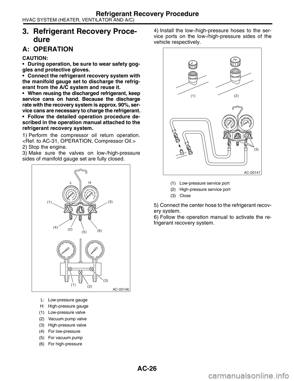
3) Make sure the valves on low-/high-pressure
sides of manifold gauge set are fully closed.4) Install the low-/high-pressure hoses to the ser-
vice ports on the low-/high-pressure sides of the
vehicle respectively.
5) Connect the center hose to the refrigerant recov-
ery system.
6) Follow the operation manual to activate the re-
frigerant recovery system.
L: Low-pressure gauge
H: High-pressure gauge
(1) Low-pressure valve
(2) Vacuum pump valve
(3) High-pressure valve
(4) For low-pressure
(5) For vacuum pump
(6) For high-pressure
AC-00146
(2) (4)
(5)(6)
(3)(3)
(2) (1)H L
(1)
(1) Low-pressure service port
(2) High-pressure service port
(3) Close
AC-00147
(3) (2) (1)
Page 32 of 2870
AC-30
HVAC SYSTEM (HEATER, VENTILATOR AND A/C)
Refrigerant Leak Check
5. Refrigerant Leak Check
A: INSPECTION
1) Operate the A/C system for approx. 10 minutes,
and confirm that the high-pressure side shows at
least 690 kPa (7.03 kg/cm
2, 100 psi). Then stop the
engine to start the leak test.
2) Starting from the connection between the high-
pressure pipe and evaporator, check the system for
leaks along the high-pressure side through the
compressor. The following items must be checked
thoroughly.
3) Check the joint and seam between the pressure
switch (triple pressure switch) and high-pressure
pipe.
4) Check the connections between the condenser
and pipes, and welded joints on the condenser.
The leak tester may detect the oil on the condenser
fins as a leak.
5) Check the joint between the compressor and
hoses.
6) Check the machined area of compressor and
other joints on the compressor.
7) Check the compressor shaft seal at the area
near the center of compressor clutch pulley.
Some shaft seals show a slight amount of leakage
about 28 g (1.0 oz) per year. This is not a problem.
8) Starting from the connection between the low-
pressure pipe and evaporator, check the system for
leakage along the low-pressure side through the
compressor. The following items must be checked
thoroughly.
Connection between two parts
Connection between the pipe and plate
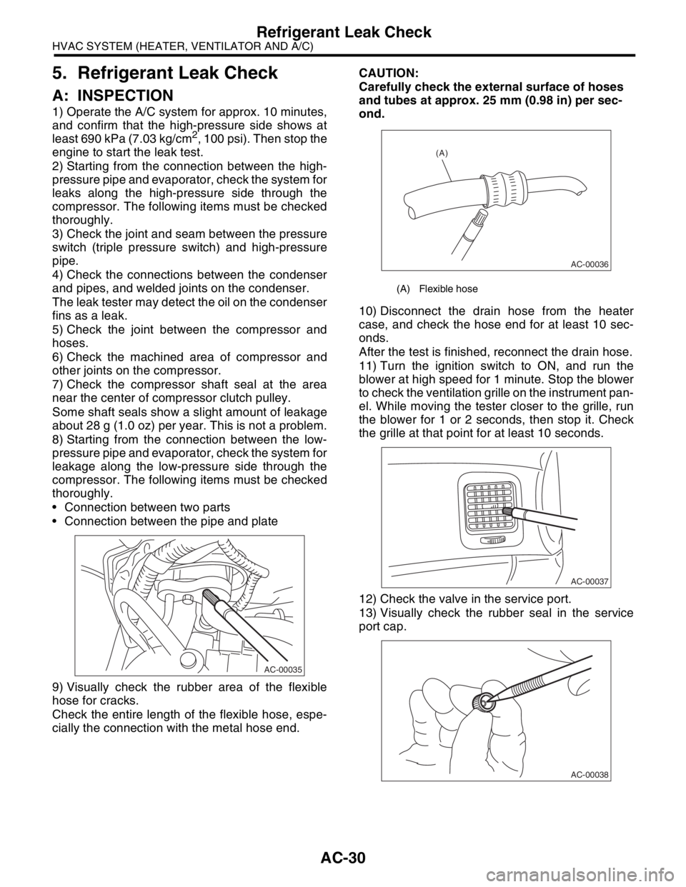
9) Visually check the rubber area of the flexible
hose for cracks.
Check the entire length of the flexible hose, espe-
cially the connection with the metal hose end.CAUTION:
Carefully check the external surface of hoses
and tubes at approx. 25 mm (0.98 in) per sec-
ond.
10) Disconnect the drain hose from the heater
case, and check the hose end for at least 10 sec-
onds.
After the test is finished, reconnect the drain hose.
11) Turn the ignition switch to ON, and run the
blower at high speed for 1 minute. Stop the blower
to check the ventilation grille on the instrument pan-
el. While moving the tester closer to the grille, run
the blower for 1 or 2 seconds, then stop it. Check
the grille at that point for at least 10 seconds.
12) Check the valve in the service port.
13) Visually check the rubber seal in the service
port cap.
AC-00035
(A) Flexible hose
AC-00036
(A)
AC-00037
AC-00038
Page 38 of 2870
AC-36
HVAC SYSTEM (HEATER, VENTILATOR AND A/C)
Compressor
11.Compressor
A: INSPECTION
1. MAGNETIC CLUTCH CLEARANCE
1) Check the clearance of the entire circumference
around the drive plate and pulley.
Standard:
0.3 — 0.6 mm (0.0118 — 0.0236 in)
2. MAGNETIC CLUTCH OPERATION
1) Disconnect the compressor connector.
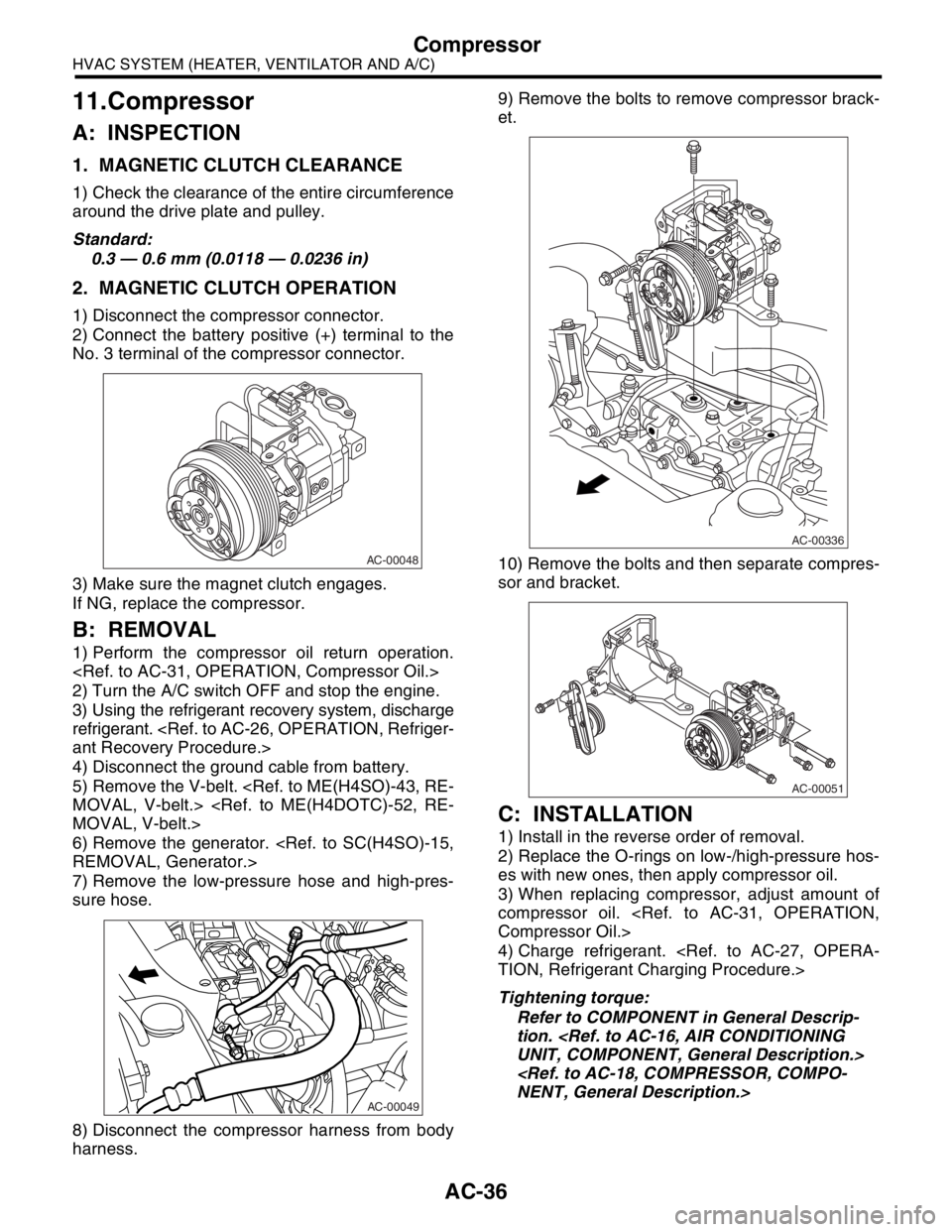
2) Connect the battery positive (+) terminal to the
No. 3 terminal of the compressor connector.
3) Make sure the magnet clutch engages.
If NG, replace the compressor.
B: REMOVAL
1) Perform the compressor oil return operation.
2) Turn the A/C switch OFF and stop the engine.
3) Using the refrigerant recovery system, discharge
refrigerant.
4) Disconnect the ground cable from battery.
5) Remove the V-belt.
6) Remove the generator.
7) Remove the low-pressure hose and high-pres-
sure hose.
8) Disconnect the compressor harness from body
harness.9) Remove the bolts to remove compressor brack-
et.
10) Remove the bolts and then separate compres-
sor and bracket.
C: INSTALLATION
1) Install in the reverse order of removal.
2) Replace the O-rings on low-/high-pressure hos-
es with new ones, then apply compressor oil.
3) When replacing compressor, adjust amount of
compressor oil.
4) Charge refrigerant.
Tightening torque:
Refer to COMPONENT in General Descrip-
tion.
AC-00048
AC-00049
AC-00336
AC-00051
Page 39 of 2870
AC-37
HVAC SYSTEM (HEATER, VENTILATOR AND A/C)
Condenser
12.Condenser
A: REMOVAL
1) Using the refrigerant recovery system, discharge
refrigerant.
2) Disconnect the ground cable from battery.
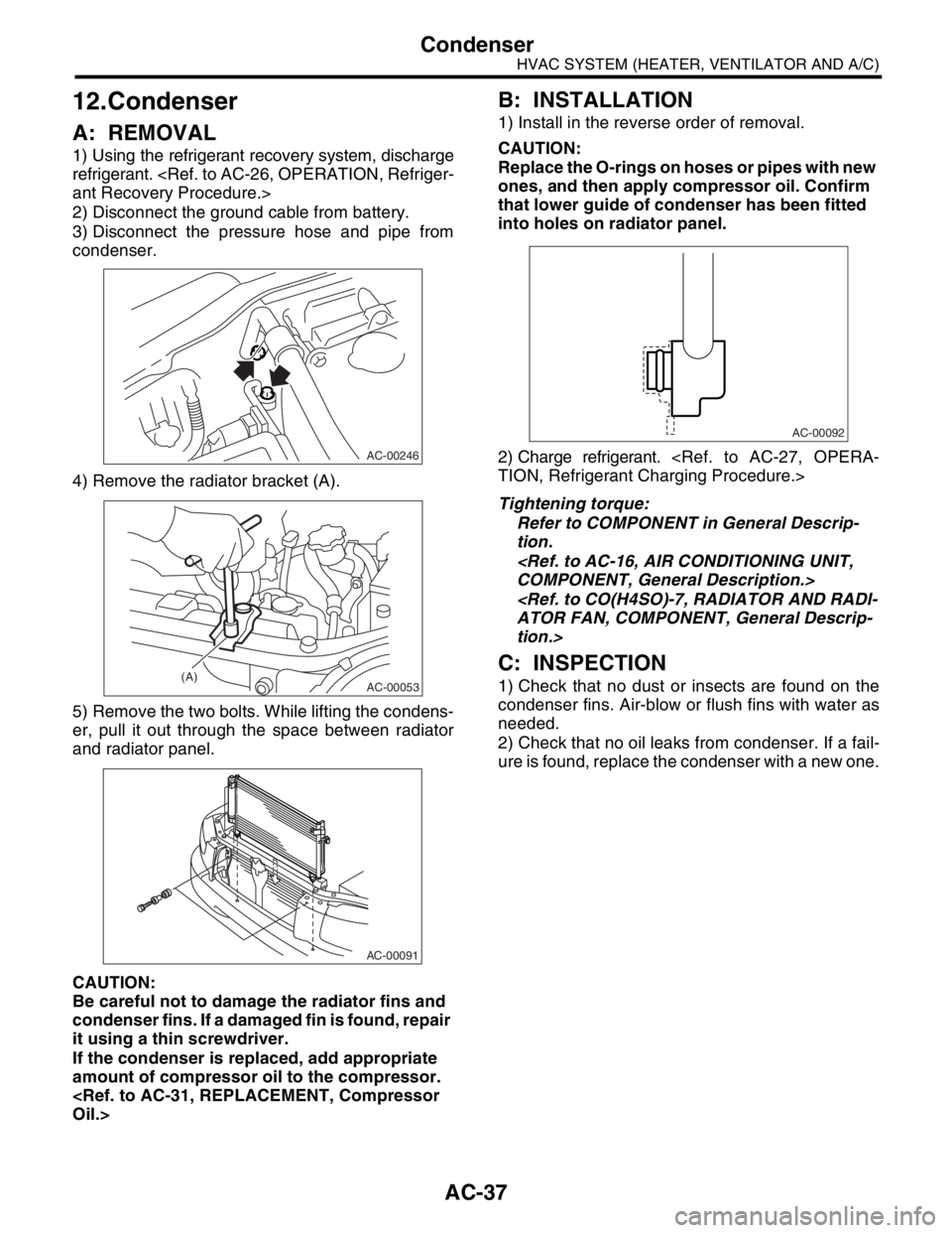
3) Disconnect the pressure hose and pipe from
condenser.
4) Remove the radiator bracket (A).
5) Remove the two bolts. While lifting the condens-
er, pull it out through the space between radiator
and radiator panel.
CAUTION:
Be careful not to damage the radiator fins and
condenser fins. If a damaged fin is found, repair
it using a thin screwdriver.
If the condenser is replaced, add appropriate
amount of compressor oil to the compressor.
B: INSTALLATION
1) Install in the reverse order of removal.
CAUTION:
Replace the O-rings on hoses or pipes with new
ones, and then apply compressor oil. Confirm
that lower guide of condenser has been fitted
into holes on radiator panel.
2) Charge refrigerant.
Tightening torque:
Refer to COMPONENT in General Descrip-
tion.
tion.>
C: INSPECTION
1) Check that no dust or insects are found on the
condenser fins. Air-blow or flush fins with water as
needed.
2) Check that no oil leaks from condenser. If a fail-
ure is found, replace the condenser with a new one.
AC-00246
AC-00053(A)
AC-00091
AC-00092
Page 43 of 2870
AC-41
HVAC SYSTEM (HEATER, VENTILATOR AND A/C)
Hose and Tube
16.Hose and Tube
A: REMOVAL
CAUTION:
When disconnecting/connecting hoses, do not
apply excessive force to them. Confirm that no
torsion and excessive tension exists after install-
ing.
Seal the disconnected hose with a plug or vi-
nyl tape to prevent foreign matters from enter-
ing.
1) Disconnect the ground cable from battery.
2) Using the refrigerant recovery system, dis-
charge refrigerant.
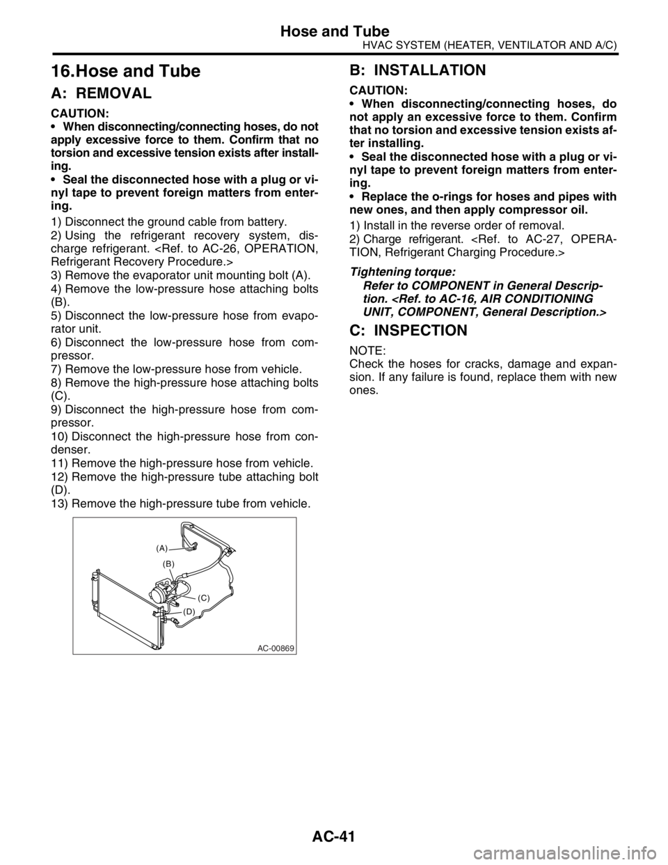
3) Remove the evaporator unit mounting bolt (A).
4) Remove the low-pressure hose attaching bolts
(B).
5) Disconnect the low-pressure hose from evapo-
rator unit.
6) Disconnect the low-pressure hose from com-
pressor.
7) Remove the low-pressure hose from vehicle.
8) Remove the high-pressure hose attaching bolts
(C).
9) Disconnect the high-pressure hose from com-
pressor.
10) Disconnect the high-pressure hose from con-
denser.
11) Remove the high-pressure hose from vehicle.
12) Remove the high-pressure tube attaching bolt
(D).
13) Remove the high-pressure tube from vehicle.
B: INSTALLATION
CAUTION:
When disconnecting/connecting hoses, do
not apply an excessive force to them. Confirm
that no torsion and excessive tension exists af-
ter installing.
Seal the disconnected hose with a plug or vi-
nyl tape to prevent foreign matters from enter-
ing.
Replace the o-rings for hoses and pipes with
new ones, and then apply compressor oil.
1) Install in the reverse order of removal.
2) Charge refrigerant.
Tightening torque:
Refer to COMPONENT in General Descrip-
tion.
C: INSPECTION
NOTE:
Check the hoses for cracks, damage and expan-
sion. If any failure is found, replace them with new
ones.
AC-00869
(A)
(C) (B)
(D)
Page 386 of 2870

IDI-2
INSTRUMENTATION/DRIVER INFO
General Description
1. General Description
A: SPECIFICATION
B: CAUTION
Be careful not to damage meters and instrument panel.
Be careful not to damage meter glasses.
Make sure that electrical connector is connected securely.
After installation, make sure that each meter operates normally.
Use gloves to avoid damage and getting fingerprints on the glass surface and meter surfaces.
Do not apply excessive force to the printed circuit.
Do not drop or otherwise apply impact.
C: PREPARATION TOOL
1. GENERAL TOOL
Combination meterSpeedometer Electric pulse type
Temperature gauge Cross coil type
Fuel gauge Cross coil type
Tachometer Electric pulse type
Turn signal indicator light 14 V — 2 W
Charge indicator light 14 V — 1.4 W
Oil pressure indicator light LED
ABS warning light 14 V — 1.4 W
Malfunction indicator light LED
HI-beam indicator light 14 V — 2 W
Door open warning light LED
Seat belt warning light LED
Brake fluid and parking brake warning
light14 V — 2 W
FWD indicator light LED
AIRBAG warning light LED
Meter illumination light 14 V — 3.4 W, 14 V — 2 W
AT OIL TEMP. warning light LED
LO indicator light LED
HOLD indicator light LED
Immobilizer indicator light LED
Rear differential oil temperature warn-
ing light14 V — 2 W
Cruise indicator light 14 V — 1.4 W
Rear fog light indicator light 14 V — 2 W
POWER indicator light 14 V — 1.4 W
Low fuel warning light LED
AT select lever position indicator light 14 V — 100 mA
LCD back light 14 V — 1.4 W
TOOL NAME REMARKS
Circuit tester Used for measuring resistance and voltage.