2004 SUBARU FORESTER Hill holder
[x] Cancel search: Hill holderPage 721 of 2870

RM-6
RECOMMENDED MATERIAL
Recommended Materials
8. ADHESIVES
Use the adhesives shown in the table below, or equivalent.
Grease MT main shaft FX 2200 clutch grease 000040901 —
Clutch master cylinder
push rodSlicolube G-40M 004404003 —
Gear shift lever
Select lever
Clutch operating cyl-
inder
Accelerator pedal
Clutch pedal
Brake pedal
Hill holder
Clutch bearing
Clutch release lever
Steering shaft bear-
ingSUNLIGHT2 003602010 —
Steering gearbox Valiant grease M-2 003608001 —
Disc brake Niglube RX-2 K0779GA102 —
Drum brake
Drum brake wheel
cylinderMolykote No. 7439 003602001 —
Brake pad
Brake shoeMolykote AS-880N K0777YA010 —
Front axle AARi One luber C — —
Front axle AC HTBJ — —
Rear axle BJ Molylex No. 2 003601001 —
Rear axle EBJ NTG2218 — —
Rear axle DOJ VU-3A702 23223GA050 —
Water pump
Door latch
Door strikerSlicolube G-30M 004404002 —
Adhesive Application point Recommended Item number Alternative
Adhesive Windshield and body Dow Automotive’s
Adhesive: Gurit-ESSEX
Betaseal 1502 or equivalent
Glass primer: Betawipe VP
04604 or Betawipe 5001
Paint surface primer: Betap-
rime 5402——
Soft vinyl Cemedine 540 — 3M’s EC-776 EC-847 or EC-1022
(Spray type)
Momentary sealant Cemedine 3000 — Armstrong’s Eastman 910
Inner rearview mirror
baseREPAIR KIT IN MR 65029FC000 — Grease Application point Recommended Item number Alternative
Page 738 of 2870

PERIODIC MAINTENANCE SERVICE
PM
Page
1. General Description ....................................................................................2
2. Schedule .....................................................................................................3
3. Engine Oil....................................................................................................7
4. Engine Oil Filter...........................................................................................9
5. Spark Plugs ...............................................................................................10
6. V-belt .........................................................................................................11
7. Timing Belt ................................................................................................13
8. Fuel Line ...................................................................................................17
9. Fuel Filter ..................................................................................................18
10. Air Cleaner Element ..................................................................................19
11. Cooling System .........................................................................................20
12. Engine Coolant..........................................................................................21
13. Clutch System ...........................................................................................23
14. Transmission Gear Oil ..............................................................................24
15. Hill-holder System .....................................................................................25
16. ATF ...........................................................................................................26
17. Front & Rear Differential Oil ......................................................................28
18. Brake Line .................................................................................................30
19. Brake Fluid ................................................................................................32
20. Disc Brake Pads and Discs .......................................................................33
21. Brake Linings and Drums ..........................................................................34
22. Suspension ...............................................................................................36
23. Wheel Bearing...........................................................................................38
24. Axle Boots & Joints ...................................................................................39
25. Tire Rotation..............................................................................................40
26. Steering System (Power Steering) ............................................................41
Page 740 of 2870

PM-3
PERIODIC MAINTENANCE SERVICE
Schedule
2. Schedule
A: MAINTENANCE SCHEDULE 1
1. FOR EUROPE AREA
For periodic maintenance of over 120,000 km (75,000 miles) or 96 months, carry out inspection by referring
to the following table. For a maintenance period gone beyond these tables, apply them repeatedly as a set
of 120,000 km (75,000 miles) or 96 months.
Symbols used:
R: Replace
I: Inspection
(I): Recommended service for safe vehicle operation.
N
OTE:
(1) When the vehicle is used in extremely dusty conditions, the air cleaner element should be replaced more often.
(2) ATF filter is a maintenance free part. ATF filter needs replacement, when it is physically damaged or ATF leaked.Maintenance interval
[Number of months or km (miles), whichever occurs first]
Month 1224364860728496
Remarks ×1,000 km 1.6 5 15 30 45 60 75 90 105 120
×1,000 miles 1 3 9 19 28 38 47 56 66 75
1Engine oil RRRRRRRR
2Engine oil filter RRRRRRRR
3 Spark plug For Turbo R
Others RRRR
4Drive belt(s) IIIIIIII
5Camshaft drive belt RRRR
6Fuel line IIII
7 Fuel filter R R
8 Air cleaner element I R I R I R I R
9Cooling system IIII
10Coolant RRRR
11Clutch system IIII
12Hill-holder system IIII
13 Transmission oil I R I R
14 ATF I R I R
15 Front & rear differential I R I R
16Brake line IIII
17Brake fluid RRRR
18Disk brake pads & discs IIIIIIII
19Brake linings & drums IIII
20Parking brake IIII
21Suspension IIII
22 Wheel bearing(I)
23Axle boot & joint IIIIIIII
24Steering system IIII
Page 741 of 2870

PM-4
PERIODIC MAINTENANCE SERVICE
Schedule
2. EXCEPT FOR EUROPE AREA
For periodic maintenance of over 50,000 km (30,000 miles) or 48 months, carry out inspections by referring
to the following tables. For a maintenance period gone beyond these tables, apply them repeatedly as a set
of 50,000 km (30,000 miles) or 48 months.
For periodic maintenance of over 100,000 km (60,000 miles) or 48 months, carry out inspections by referring
to the following tables. For a maintenance period gone beyond these tables, apply them repeatedly as a set
of 100,000 km (60,000 miles) or 48 months.
Symbols used:
R: Replace
I: Inspection
(I): Recommended service for safe vehicle operation.
N
OTE:
(1) When the vehicle is used in extremely dusty conditions, the air cleaner element should be replaced more often.
(2) ATF filter is a maintenance free part. ATF filter needs replacement, when it is physically damaged or ATF leaked.Maintenance Interval
[Number of months or km (miles), whichever occurs first]
Months 12 24 36 48
Remarks ×1,000 km 5 12.5 25 37.5 50
×1,000 miles 3 7.5 15 22.5 30
1 Engine oil R R R R
2 Engine oil filter R R R R
Maintenance Interval
[Number of months or km (miles), whichever occurs first]
Months 12 24 36 48
Remarks ×1,000 km 1.6 25 50 75 100
×1,000 miles 1 15 30 45 60
3 Spark plugs For Turbo R
Others R R R R
4Drive belt(s) IIII
5 Camshaft drive belt R
6 Fuel line I I
7 Fuel filter R R
8 Air cleaner element I R I R
9 Cooling system I I
10 Coolant R R
11 Clutch system I I I I I
12 Hill-holder system I I I I I
13 Transmission oil R R
14 ATF R R
15 Front & rear differential oil R R
16 Brake line I I
17 Brake fluid R R
18 Disc brake pads & discs I I I I
19 Brake linings and drums I I
20 Parking brake I I I I
21 Suspension I I I I
22 Wheel bearing (I)
23 Axle boots & joints I I I I
24 Steering system (Power steering) I I I I
Page 762 of 2870

PM-25
PERIODIC MAINTENANCE SERVICE
Hill-holder System
15.Hill-holder System
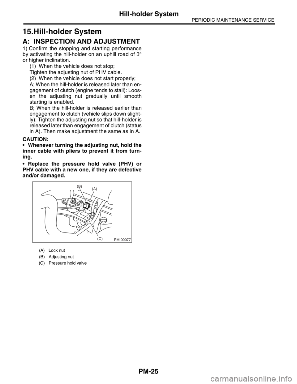
A: INSPECTION AND ADJUSTMENT
1) Confirm the stopping and starting performance
by activating the hill-holder on an uphill road of 3°
or higher inclination.
(1) When the vehicle does not stop;
Tighten the adjusting nut of PHV cable.
(2) When the vehicle does not start properly;
A; When the hill-holder is released later than en-
gagement of clutch (engine tends to stall): Loos-
en the adjusting nut gradually until smooth
starting is enabled.
B; When the hill-holder is released earlier than
engagement to clutch (vehicle slips down slight-
ly): Tighten the adjusting nut so that hill-holder is
released later than engagement of clutch (status
in A). Then make adjustment the same as in A.
CAUTION:
Whenever turning the adjusting nut, hold the
inner cable with pliers to prevent it from turn-
ing.
Replace the pressure hold valve (PHV) or
PHV cable with a new one, if they are defective
and/or damaged.
(A) Lock nut
(B) Adjusting nut
(C) Pressure hold valve
(C) (B)
(A)
PM-00077
Page 2860 of 2870

CL-34
CLUTCH SYSTEM
Clutch Pedal
10.Clutch Pedal
A: REMOVAL
1. LHD MODEL
1) Remove the steering column.
2) Disconnect the connectors from stop light switch
and clutch switch.
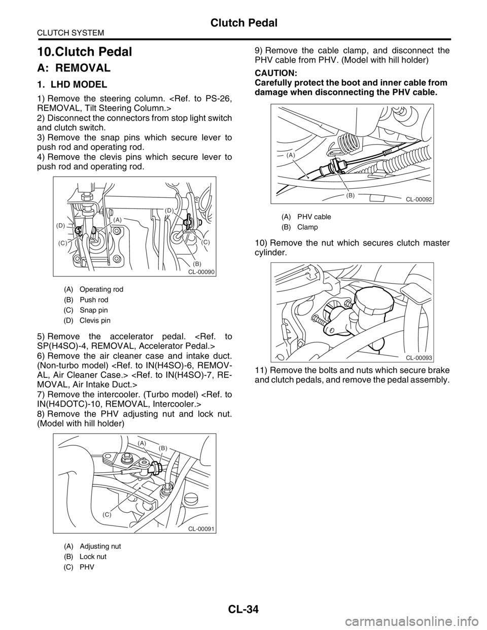
3) Remove the snap pins which secure lever to
push rod and operating rod.
4) Remove the clevis pins which secure lever to
push rod and operating rod.
5) Remove the accelerator pedal.
6) Remove the air cleaner case and intake duct.
(Non-turbo model)
7) Remove the intercooler. (Turbo model)
8) Remove the PHV adjusting nut and lock nut.
(Model with hill holder)9) Remove the cable clamp, and disconnect the
PHV cable from PHV. (Model with hill holder)
CAUTION:
Carefully protect the boot and inner cable from
damage when disconnecting the PHV cable.
10) Remove the nut which secures clutch master
cylinder.
11) Remove the bolts and nuts which secure brake
and clutch pedals, and remove the pedal assembly.
(A) Operating rod
(B) Push rod
(C) Snap pin
(D) Clevis pin
(A) Adjusting nut
(B) Lock nut
(C) PHV
(D)
(B)(C)
(C) (D)(A)
CL-00090
CL-00091
(C)(B) (A)
(A) PHV cable
(B) Clamp
(B) (A)
CL-00092
CL-00093
Page 2861 of 2870

CL-35
CLUTCH SYSTEM
Clutch Pedal
2. RHD MODEL
1) Disconnect the ground cable from battery.
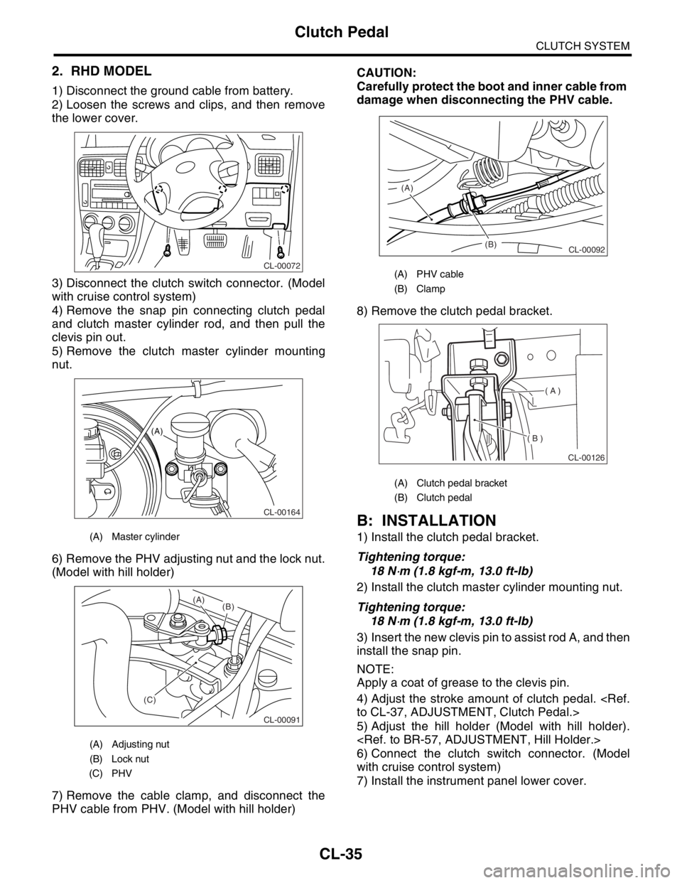
2) Loosen the screws and clips, and then remove
the lower cover.
3) Disconnect the clutch switch connector. (Model
with cruise control system)
4) Remove the snap pin connecting clutch pedal
and clutch master cylinder rod, and then pull the
clevis pin out.
5) Remove the clutch master cylinder mounting
nut.
6) Remove the PHV adjusting nut and the lock nut.
(Model with hill holder)
7) Remove the cable clamp, and disconnect the
PHV cable from PHV. (Model with hill holder)CAUTION:
Carefully protect the boot and inner cable from
damage when disconnecting the PHV cable.
8) Remove the clutch pedal bracket.
B: INSTALLATION
1) Install the clutch pedal bracket.
Tightening torque:
18 N
⋅m (1.8 kgf-m, 13.0 ft-lb)
2) Install the clutch master cylinder mounting nut.
Tightening torque:
18 N
⋅m (1.8 kgf-m, 13.0 ft-lb)
3) Insert the new clevis pin to assist rod A, and then
install the snap pin.
NOTE:
Apply a coat of grease to the clevis pin.
4) Adjust the stroke amount of clutch pedal.
5) Adjust the hill holder (Model with hill holder).
6) Connect the clutch switch connector. (Model
with cruise control system)
7) Install the instrument panel lower cover.
(A) Master cylinder
(A) Adjusting nut
(B) Lock nut
(C) PHV
CL-00072
CL-00164
(A)
CL-00091
(C)(B) (A)
(A) PHV cable
(B) Clamp
(A) Clutch pedal bracket
(B) Clutch pedal
(B) (A)
CL-00092
( A )
( B )
CL-00126
Page 2863 of 2870

CL-37
CLUTCH SYSTEM
Clutch Pedal
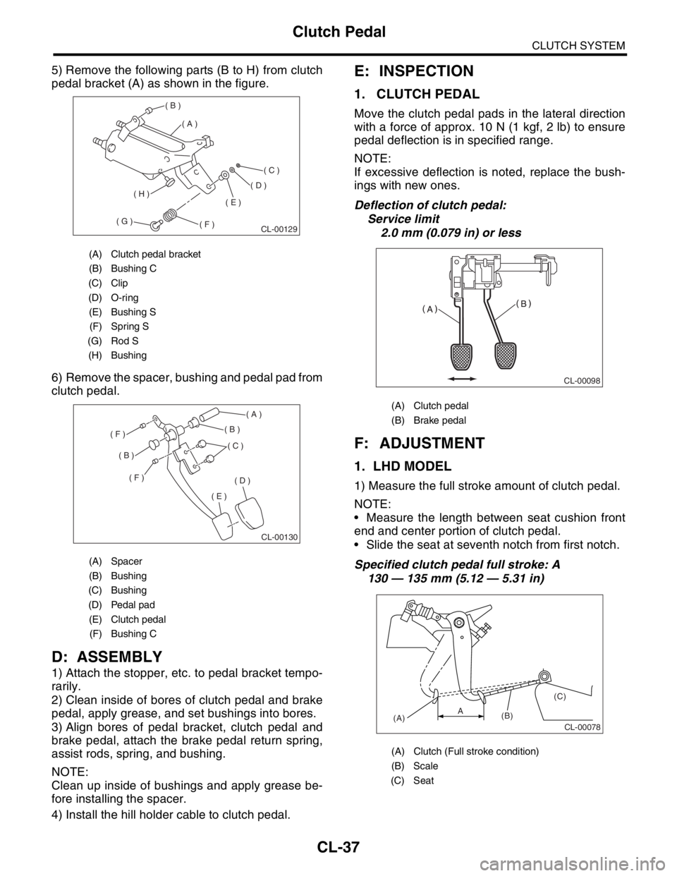
5) Remove the following parts (B to H) from clutch
pedal bracket (A) as shown in the figure.
6) Remove the spacer, bushing and pedal pad from
clutch pedal.
D: ASSEMBLY
1) Attach the stopper, etc. to pedal bracket tempo-
rarily.
2) Clean inside of bores of clutch pedal and brake
pedal, apply grease, and set bushings into bores.
3) Align bores of pedal bracket, clutch pedal and
brake pedal, attach the brake pedal return spring,
assist rods, spring, and bushing.
NOTE:
Clean up inside of bushings and apply grease be-
fore installing the spacer.
4) Install the hill holder cable to clutch pedal.
E: INSPECTION
1. CLUTCH PEDAL
Move the clutch pedal pads in the lateral direction
with a force of approx. 10 N (1 kgf, 2 lb) to ensure
pedal deflection is in specified range.
NOTE:
If excessive deflection is noted, replace the bush-
ings with new ones.
Deflection of clutch pedal:
Service limit
2.0 mm (0.079 in) or less
F: ADJUSTMENT
1. LHD MODEL
1) Measure the full stroke amount of clutch pedal.
NOTE:
Measure the length between seat cushion front
end and center portion of clutch pedal.
Slide the seat at seventh notch from first notch.
Specified clutch pedal full stroke: A
130 — 135 mm (5.12 — 5.31 in)
(A) Clutch pedal bracket
(B) Bushing C
(C) Clip
(D) O-ring
(E) Bushing S
(F) Spring S
(G) Rod S
(H) Bushing
(A) Spacer
(B) Bushing
(C) Bushing
(D) Pedal pad
(E) Clutch pedal
(F) Bushing C
( A )
( B )
( C )
( D )
( E )
( F )( G )
( H )
CL-00129
( A )
( B )
( B )
( C )
( D )
( E )
( F )
( F )
CL-00130
(A) Clutch pedal
(B) Brake pedal
(A) Clutch (Full stroke condition)
(B) Scale
(C) Seat
CL-00098
CL-00078(A)(B)(C)A