Page 770 of 2870

PM-33
PERIODIC MAINTENANCE SERVICE
Disc Brake Pads and Discs
20.Disc Brake Pads and Discs
A: INSPECTION
1. DISC BRAKE PAD AND DISC
1) Lift-up the vehicle. Then remove the wheels.
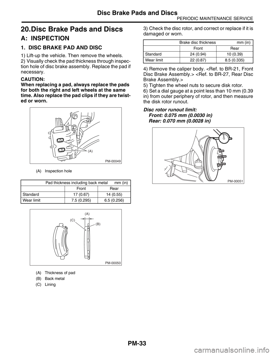
2) Visually check the pad thickness through inspec-
tion hole of disc brake assembly. Replace the pad if
necessary.
CAUTION:
When replacing a pad, always replace the pads
for both the right and left wheels at the same
time. Also replace the pad clips if they are twist-
ed or worn.3) Check the disc rotor, and correct or replace if it is
damaged or worn.
4) Remove the caliper body.
Disc Brake Assembly.>
Brake Assembly.>
5) Tighten the wheel nuts to secure disk rotor.
6) Set a dial gauge at a point less than 10 mm (0.39
in) from outer periphery of rotor, and then measure
the disk rotor runout.
Disc rotor runout limit:
Front: 0.075 mm (0.0030 in)
Rear: 0.070 mm (0.0028 in)
(A) Inspection hole
Pad thickness including back metal mm (in)
Front Rear
Standard 17 (0.67) 14 (0.55)
Wear limit 7.5 (0.295) 6.5 (0.256)
(A) Thickness of pad
(B) Back metal
(C) Lining
PM-00049
(A)
PM-00050
(A)
(C)
(B)
Brake disc thickness mm (in)
Front Rear
Standard 24 (0.94) 10 (0.39)
Wear limit 22 (0.87) 8.5 (0.335)
PM-00051
Page 771 of 2870

PM-34
PERIODIC MAINTENANCE SERVICE
Brake Linings and Drums
21.Brake Linings and Drums
A: INSPECTION
1. REAR DRUM BRAKE
1) Remove the brake drum, and check that there is
no fluid leakage from wheel cylinder.
If there is fluid leakage from wheel cylinder, inspect
the wheel cylinder, and then repair or replace it.
2) Inspect the brake shoes for damage or deformi-
ties and check brake linings for wear.
CAUTION:
Always replace both leading and trailing
brake shoes for the right and left wheels at the
same time.
When either the right and left brake assembly
is replaced, always replace the leading shoe
and trailing shoe of the other.
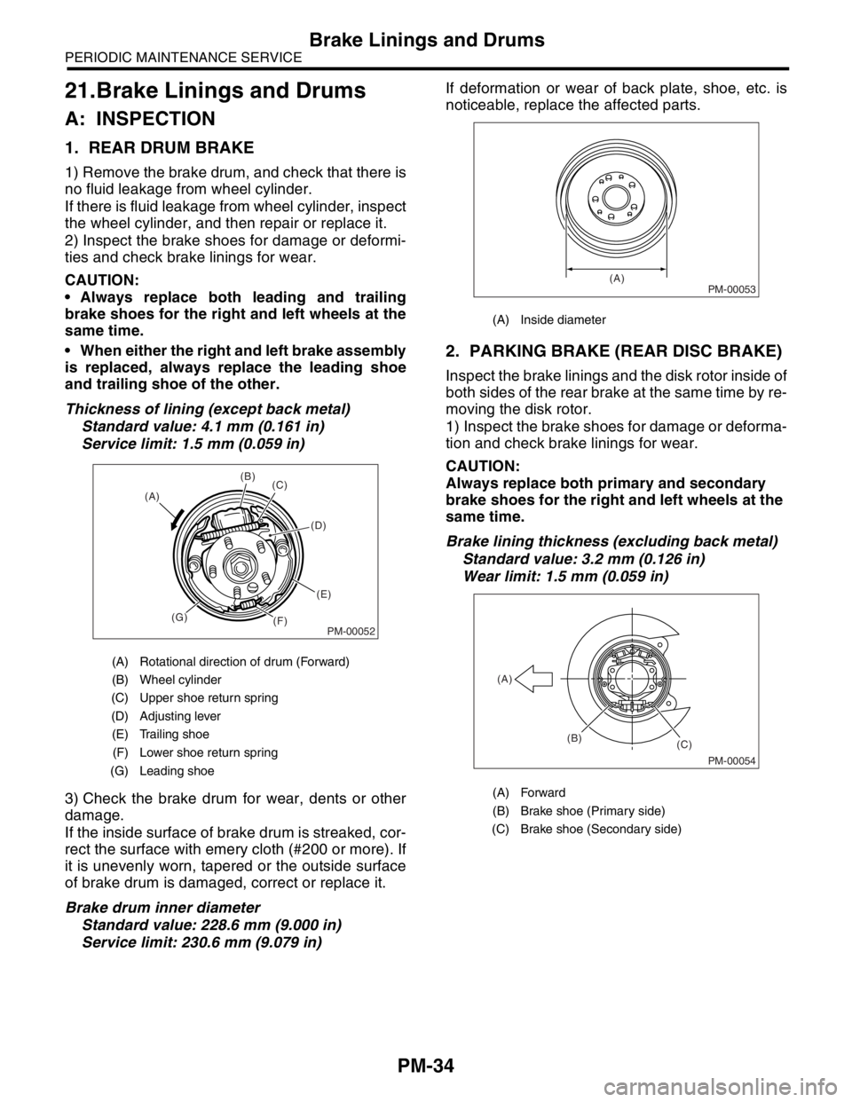
Thickness of lining (except back metal)
Standard value: 4.1 mm (0.161 in)
Service limit: 1.5 mm (0.059 in)
3) Check the brake drum for wear, dents or other
damage.
If the inside surface of brake drum is streaked, cor-
rect the surface with emery cloth (#200 or more). If
it is unevenly worn, tapered or the outside surface
of brake drum is damaged, correct or replace it.
Brake drum inner diameter
Standard value: 228.6 mm (9.000 in)
Service limit: 230.6 mm (9.079 in)If deformation or wear of back plate, shoe, etc. is
noticeable, replace the affected parts.
2. PARKING BRAKE (REAR DISC BRAKE)
Inspect the brake linings and the disk rotor inside of
both sides of the rear brake at the same time by re-
moving the disk rotor.
1) Inspect the brake shoes for damage or deforma-
tion and check brake linings for wear.
CAUTION:
Always replace both primary and secondary
brake shoes for the right and left wheels at the
same time.
Brake lining thickness (excluding back metal)
Standard value: 3.2 mm (0.126 in)
Wear limit: 1.5 mm (0.059 in)
(A) Rotational direction of drum (Forward)
(B) Wheel cylinder
(C) Upper shoe return spring
(D) Adjusting lever
(E) Trailing shoe
(F) Lower shoe return spring
(G) Leading shoe
PM-00052
(B)
(C)
(D)
(E)
(F) (G) (A)
(A) Inside diameter
(A) Forward
(B) Brake shoe (Primary side)
(C) Brake shoe (Secondary side)
PM-00053(A)
PM-00054
(B)
(C) (A)
Page 772 of 2870

PM-35
PERIODIC MAINTENANCE SERVICE
Brake Linings and Drums
2) Check the disk rotor for wear, dents or other
damage. If the inside surface of disk rotor is
streaked, correct the surface with emery cloth
(#200 or more). If it is unevenly worn or tapered,
correct or replace it.
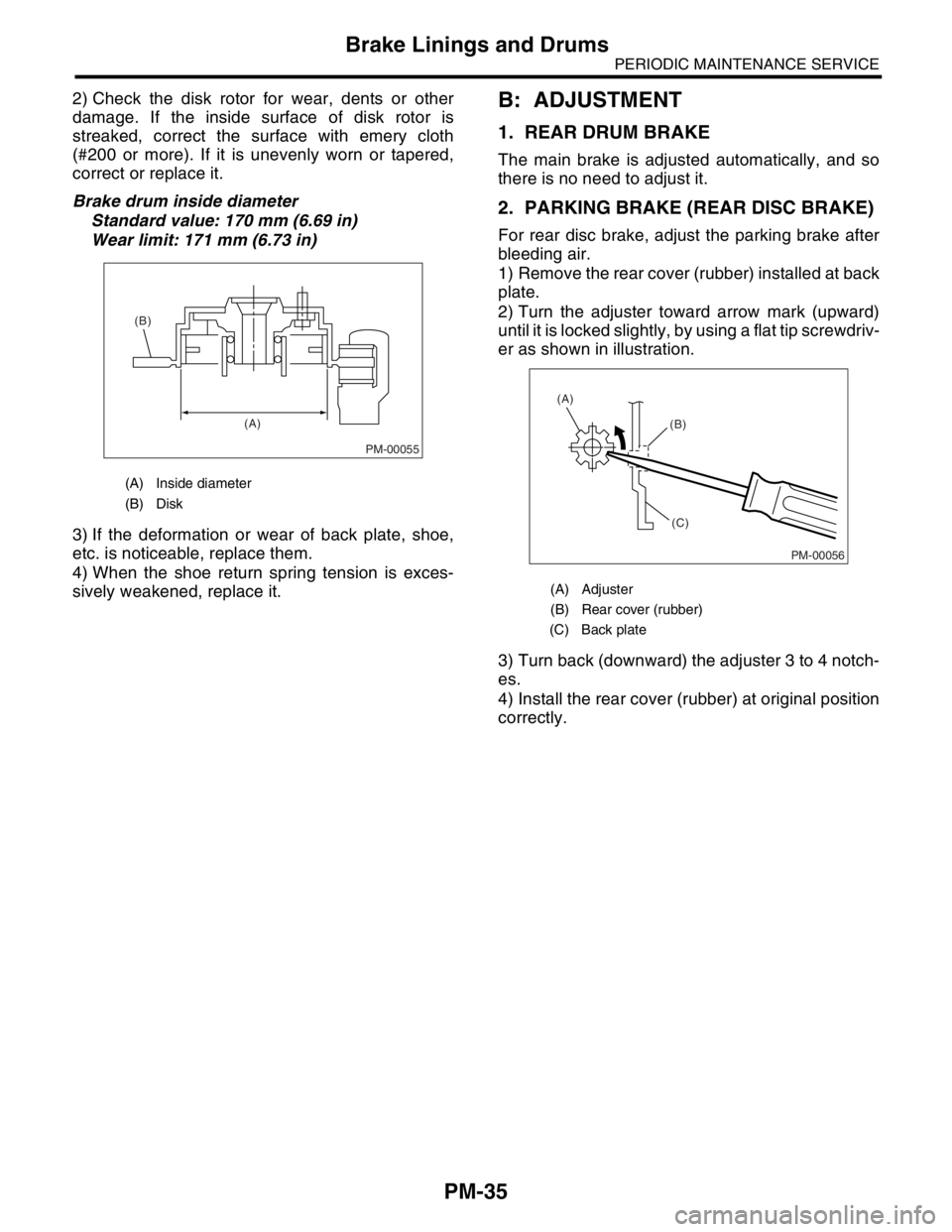
Brake drum inside diameter
Standard value: 170 mm (6.69 in)
Wear limit: 171 mm (6.73 in)
3) If the deformation or wear of back plate, shoe,
etc. is noticeable, replace them.
4) When the shoe return spring tension is exces-
sively weakened, replace it.B: ADJUSTMENT
1. REAR DRUM BRAKE
The main brake is adjusted automatically, and so
there is no need to adjust it.
2. PARKING BRAKE (REAR DISC BRAKE)
For rear disc brake, adjust the parking brake after
bleeding air.
1) Remove the rear cover (rubber) installed at back
plate.
2) Turn the adjuster toward arrow mark (upward)
until it is locked slightly, by using a flat tip screwdriv-
er as shown in illustration.
3) Turn back (downward) the adjuster 3 to 4 notch-
es.
4) Install the rear cover (rubber) at original position
correctly.
(A) Inside diameter
(B) Disk
PM-00055
(A) (B)
(A) Adjuster
(B) Rear cover (rubber)
(C) Back plate
PM-00056
(B)
(C) (A)
Page 2314 of 2870

4AT-2
AUTOMATIC TRANSMISSION
General Description
1. General Description
A: SPECIFICATION
1. TORQUE CONVERTER CLUTCH
2. OIL PUMP
3. TRANSMISSION CONTROL ELEMENT
4. TRANSMISSION GEAR RATIO5. PLANETARY GEAR AND PLATE
Model2.0 L
Non-
turbo2.5 L
Non-
turbo2.0 L
Tu r b o2.5 L
Tu r b o
Ty p eSymmetric, 3 element, single stage, 2 phase
torque converter
Stall torque
ratio2.0 —
2.21.9 —
2.11.85 —
2.152.05 —
2.35
Nominal
diameter246 mm (9.69 in)
Stall speed
(at sea level)2,000 —
2,500
rpm2,100 —
2,600
rpm2,600 —
3,300
rpm2,700 —
3,200
rpm
One-way
clutchSprague type one-way clutch
Type Pracoid constant-displacement pump
Driving method Driven by engine
Number of teethInner rotor 9
Outer rotor 10
Ty p e4-forward, 1-reverse, double-row plan-
etary gears
Multi-plate clutch 3 sets
Multi-plate brake 2 sets
One-way clutch
(sprague type)1 sets
Gear ratio
1st 2.785
2nd 1.545
3rd 1.000
4th 0.694
Rev 2.272
Model2.0 L Non-
turbo2.5 L Non-
turboTu r b o
Tooth num-
ber of front
sun gear33
Front pinion
number of
teeth21
Front inter-
nal gear
number of
teeth75
Tooth num-
ber of rear
sun gear42
Rear pinion
number of
teeth17
Tooth num-
ber of rear
internal gear75
Drive &
driven plate
number of
high clutch45
Drive &
driven plate
number of
low clutch467
Drive &
driven plate
number of
reverse
clutch2
Drive &
driven plate
number of 2-
4 brake34
Drive &
driven plate
number of
low &
reverse
brake467