2004 SUBARU FORESTER fuel
[x] Cancel search: fuelPage 268 of 2870

LI-14
LIGHTING SYSTEM
Headlight Assembly
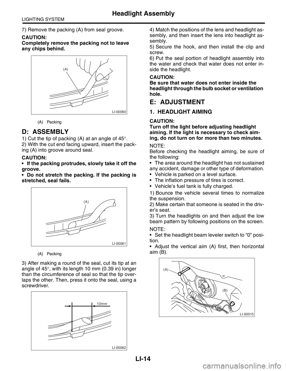
7) Remove the packing (A) from seal groove.
CAUTION:
Completely remove the packing not to leave
any chips behind.
D: ASSEMBLY
1) Cut the tip of packing (A) at an angle of 45°.
2) With the cut end facing upward, insert the pack-
ing (A) into groove around seal.
CAUTION:
If the packing protrudes, slowly take it off the
groove.
Do not stretch the packing. If the packing is
stretched, seal fails.
3) After making a round of the seal, cut its tip at an
angle of 45°, with its length 10 mm (0.39 in) longer
than the circumference of seal so that the tip over-
laps the other. Then, press it onto the seal, using a
screwdriver.4) Match the positions of the lens and headlight as-
sembly, and then insert the lens into headlight as-
sembly.
5) Secure the hook, and then install the clip and
screw.
6) Put the seal portion of headlight assembly into
the water and check that water does not enter in-
side the headlight.
CAUTION:
Be sure that water does not enter inside the
headlight through the bulb socket or ventilation
hole.
E: ADJUSTMENT
1. HEADLIGHT AIMING
CAUTION:
Turn off the light before adjusting headlight
aiming. If the light is necessary to check aim-
ing, do not turn on for more than two minutes.
NOTE:
Before checking the headlight aiming, be sure of
the following:
The area around the headlight has not sustained
any accident, damage or other type of deformation.
Vehicle is parked on a level surface.
The inflation pressure of tires is correct.
Vehicle’s fuel tank is fully charged.
1) Bounce the vehicle several times to normalize
the suspension.
2) Make certain that someone is seated in the driv-
er’s seat.
3) Turn the headlights on and then adjust the low
beam pattern by following positions on the screen.
NOTE:
Set the headlight beam leveler switch to “0” posi-
tion.
Adjust the vertical aim (A) first, then horizontal
aim (B).(A) Packing
(A) Packing
LI-00060
(A)
LI-00061
(A)
LI-00062
10mm
LI-00015
(A)
(B)
Page 385 of 2870

INSTRUMENTATION/DRIVER INFO
IDI
Page
1. General Description ....................................................................................2
2. Combination Meter System .........................................................................3
3. Combination Meter Assembly ...................................................................10
4. Speedometer.............................................................................................13
5. Tachometer ...............................................................................................14
6. Fuel Gauge ...............................................................................................15
7. Water Temperature Gauge .......................................................................16
8. Ambient Sensor.........................................................................................17
Page 386 of 2870

IDI-2
INSTRUMENTATION/DRIVER INFO
General Description
1. General Description
A: SPECIFICATION
B: CAUTION
Be careful not to damage meters and instrument panel.
Be careful not to damage meter glasses.
Make sure that electrical connector is connected securely.
After installation, make sure that each meter operates normally.
Use gloves to avoid damage and getting fingerprints on the glass surface and meter surfaces.
Do not apply excessive force to the printed circuit.
Do not drop or otherwise apply impact.
C: PREPARATION TOOL
1. GENERAL TOOL
Combination meterSpeedometer Electric pulse type
Temperature gauge Cross coil type
Fuel gauge Cross coil type
Tachometer Electric pulse type
Turn signal indicator light 14 V — 2 W
Charge indicator light 14 V — 1.4 W
Oil pressure indicator light LED
ABS warning light 14 V — 1.4 W
Malfunction indicator light LED
HI-beam indicator light 14 V — 2 W
Door open warning light LED
Seat belt warning light LED
Brake fluid and parking brake warning
light14 V — 2 W
FWD indicator light LED
AIRBAG warning light LED
Meter illumination light 14 V — 3.4 W, 14 V — 2 W
AT OIL TEMP. warning light LED
LO indicator light LED
HOLD indicator light LED
Immobilizer indicator light LED
Rear differential oil temperature warn-
ing light14 V — 2 W
Cruise indicator light 14 V — 1.4 W
Rear fog light indicator light 14 V — 2 W
POWER indicator light 14 V — 1.4 W
Low fuel warning light LED
AT select lever position indicator light 14 V — 100 mA
LCD back light 14 V — 1.4 W
TOOL NAME REMARKS
Circuit tester Used for measuring resistance and voltage.
Page 388 of 2870

IDI-4
INSTRUMENTATION/DRIVER INFO
Combination Meter System
B: INSPECTION
CAUTION:
When measuring voltage and resistance of the ECM, TCM, or each sensor, use a tapered pin with a
diameter of less than 0.64 mm (0.025 in) in order to avoid poor contact. Do not insert the pin more
than 2 mm (0.08 in).
1. SYMPTOM CHART
Symptom Repair order Reference
Combination meter assembly does not operate. (1) Power supply
(2) Ground circuit
GROUND CIRCUIT,
INSPECTION, Combi-
nation Meter System.>
Speedometer does not operate. (1) (MT model) Vehicle speed sensor
(AT model) TCM
(2) Harness
(3) SpeedometerMT model:
SPEED SENSOR,
INSPECTION, Combi-
nation Meter System.>
AT model:
SION CONTROL MOD-
ULE (TCM),
INSPECTION, Combi-
nation Meter System.>
Tachometer does not operate. (1) ECM
(2) Harness
(3) Tachometer
MODULE (ECM),
INSPECTION, Combi-
nation Meter System.>
Fuel gauge does not operate. (1) Fuel level sensor
(2) Harness
(3) Fuel gauge
SOR, INSPECTION,
Combination Meter
System.>
Water temperature gauge does not operate. (1) Engine coolant temperature sensor
(2) Harness
(3) Water temperature gauge
TEMPERATURE SEN-
SOR, INSPECTION,
Combination Meter
System.>
Outside temperature indicator does not operate. (1) Ambient sensor
(2) Harness
(3) Combination meter
TURE INDICATOR,
INSPECTION, Combi-
nation Meter System.>
Page 391 of 2870

IDI-7
INSTRUMENTATION/DRIVER INFO
Combination Meter System
5. CHECK ENGINE CONTROL MODULE (ECM)
6. CHECK FUEL LEVEL SENSOR
Step Check Yes No
1 CHECK ECM SIGNAL.
1) Start the engine.
2) Measure the voltage between ECM con-
nector and engine ground.
Connector & terminal
Non-turbo model
(B134) No. 10 (+) — Engine ground (
−):
Turbo model
(B134) No. 23 (+) — Engine ground (
−):Is the voltage 0 V ← → 14 V? Go to step 2.Check ECM.
Basic Diagnostics
Procedure.>
Basic Diagnostics
Procedure.>
2 CHECK HARNESS BETWEEN COMBINA-
TION METER AND ECM.
1) Turn the ignition switch to OFF.
2) Disconnect the connector from ECM and
combination meter.
3) Measure the resistance between ECM har-
ness connector and combination meter har-
ness connector.
Connector & terminal
Non-turbo model
(B134) No. 10 — (i10) No. 11:
Turbo model
(B134) No. 23 — (i10) No. 11:Is the resistance less than 10
Ω?Check the tachom-
eter.
Tachometer.>Repair the wiring
harness.
Step Check Yes No
1 CHECK FUEL LEVEL SENSOR.
1) Remove the fuel level sensor.
sor.>
2) Measure the resistance between fuel level
sensor terminals when setting the float to
FULL and EMPTY position.
Te r m i n a l s
No. 3 — No. 5:Is the resistance 0.5 to 2.5 Ω
(FULL) and 50 to 52 Ω
(EMPTY)?Go to step 2.Replace the fuel
level sensor.
2 CHECK FUEL SUB LEVEL SENSOR.
1) Remove the fuel sub level sensor.
Sensor.>
2) Measure the resistance between fuel sub
level sensor terminals when setting the float to
FULL and EMPTY position.
Te r m i n a l s
No. 1 — No. 2:Is the resistance 0.5 to 2.5 Ω
(FULL) and 42 to 44 Ω
(EMPTY)?Go to step 3.Replace the fuel
sub level sensor.
3 CHECK HARNESS BETWEEN FUEL SUB
LEVEL SENSOR AND COMBINATION
METER.
1) Disconnect the connector from combination
meter.
2) Measure the resistance between fuel sub
level sensor harness connector terminal and
combination meter harness connector termi-
nal.
Connector & terminal
(R59) No. 1 — (i11) No. 1:Is the resistance less than 10
Ω?Go to step 4.Repair the wiring
harness.
Page 392 of 2870

IDI-8
INSTRUMENTATION/DRIVER INFO
Combination Meter System
7. CHECK ENGINE COOLANT TEMPERATURE SENSOR
8. CHECK OUTSIDE TEMPERATURE INDICATOR
4 CHECK HARNESS BETWEEN FUEL LEVEL
SENSOR AND FUEL SUB LEVEL SENSOR.
Measure the resistance between fuel level sen-
sor harness connector terminal and fuel sub
level sensor harness connector terminal.
Connector & terminal
(R58) No. 3 — (R59) No. 2:Is the resistance less than 10
Ω?Go to step 5.Repair the wiring
harness.
5 CHECK FUEL LEVEL SENSOR GROUND
CIRCUIT.
Measure the resistance between fuel level sen-
sor harness connector terminal and chassis
ground.
Connector & terminal
(R58) No. 5 — Chassis ground:Is the resistance less than 10
Ω?Check the fuel
gauge.
TION, Fuel
Gauge.>Repair the wiring
harness.
Step Check Yes No
1 CHECK ENGINE COOLANT TEMPERATURE
SENSOR.
Check the engine coolant temperature sensor.
ture sensor OK?Go to step 2.Replace the
engine coolant
temperature sen-
sor.
2 CHECK HARNESS BETWEEN ENGINE
COOLANT TEMPERATURE SENSOR AND
COMBINATION METER.
1) Turn the ignition switch to OFF.
2) Disconnect the connector from engine cool-
ant temperature sensor and combination
meter.
3) Measure the resistance between engine
coolant temperature sensor harness connector
and combination meter harness connector.
Connector & terminal
(E8) No. 3 — (i11) No. 10:Is the resistance less than 10
Ω?Go to step 3.Repair the wiring
harness.
3 CHECK WATER TEMPERATURE GAUGE
GROUND CIRCUIT.
Measure the resistance between combination
meter harness connector terminal and chassis
ground.
Connector & terminal
(i11) No. 9 — Chassis ground:Is the resistance less than 10
Ω?Check the water
temperature
gauge.
TION, Water Tem-
perature Gauge.>Repair the wiring
harness.
Step Check Yes No
1 CHECK POWER SUPPLY FOR AMBIENT
SENSOR.
1) Turn the ignition switch to OFF.
2) Disconnect the connector from outside
temperature sensor.
3) Turn the ignition switch to ON.
4) Measure the voltage between outside tem-
perature sensor harness connector terminal
and chassis ground.
Connector & terminal
(F78) No. 2 (+) — Chassis ground (
−):Is the voltage more than 4 V? Go to step 3.Go to step 2. Step Check Yes No
Page 395 of 2870

IDI-11
INSTRUMENTATION/DRIVER INFO
Combination Meter Assembly
C: DISASSEMBLY
CAUTION:
Use gloves to avoid damage and getting fingerprints on the glass surface and meter surfaces.
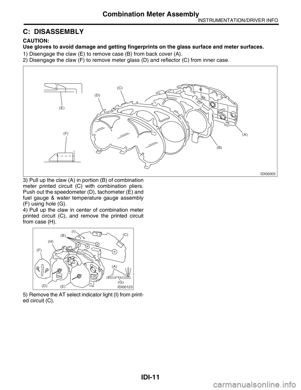
1) Disengage the claw (E) to remove case (B) from back cover (A).
2) Disengage the claw (F) to remove meter glass (D) and reflector (C) from inner case.
3) Pull up the claw (A) in portion (B) of combination
meter printed circuit (C) with combination pliers.
Push out the speedometer (D), tachometer (E) and
fuel gauge & water temperature gauge assembly
(F) using hole (G).
4) Pull up the claw in center of combination meter
printed circuit (C), and remove the printed circuit
from case (H).
5) Remove the AT select indicator light (I) from print-
ed circuit (C).
IDI00003
(A) (C)
(D)
(E)
(F)
(B)
IDI00123
(A)
(G)(C)
(B)
(H)
(F)
(D)
(E)
(I)
Page 396 of 2870

IDI-12
INSTRUMENTATION/DRIVER INFO
Combination Meter Assembly
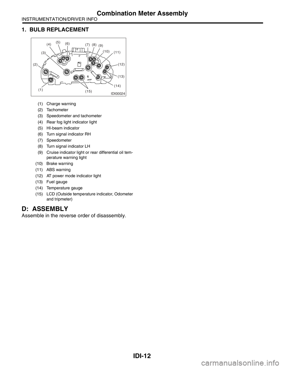
1. BULB REPLACEMENT
D: ASSEMBLY
Assemble in the reverse order of disassembly.
(1) Charge warning
(2) Tachometer
(3) Speedometer and tachometer
(4) Rear fog light indicator light
(5) HI-beam indicator
(6) Turn signal indicator RH
(7) Speedometer
(8) Turn signal indicator LH
(9) Cruise indicator light or rear differential oil tem-
perature warning light
(10) Brake warning
(11) ABS warning
(12) AT power mode indicator light
(13) Fuel gauge
(14) Temperature gauge
(15) LCD (Outside temperature indicator, Odometer
and tripmeter)
IDI00024(1) (2)(3)(5)
(6)
(7)(8)
(9)
(10)
(11)
(13)
(14)
(15)
(4)
(12)