2004 SUBARU FORESTER air suspension
[x] Cancel search: air suspensionPage 665 of 2870
FUJI HEAVY INDUSTRIES LTD. G8080GE6
2004 FORESTER SERVICE MANUAL QUICK REFERENCE INDEX
CHASSIS SECTION
This service manual has been prepared
to provide SUBARU service personnel
with the necessary information and data
for the correct maintenance and repair
of SUBARU vehicles.
This manual includes the procedures
for maintenance, disassembling, reas-
sembling, inspection and adjustment of
components and diagnostics for guid-
ance of experienced mechanics.
Please peruse and utilize this manual
fully to ensure complete repair work for
satisfying our customers by keeping
their vehicle in optimum condition.
When replacement of parts during
repair work is needed, be sure to use
SUBARU genuine parts.
All information, illustration and specifi-
cations contained in this manual are
based on the latest product information
available at the time of publication
approval.FRONT SUSPENSION FS
REAR SUSPENSION RS
WHEEL AND TIRE SYSTEM WT
DIFFERENTIAL DI
TRANSFER CASE TC
DRIVE SHAFT SYSTEM DS
ABS ABS
ABS (DIAGNOSTIC) ABS
BRAKE BR
PARKING BRAKE PB
POWER ASSISTED SYSTEM
(POWER STEERING)PS
Page 738 of 2870

PERIODIC MAINTENANCE SERVICE
PM
Page
1. General Description ....................................................................................2
2. Schedule .....................................................................................................3
3. Engine Oil....................................................................................................7
4. Engine Oil Filter...........................................................................................9
5. Spark Plugs ...............................................................................................10
6. V-belt .........................................................................................................11
7. Timing Belt ................................................................................................13
8. Fuel Line ...................................................................................................17
9. Fuel Filter ..................................................................................................18
10. Air Cleaner Element ..................................................................................19
11. Cooling System .........................................................................................20
12. Engine Coolant..........................................................................................21
13. Clutch System ...........................................................................................23
14. Transmission Gear Oil ..............................................................................24
15. Hill-holder System .....................................................................................25
16. ATF ...........................................................................................................26
17. Front & Rear Differential Oil ......................................................................28
18. Brake Line .................................................................................................30
19. Brake Fluid ................................................................................................32
20. Disc Brake Pads and Discs .......................................................................33
21. Brake Linings and Drums ..........................................................................34
22. Suspension ...............................................................................................36
23. Wheel Bearing...........................................................................................38
24. Axle Boots & Joints ...................................................................................39
25. Tire Rotation..............................................................................................40
26. Steering System (Power Steering) ............................................................41
Page 740 of 2870

PM-3
PERIODIC MAINTENANCE SERVICE
Schedule
2. Schedule
A: MAINTENANCE SCHEDULE 1
1. FOR EUROPE AREA
For periodic maintenance of over 120,000 km (75,000 miles) or 96 months, carry out inspection by referring
to the following table. For a maintenance period gone beyond these tables, apply them repeatedly as a set
of 120,000 km (75,000 miles) or 96 months.
Symbols used:
R: Replace
I: Inspection
(I): Recommended service for safe vehicle operation.
N
OTE:
(1) When the vehicle is used in extremely dusty conditions, the air cleaner element should be replaced more often.
(2) ATF filter is a maintenance free part. ATF filter needs replacement, when it is physically damaged or ATF leaked.Maintenance interval
[Number of months or km (miles), whichever occurs first]
Month 1224364860728496
Remarks ×1,000 km 1.6 5 15 30 45 60 75 90 105 120
×1,000 miles 1 3 9 19 28 38 47 56 66 75
1Engine oil RRRRRRRR
2Engine oil filter RRRRRRRR
3 Spark plug For Turbo R
Others RRRR
4Drive belt(s) IIIIIIII
5Camshaft drive belt RRRR
6Fuel line IIII
7 Fuel filter R R
8 Air cleaner element I R I R I R I R
9Cooling system IIII
10Coolant RRRR
11Clutch system IIII
12Hill-holder system IIII
13 Transmission oil I R I R
14 ATF I R I R
15 Front & rear differential I R I R
16Brake line IIII
17Brake fluid RRRR
18Disk brake pads & discs IIIIIIII
19Brake linings & drums IIII
20Parking brake IIII
21Suspension IIII
22 Wheel bearing(I)
23Axle boot & joint IIIIIIII
24Steering system IIII
Page 741 of 2870

PM-4
PERIODIC MAINTENANCE SERVICE
Schedule
2. EXCEPT FOR EUROPE AREA
For periodic maintenance of over 50,000 km (30,000 miles) or 48 months, carry out inspections by referring
to the following tables. For a maintenance period gone beyond these tables, apply them repeatedly as a set
of 50,000 km (30,000 miles) or 48 months.
For periodic maintenance of over 100,000 km (60,000 miles) or 48 months, carry out inspections by referring
to the following tables. For a maintenance period gone beyond these tables, apply them repeatedly as a set
of 100,000 km (60,000 miles) or 48 months.
Symbols used:
R: Replace
I: Inspection
(I): Recommended service for safe vehicle operation.
N
OTE:
(1) When the vehicle is used in extremely dusty conditions, the air cleaner element should be replaced more often.
(2) ATF filter is a maintenance free part. ATF filter needs replacement, when it is physically damaged or ATF leaked.Maintenance Interval
[Number of months or km (miles), whichever occurs first]
Months 12 24 36 48
Remarks ×1,000 km 5 12.5 25 37.5 50
×1,000 miles 3 7.5 15 22.5 30
1 Engine oil R R R R
2 Engine oil filter R R R R
Maintenance Interval
[Number of months or km (miles), whichever occurs first]
Months 12 24 36 48
Remarks ×1,000 km 1.6 25 50 75 100
×1,000 miles 1 15 30 45 60
3 Spark plugs For Turbo R
Others R R R R
4Drive belt(s) IIII
5 Camshaft drive belt R
6 Fuel line I I
7 Fuel filter R R
8 Air cleaner element I R I R
9 Cooling system I I
10 Coolant R R
11 Clutch system I I I I I
12 Hill-holder system I I I I I
13 Transmission oil R R
14 ATF R R
15 Front & rear differential oil R R
16 Brake line I I
17 Brake fluid R R
18 Disc brake pads & discs I I I I
19 Brake linings and drums I I
20 Parking brake I I I I
21 Suspension I I I I
22 Wheel bearing (I)
23 Axle boots & joints I I I I
24 Steering system (Power steering) I I I I
Page 774 of 2870

PM-37
PERIODIC MAINTENANCE SERVICE
Suspension
4. WHEEL ALIGNMENT OF FRONT SUS-
PENSION
1) Check the alignment of front suspension to en-
sure that following items conform to standard val-
ues.
Toe-in
Camber angle
Caster angle
Steering angle
2) When the caster angle does not conform to ref-
erence, visually inspect the following components
and replace deformed parts.
Suspension components [Strut assembly, cross-
member, transverse link, etc.]
Body parts to which suspensions are installed.
3) When the toe-in and camber are out of standard
value, adjust them so that they conform to respec-
tive service standard.
ment.>
4) When the right-and-left turning angles of tire are
out of standard, adjust to standard value.
Alignment.>
5. WHEEL ALIGNMENT OF REAR SUS-
PENSION
1) Check the alignment of rear suspension to en-
sure that following items are within standard val-
ues.
Toe-in
Camber angle
Thrust angle
2) When the camber angle does not conform to ref-
erence, visually inspect parts listed below. If defor-
mation is observed, replace the damaged parts.
Suspension components [Shock absorber, front
lateral links, rear lateral links, trailing link, etc.]
Body parts to which suspensions are installed.
3) When the toe-in and thrust angle are out of stan-
dard value, adjust them so that they conform to re-
spective service standard.
ment.>
6. OIL LEAKAGE OF STRUT
Visually inspect the front strut and rear strut for oil
leakage as instructed. If oil leakage reaches under
spring seat lower portion, replace the front strut and
rear strut.
7. TIGHTNESS OF BOLTS AND NUTS
Check the bolts and nuts shown in the figure for
looseness. Retighten the bolts and nuts to speci-
fied torque. If the self-lock nuts and bolts are re-
moved, replace them with new ones.
Front suspension:
Rear suspension:
8. DAMAGE TO SUSPENSION PARTS
Check the following parts and the fastening portion
of the vehicle body for deformation or excessive
rusting which impairs the suspension. Remove the
contaminations on spring seat lower portion with
care because dirt, sand, etc. tend to accumulate on
it. If necessary, replace the damaged parts with
new ones. If minor rust formation, pitting, etc. are
noted, remove the rust and apply remedial anti-cor-
rosion measures.
Front suspension
Transverse link
Crossmember
Strut
Rear suspension
Crossmember
Lateral links
Trailing link
Strut
In the district where salt is sprayed to melt snow
on a road in winter, check suspension parts for
damage caused by rust every 12 months after
lapse of 60 months. Take rust prevention measure
as required.
Page 835 of 2870
FU(H4SO)-53
FUEL INJECTION (FUEL SYSTEM)
Fuel Filler Pipe
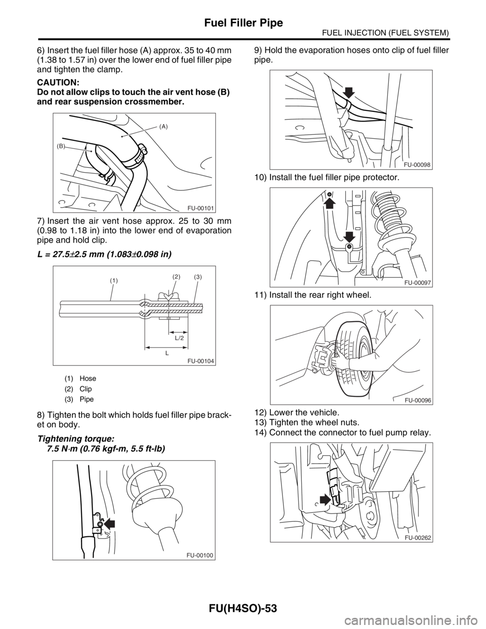
6) Insert the fuel filler hose (A) approx. 35 to 40 mm
(1.38 to 1.57 in) over the lower end of fuel filler pipe
and tighten the clamp.
CAUTION:
Do not allow clips to touch the air vent hose (B)
and rear suspension crossmember.
7) Insert the air vent hose approx. 25 to 30 mm
(0.98 to 1.18 in) into the lower end of evaporation
pipe and hold clip.
L = 27.5
±2.5 mm (1.083±0.098 in)
8) Tighten the bolt which holds fuel filler pipe brack-
et on body.
Tightening torque:
7.5 N
⋅m (0.76 kgf-m, 5.5 ft-lb)9) Hold the evaporation hoses onto clip of fuel filler
pipe.
10) Install the fuel filler pipe protector.
11) Install the rear right wheel.
12) Lower the vehicle.
13) Tighten the wheel nuts.
14) Connect the connector to fuel pump relay.
(1) Hose
(2) Clip
(3) Pipe
(A)
(B)
FU-00101
FU-00104
(1)(2)
L/2
L(3)
FU-00100
FU-00098
FU-00097
FU-00096
FU-00262
Page 1415 of 2870
FU(H4DOTC)-60
FUEL INJECTION (FUEL SYSTEM)
Fuel Filler Pipe
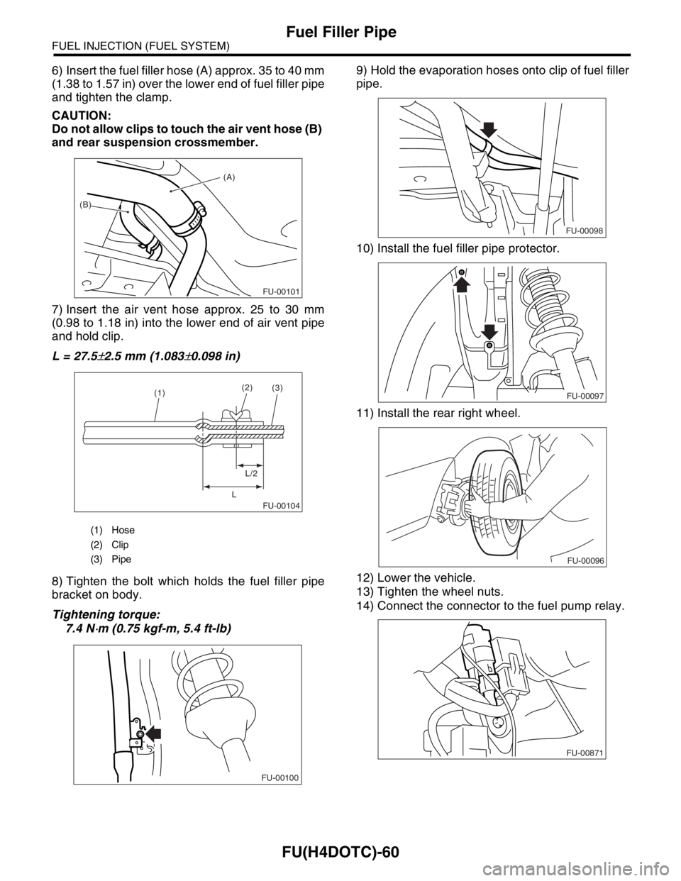
6) Insert the fuel filler hose (A) approx. 35 to 40 mm
(1.38 to 1.57 in) over the lower end of fuel filler pipe
and tighten the clamp.
CAUTION:
Do not allow clips to touch the air vent hose (B)
and rear suspension crossmember.
7) Insert the air vent hose approx. 25 to 30 mm
(0.98 to 1.18 in) into the lower end of air vent pipe
and hold clip.
L = 27.5
±2.5 mm (1.083±0.098 in)
8) Tighten the bolt which holds the fuel filler pipe
bracket on body.
Tightening torque:
7.4 N
⋅m (0.75 kgf-m, 5.4 ft-lb)9) Hold the evaporation hoses onto clip of fuel filler
pipe.
10) Install the fuel filler pipe protector.
11) Install the rear right wheel.
12) Lower the vehicle.
13) Tighten the wheel nuts.
14) Connect the connector to the fuel pump relay.
(1) Hose
(2) Clip
(3) Pipe
(A)
(B)
FU-00101
FU-00104
(1)(2)
L/2
L(3)
FU-00100
FU-00098
FU-00097
FU-00096
FU-00871
Page 1980 of 2870
FU(H4DOTC 2.5)-50
FUEL INJECTION (FUEL SYSTEM)
Fuel Filler Pipe
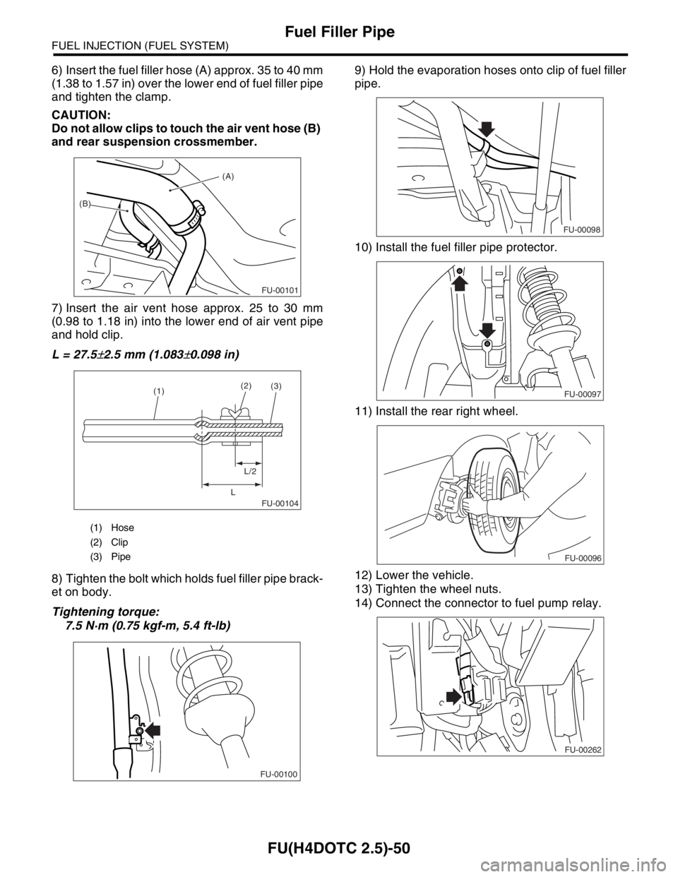
6) Insert the fuel filler hose (A) approx. 35 to 40 mm
(1.38 to 1.57 in) over the lower end of fuel filler pipe
and tighten the clamp.
CAUTION:
Do not allow clips to touch the air vent hose (B)
and rear suspension crossmember.
7) Insert the air vent hose approx. 25 to 30 mm
(0.98 to 1.18 in) into the lower end of air vent pipe
and hold clip.
L = 27.5
±2.5 mm (1.083±0.098 in)
8) Tighten the bolt which holds fuel filler pipe brack-
et on body.
Tightening torque:
7.5 N·m (0.75 kgf-m, 5.4 ft-lb)9) Hold the evaporation hoses onto clip of fuel filler
pipe.
10) Install the fuel filler pipe protector.
11) Install the rear right wheel.
12) Lower the vehicle.
13) Tighten the wheel nuts.
14) Connect the connector to fuel pump relay.
(1) Hose
(2) Clip
(3) Pipe
(A)
(B)
FU-00101
FU-00104
(1)(2)
L/2
L(3)
FU-00100
FU-00098
FU-00097
FU-00096
FU-00262