2004 SUBARU FORESTER engine ignition installation
[x] Cancel search: engine ignition installationPage 801 of 2870
FU(H4SO)-19
FUEL INJECTION (FUEL SYSTEM)
Intake Manifold
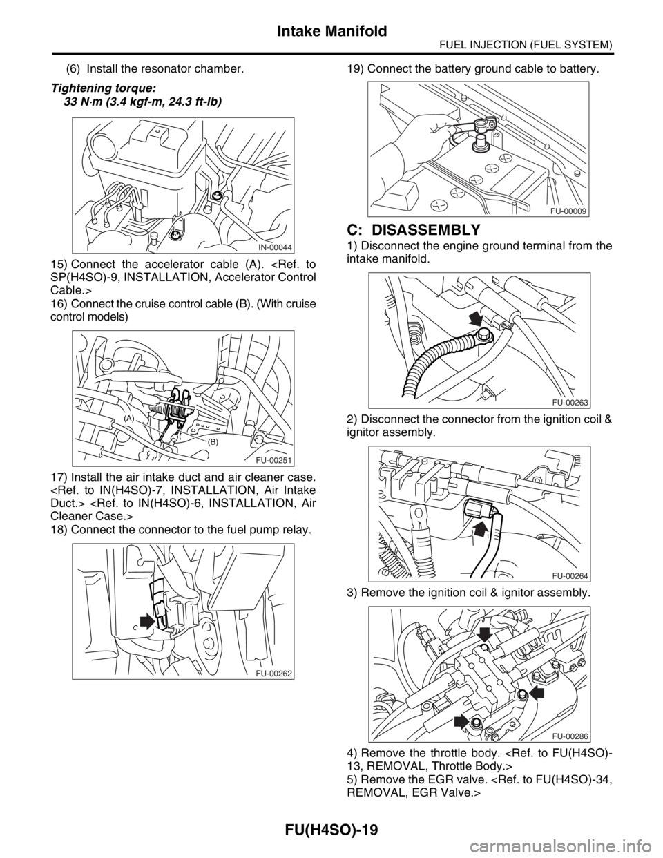
(6) Install the resonator chamber.
Tightening torque:
33 N
⋅m (3.4 kgf-m, 24.3 ft-lb)
15) Connect the accelerator cable (A).
Cable.>
16) Connect the cruise control cable (B). (With cruise
control models)
17) Install the air intake duct and air cleaner case.
18) Connect the connector to the fuel pump relay.19) Connect the battery ground cable to battery.
C: DISASSEMBLY
1) Disconnect the engine ground terminal from the
intake manifold.
2) Disconnect the connector from the ignition coil &
ignitor assembly.
3) Remove the ignition coil & ignitor assembly.
4) Remove the throttle body.
5) Remove the EGR valve.
FU-00251
(B)
(A)
FU-00262
FU-00009
FU-00263
FU-00264
FU-00286
Page 806 of 2870
FU(H4SO)-24
FUEL INJECTION (FUEL SYSTEM)
Intake Manifold
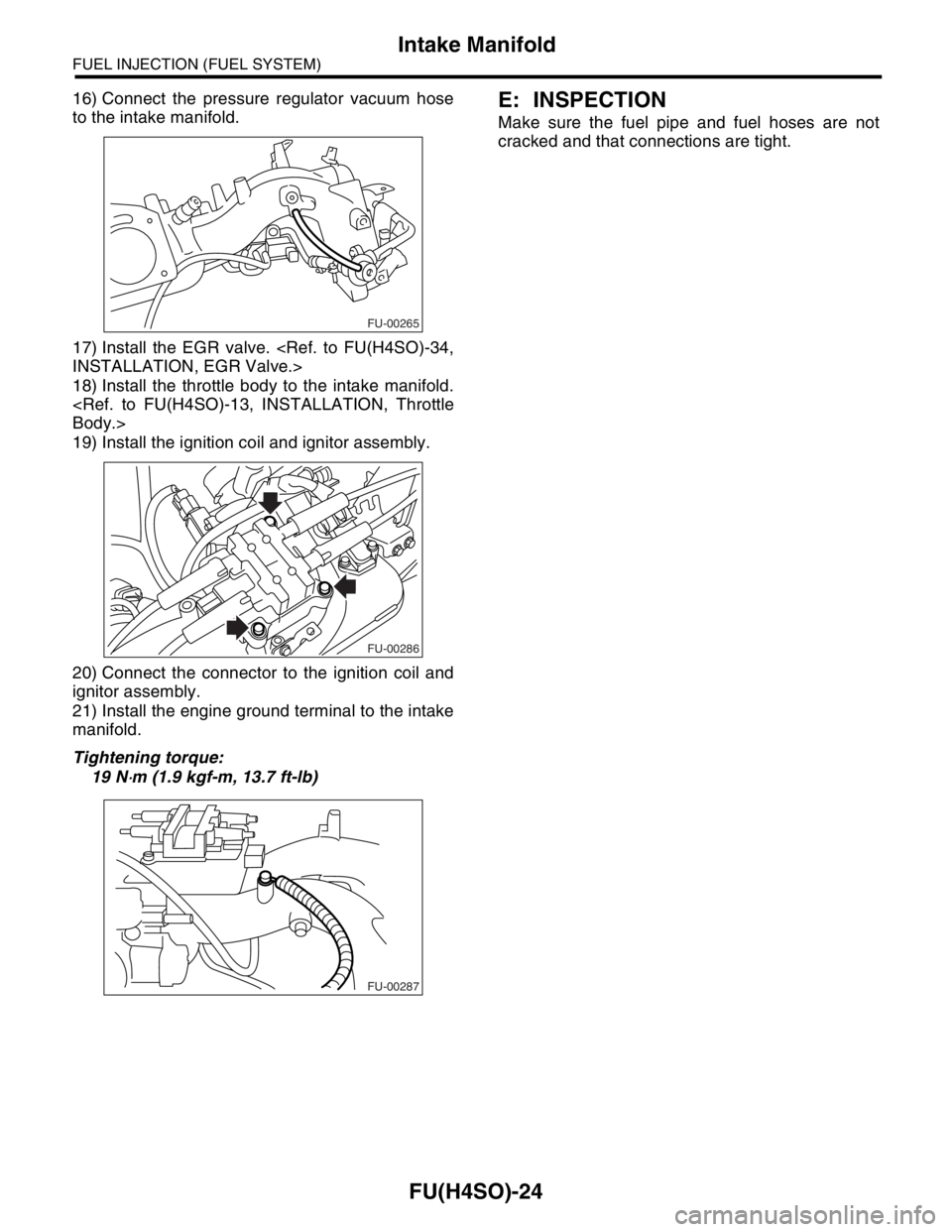
16) Connect the pressure regulator vacuum hose
to the intake manifold.
17) Install the EGR valve.
18) Install the throttle body to the intake manifold.
19) Install the ignition coil and ignitor assembly.
20) Connect the connector to the ignition coil and
ignitor assembly.
21) Install the engine ground terminal to the intake
manifold.
Tightening torque:
19 N
⋅m (1.9 kgf-m, 13.7 ft-lb)
E: INSPECTION
Make sure the fuel pipe and fuel hoses are not
cracked and that connections are tight.
FU-00265
FU-00286
FU-00287
Page 1242 of 2870

EN(H4SO)-144
ENGINE (DIAGNOSTIC)
Diagnostic Procedure with Diagnostic Trouble Code (DTC)
6 CHECK POWER SUPPLY LINE.
1) Turn the ignition switch to ON.
2) Measure the voltage between fuel injector
and engine ground on faulty cylinders.
Connector & terminal
#1 (E5) No. 2 (+) — Engine ground (
−):
#2 (E16) No. 2 (+) — Engine ground (
−):
#3 (E6) No. 2 (+) — Engine ground (
−):
#4 (E17) No. 2 (+) — Engine ground (
−):Is the voltage more than 10 V? Repair poor con-
tact in all connec-
tors in fuel injector
circuit.Repair harness
and connector.
N
OTE:
In this case repair
the following:
Open circuit in
harness between
main relay and fuel
injector connector
on faulty cylinders
Poor contact in
coupling connector
Poor contact in
main relay connec-
tor
Poor contact in
fuel injector con-
nector on faulty
cylinders
7 CHECK HARNESS BETWEEN FUEL INJEC-
TOR AND ECM CONNECTOR.
1) Turn the ignition switch to OFF.
2) Disconnect the connector from fuel injector
on faulty cylinder.
3) Turn the ignition switch to ON.
4) Measure the voltage between ECM con-
nector and chassis ground on faulty cylinders.
Connector & terminal
#1 (B134) No. 34 (+) — Chassis ground (
−):
#2 (B134) No. 23 (+) — Chassis ground (
−):
#3 (B134) No. 22 (+) — Chassis ground (
−):
#4 (B134) No. 8 (+) — Chassis ground (
−):Is the voltage more than 10 V? Repair battery
short circuit in har-
ness between
ECM and fuel
injector. After
repair, replace the
ECM.
Engine Control
Module (ECM).>Go to step 8.
8 CHECK FUEL INJECTOR.
1) Turn the ignition switch to OFF.
2) Measure the resistance between fuel injec-
tor terminals on faulty cylinder.
Te r m i n a l s
No. 1 — No. 2:Is the resistance less than 1
Ω?Replace the faulty
fuel injector
Fuel Injector.> and
ECM.
Engine Control
Module (ECM).>Go to step 9.
9 CHECK INSTALLATION OF CAMSHAFT PO-
SITION SENSOR/CRANKSHAFT POSITION
SENSOR.Is the installation of camshaft
position sensor or crankshaft
position sensor loosened?Tighten camshaft
position sensor or
crankshaft posi-
tion sensor.Go to step 10.
10 CHECK CRANK SPROCKET.
Remove the timing belt cover.Is the crank sprocket rusted or
does it have broken teeth?Replace the crank
sprocket.
Crank Sprocket.>Go to step 11.
11 CHECK INSTALLATION CONDITION OF
TIMING BELT.
Turn the crankshaft using ST, and align align-
ment mark on crank sprocket with alignment
mark on cylinder block.
ST 499987500 CRANKSHAFT SOCKETIs the timing belt dislocated
from its proper position?Repair installation
condition of timing
belt.
Timing Belt.>Go to step 12.
12 CHECK FUEL LEVEL.Is the fuel meter indication
higher than the “Lower” level?Go to step 13.Replenish fuel so
fuel meter indica-
tion is higher than
the “Lower” level.
After replenishing
fuel, Go to step 13. Step Check Yes No
Page 1247 of 2870

EN(H4SO)-149
ENGINE (DIAGNOSTIC)
Diagnostic Procedure with Diagnostic Trouble Code (DTC)
Step Check Yes No
1 CHECK HARNESS BETWEEN KNOCK SEN-
SOR AND ECM CONNECTOR.
1) Turn the ignition switch to OFF.
2) Disconnect the connector from ECM.
3) Measure the resistance between ECM har-
ness connector and chassis ground.
Connector & terminal
(B135) No. 16 — Chassis ground:Is the resistance more than
700 kΩ?Go to step 2.Repair harness
and connector.
N
OTE:
In this case repair
the following:
Open circuit in
harness between
knock sensor and
ECM connector
Poor contact in
knock sensor con-
nector
Poor contact in
coupling connector
2 CHECK KNOCK SENSOR.
1) Disconnect the connector from knock sen-
sor.
2) Measure the resistance between knock
sensor connector terminal and engine ground.
Te r m i n a l
No. 2 — Engine ground:Is the resistance more than
700 kΩ?Go to step 3.Repair harness
and connector.
NOTE:
In this case repair
the following:
Poor contact in
knock sensor con-
nector
3 CHECK CONDITION OF KNOCK SENSOR
INSTALLATION.Is the knock sensor installation
bolt tightened securely?Replace the knock
sensor.
Knock Sensor.>Tighten knock sen-
sor installation bolt
securely.
Page 1251 of 2870

EN(H4SO)-153
ENGINE (DIAGNOSTIC)
Diagnostic Procedure with Diagnostic Trouble Code (DTC)
Step Check Yes No
1 CHECK HARNESS BETWEEN CRANK-
SHAFT POSITION SENSOR AND ECM CON-
NECTOR.
1) Turn the ignition switch to OFF.
2) Disconnect the connector from the crank-
shaft position sensor.
3) Measure the resistance of harness
between crankshaft position sensor connector
and engine ground.
Connector & terminal
(E10) No. 1 — Engine ground:Is the resistance more than
100 kΩ?Repair harness
and connector.
N
OTE:
In this case repair
the following:
Open circuit in
harness between
crankshaft posi-
tion sensor and
ECM connector
Poor contact in
ECM connector.
Poor contact in
coupling connectorGo to step 2.
2 CHECK HARNESS BETWEEN CRANK-
SHAFT POSITION SENSOR AND ECM CON-
NECTOR.
Measure the resistance of harness between
crankshaft position sensor connector and
engine ground.
Connector & terminal
(E10) No. 1 — Engine ground:Is the resistance less than 10
Ω?Repair ground
short circuit in har-
ness between
crankshaft posi-
tion sensor and
ECM connector.
N
OTE:
The harness be-
tween both connec-
tors are shielded.
Repair ground short
circuit in harness to-
gether with shield.Go to step 3.
3 CHECK HARNESS BETWEEN CRANK-
SHAFT POSITION SENSOR AND ECM CON-
NECTOR.
Measure the resistance of harness between
crankshaft position sensor connector and
engine ground.
Connector & terminal
(E10) No. 2 — Engine ground:Is the resistance less than 5
Ω?Go to step 4.Repair harness
and connector.
NOTE:
In this case repair
the following:
Open circuit in
harness between
crankshaft posi-
tion sensor and
ECM connector
Poor contact in
ECM connector.
Poor contact in
coupling connector
4 CHECK CONDITION OF CRANKSHAFT PO-
SITION SENSOR.Is the crankshaft position sen-
sor installation bolt tightened
securely?Go to step 5.Tighten the crank-
shaft position sen-
sor installation bolt
securely.
5 CHECK CRANKSHAFT POSITION SENSOR.
1) Remove the crankshaft position sensor.
2) Measure the resistance between connector
terminals of crankshaft position sensor.
Te r m i n a l s
No. 1 — No. 2:Is the resistance 1 — 4 kΩ? Repair poor con-
tact in crankshaft
position sensor
connector.Replace the crank-
shaft position sen-
sor.
Crankshaft Posi-
tion Sensor.>
Page 1253 of 2870

EN(H4SO)-155
ENGINE (DIAGNOSTIC)
Diagnostic Procedure with Diagnostic Trouble Code (DTC)
Step Check Yes No
1 CHECK ANY OTHER DTC ON DISPLAY.Is any other DTC displayed? Inspect the DTC
using “List of Diag-
nostic Trouble
Code (DTC)”.
of Diagnostic Trou-
ble Code (DTC).>Go to step 2.
2 CHECK CONDITION OF CRANKSHAFT PO-
SITION SENSOR.
Turn the ignition switch to OFF.Is the crankshaft position sen-
sor installation bolt tightened
securely?Go to step 3.Tighten the crank-
shaft position sen-
sor installation bolt
securely.
3 CHECK CRANK SPROCKET.
Remove the front belt cover.Are crank sprocket teeth
cracked or damaged?Replace the crank
sprocket.
Crank Sprocket.>Go to step 4.
4 CHECK INSTALLATION CONDITION OF
TIMING BELT.
Turn the crankshaft using ST, and align align-
ment mark on crank sprocket with alignment
mark on cylinder block.
ST 499987500 CRANKSHAFT SOCKETIs the timing belt dislocated
from its proper position?Repair installation
condition of timing
belt.
Timing Belt.>Replace the crank-
shaft position sen-
sor.
Crankshaft Posi-
tion Sensor.>
Page 1255 of 2870

EN(H4SO)-157
ENGINE (DIAGNOSTIC)
Diagnostic Procedure with Diagnostic Trouble Code (DTC)
Step Check Yes No
1 CHECK HARNESS BETWEEN CAMSHAFT
POSITION SENSOR AND ECM CONNEC-
TOR.
1) Turn the ignition switch to OFF.
2) Disconnect the connector from camshaft
position sensor.
3) Measure the resistance of harness
between camshaft position sensor connector
and engine ground.
Connector & terminal
(E15) No. 1 — Engine ground:Is the resistance more than
100 kΩ?Repair harness
and connector.
N
OTE:
In this case repair
the following:
Open circuit in
harness between
camshaft position
sensor and ECM
connector
Poor contact in
ECM connector.
Poor contact in
coupling connectorGo to step 2.
2 CHECK HARNESS BETWEEN CAMSHAFT
POSITION SENSOR AND ECM CONNEC-
TOR.
Measure the resistance of harness between
camshaft position sensor connector and
engine ground.
Connector & terminal
(E15) No. 1 — Engine ground:Is the resistance less than 10
Ω?Repair ground
short circuit in har-
ness between
camshaft position
sensor and ECM
connector.
N
OTE:
The harness be-
tween both connec-
tors are shielded.
Repair ground short
circuit in harness to-
gether with shield.Go to step 3.
3 CHECK HARNESS BETWEEN CAMSHAFT
POSITION SENSOR AND ECM CONNEC-
TOR.
Measure the resistance of harness between
camshaft position sensor connector and
engine ground.
Connector & terminal
(E15) No. 2 — Engine ground:Is the resistance less than 5
Ω?Go to step 4.Repair harness
and connector.
NOTE:
In this case repair
the following:
Open circuit in
harness between
camshaft position
sensor and ECM
connector
Poor contact in
ECM connector.
Poor contact in
coupling connector
4 CHECK CONDITION OF CAMSHAFT POSI-
TION SENSOR.Is the camshaft position sensor
installation bolt tightened
securely?Go to step 5.Tighten the cam-
shaft position sen-
sor installation bolt
securely.
5 CHECK CAMSHAFT POSITION SENSOR.
1) Remove the camshaft position sensor.
2) Measure the resistance between connector
terminals of camshaft position sensor.
Te r m i n a l s
No. 1 — No. 2:Is the resistance 1 — 4 kΩ? Repair poor con-
tact in camshaft
position sensor
connector.Replace the cam-
shaft position sen-
sor.
Camshaft Position
Sensor.>
Page 1257 of 2870

EN(H4SO)-159
ENGINE (DIAGNOSTIC)
Diagnostic Procedure with Diagnostic Trouble Code (DTC)
Step Check Yes No
1 CHECK ANY OTHER DTC ON DISPLAY.Is any other DTC displayed? Inspect the DTC
using “List of Diag-
nostic Trouble
Code (DTC)”.
of Diagnostic Trou-
ble Code (DTC).>Go to step 2.
2 CHECK HARNESS BETWEEN CAMSHAFT
POSITION SENSOR AND ECM CONNEC-
TOR.
1) Turn the ignition switch to OFF.
2) Disconnect the connector from camshaft
position sensor.
3) Measure the resistance of harness
between camshaft position sensor connector
and engine ground.
Connector & terminal
(E15) No. 1 — Engine ground:Is the resistance more than
100 kΩ?Repair harness
and connector.
N
OTE:
In this case repair
the following:
Open circuit in
harness between
camshaft position
sensor and ECM
connector
Poor contact in
ECM connector.
Poor contact in
coupling connectorGo to step 3.
3 CHECK HARNESS BETWEEN CAMSHAFT
POSITION SENSOR AND ECM CONNEC-
TOR.
Measure the resistance of harness between
camshaft position sensor connector and
engine ground.
Connector & terminal
(E15) No. 1 — Engine ground:Is the resistance less than 10
Ω?Repair ground
short circuit in har-
ness between
camshaft position
sensor and ECM
connector.
N
OTE:
The harness be-
tween both con-
nectors are
shielded. Repair
ground short circuit
in harness togeth-
er with shield.Go to step 4.
4 CHECK HARNESS BETWEEN CAMSHAFT
POSITION SENSOR AND ECM CONNEC-
TOR.
Measure the resistance of harness between
camshaft position sensor connector and
engine ground.
Connector & terminal
(E15) No. 2 — Engine ground:Is the resistance less than 5
Ω?Go to step 5.Repair harness
and connector.
N
OTE:
In this case repair
the following:
Open circuit in
harness between
camshaft position
sensor and ECM
connector
Poor contact in
ECM connector.
Poor contact in
coupling connector
5 CHECK CONDITION OF CAMSHAFT POSI-
TION SENSOR.Is the camshaft position sensor
installation bolt tightened
securely?Go to step 6.Tighten the cam-
shaft position sen-
sor installation bolt
securely.
6 CHECK CAMSHAFT POSITION SENSOR.
1) Remove the camshaft position sensor.
2) Measure the resistance between connector
terminals of camshaft position sensor.
Te r m i n a l
No. 1 — No. 2:Is the resistance 1 — 4 kΩ? Go to step 7.Replace the cam-
shaft position sen-
sor.
Camshaft Position
Sensor.>