2004 SUBARU FORESTER ground clearance
[x] Cancel search: ground clearancePage 38 of 2870
AC-36
HVAC SYSTEM (HEATER, VENTILATOR AND A/C)
Compressor
11.Compressor
A: INSPECTION
1. MAGNETIC CLUTCH CLEARANCE
1) Check the clearance of the entire circumference
around the drive plate and pulley.
Standard:
0.3 — 0.6 mm (0.0118 — 0.0236 in)
2. MAGNETIC CLUTCH OPERATION
1) Disconnect the compressor connector.
2) Connect the battery positive (+) terminal to the
No. 3 terminal of the compressor connector.
3) Make sure the magnet clutch engages.
If NG, replace the compressor.
B: REMOVAL
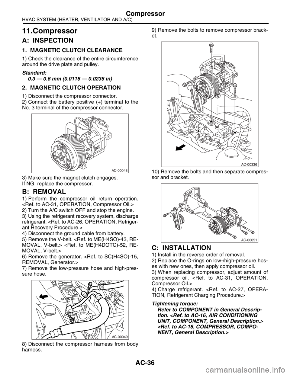
1) Perform the compressor oil return operation.
2) Turn the A/C switch OFF and stop the engine.
3) Using the refrigerant recovery system, discharge
refrigerant.
4) Disconnect the ground cable from battery.
5) Remove the V-belt.
6) Remove the generator.
7) Remove the low-pressure hose and high-pres-
sure hose.
8) Disconnect the compressor harness from body
harness.9) Remove the bolts to remove compressor brack-
et.
10) Remove the bolts and then separate compres-
sor and bracket.
C: INSTALLATION
1) Install in the reverse order of removal.
2) Replace the O-rings on low-/high-pressure hos-
es with new ones, then apply compressor oil.
3) When replacing compressor, adjust amount of
compressor oil.
4) Charge refrigerant.
Tightening torque:
Refer to COMPONENT in General Descrip-
tion.
AC-00048
AC-00049
AC-00336
AC-00051
Page 243 of 2870

SB-9
SEAT BELT SYSTEM
Seat Belt Warning System
14 CHECK HARNESS BETWEEN TCU AND
SEAT BELT TIMER MODULE.
Measure the resistance between seat belt
timer module harness connector and chassis
ground.
Connector & terminal
(B44) No. 7 — Chassis ground:Is the resistance less than 10
Ω?Go to step 15.Repair the short of
harness.
15 CHECK SEAT BELT TIMER MODULE OUT-
PUT SIGNAL.
1) Turn the ignition switch to ON.
2) Measure the voltage between seat belt
timer module harness connector and chassis
ground.
Connector & terminal
(B44) No. 2 (+) — Chassis ground (–):Is the voltage more than 10 V? Go to step 16.Check the wiring
harness and com-
bination meter,
and then repair or
replace them.
16 CHECK POOR CONTACT.
Check the poor contact of seat belt warning
light circuit.Is there any poor contact
occurs?Repair the poor
contact.Go to step 17.
17 CHECK SEAT BELT TIMER MODULE.
1) Connect all connectors.
2) Lift-up the vehicle and place rigid racks.
NOTE:
Raise all wheels off floor.
3) Hold the tang plate disconnected from seat
belt buckle.
4) Start the engine, and set the vehicle speed
less than 19 km/h (12 MPH)
N
OTE:
The speed difference between front and rear
wheels may light the ABS warning light, but this
indicates no malfunction. When diagnosis is fin-
ished, perform the ABS memory clearance pro-
cedure of OBD system.
Check seat belt warning light comes on.Does the seat belt warning
light come on?Go to step 18.Replace the seat
belt timer module.
18 CHECK SEAT BELT TIMER MODULE.
1) Connect all connectors.
2) Lift-up the vehicle and place rigid racks.
N
OTE:
Raise all wheels off floor.
3) Hold the tang plate disconnected from seat
belt buckle.
4) Start the engine, and set the vehicle speed
more than 25 km/h (16 MPH).
NOTE:
The speed difference between front and rear
wheels may light the ABS warning light, but this
indicates no malfunction. When diagnosis is fin-
ished, perform the ABS memory clearance pro-
cedure of OBD system.
Check seat belt warning light comes on and
buzzer beeps.Does the seat belt warning
light come on and buzzer
beep?Temporary poor
contact of connec-
tor or harness may
be the cause.
Check the poor
contact.Replace the seat
belt timer module. Step Check Yes No
Page 256 of 2870

LI-2
LIGHTING SYSTEM
General Description
1. General Description
A: SPECIFICATION
B: PRECAUTIONS
Before removing and installing parts, always disconnect the battery ground cable. When replacing audio,
control module, and other parts provided with memory functions, record memory contents before disconnect-
ing the battery ground cable. Otherwise, the memory will be erased.
Reassemble in reverse order of disassembly, unless otherwise indicated.
Adjust parts to the given specifications.
Connect the connectors and hoses securely during reassembly.
After reassembly, make sure functional parts operate smoothly.
WARNING:
Airbag system wiring harness is routed near electrical parts and switches. All airbag system wiring
harnesses and connectors are yellow. Do not use electric test equipment on these circuits.
Be careful not to damage the airbag system wiring harness when servicing electrical parts and
switches.
C: PREPARATION TOOL
1. GENERAL TOOL
Headlight12 V — 55 W/60 W
Front turn signal light 12 V — 21 W
Clearance light12 V — 5 W
Side marker light12 V — 5 W
Front fog light12 V — 55 W
Rear combination lightTail/Stop light 12 V — 5/21 W
Turn signal light 12 V — 21 W
Back-up light 12 V — 16 W
License plate light12 V — 5 W
High-mounted stop lightStandard type 12 V — 13 W
Rear spoiler built-in type 12 V — 1.2 W
Room light12 V — 8 W
Spot light12 V — 8 W
Luggage room light12 V — 5 W
TOOL NAME REMARKS
Circuit tester Used for measuring resistance and voltage.
Page 257 of 2870
LI-3
LIGHTING SYSTEM
Headlight and Tail Light System
2. Headlight and Tail Light Sys-
tem
A: WIRING DIAGRAM
1. HEADLIGHT
2. CLEARANCE LIGHT AND ILLUMINA-
TION LIGHT
B: INSPECTION
1. HEADLIGHT SWITCH
2. HEADLIGHT RELAY
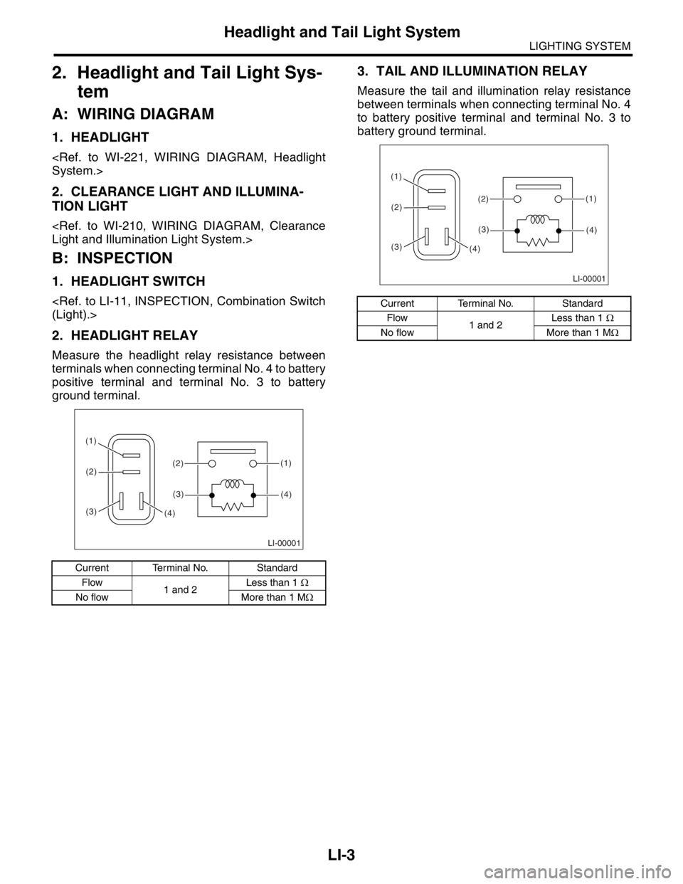
Measure the headlight relay resistance between
terminals when connecting terminal No. 4 to battery
positive terminal and terminal No. 3 to battery
ground terminal.
3. TAIL AND ILLUMINATION RELAY
Measure the tail and illumination relay resistance
between terminals when connecting terminal No. 4
to battery positive terminal and terminal No. 3 to
battery ground terminal.
Current Terminal No. Standard
Flow
1 and 2Less than 1 Ω
No flow More than 1 MΩ
LI-00001
(1)
(2) (1)
(4)(2)
(3)
(3)(4)
Current Terminal No. Standard
Flow
1 and 2Less than 1 Ω
No flow More than 1 MΩ
LI-00001
(1)
(2) (1)
(4)(2)
(3)
(3)(4)
Page 468 of 2870

SR-4
SUNROOF/T-TOP/CONVERTIBLE TOP (SUNROOF)
Sunroof Control System
2. Sunroof Control System
A: WIRING DIAGRAM
1. SUNROOF
B: INSPECTION
Symptom Checking order
Water leaks. (1) Check roof panel and sunroof lid for improper or poor sealing.
(2) Check drain tube for clogging.
(3) Check sunroof frame seal and body for improper fit.
Booming noise (1) Check sunroof lid and roof panel for improper clearance.
(2) Check sunshade and roof trim for improper clearance.
Abnormal motor noise (1) Check motor for looseness.
(2) Check gears and bearings for wear.
(3) Check cables for wear.
(4) Check cable pipe for deformities.
Failure of sunroof
(Motor operates properly.)(1) Check guide rail for foreign particles.
(2) Check guide rail for improper installation.
(3) Check parts for mutual interference.
(4) Check cable slider for improper clinching.
(5) Check cable for improper installation.
(6) Check clutch adjusting nut for improper tightness.
Motor does not rotate or rotates improperly. (1) Check fuse for blow-out.
(2) Check switch for improper function.
(3) Check motor for incorrect terminal voltage.
(4) Check relay for improper operation.
(5) Check poor grounding system.
(6) Check harness for open or short and terminals for poor connections.
(7) Check limit switch for improper operation.
Page 900 of 2870
ME(H4SO)-31
MECHANICAL
Valve Clearance
8. Valve Clearance
A: INSPECTION
NOTE:
Inspection and adjustment of the valve clearance
should be performed while engine is cold.
1) Set the vehicle on a lift.
2) Lift-up the vehicle.
3) Remove the under cover.
4) Lower the vehicle.
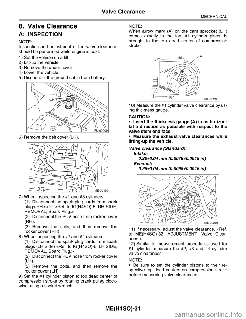
5) Disconnect the ground cable from battery.
6) Remove the belt cover (LH).
7) When inspecting the #1 and #3 cylinders:
(1) Disconnect the spark plug cords from spark
plugs RH side.
(2) Disconnect the PCV hose from rocker cover
(RH).
(3) Remove the bolts, and then remove the
rocker cover (RH).
8) When inspecting the #2 and #4 cylinders:
(1) Disconnect the spark plug cords from spark
plugs (LH Side)
(2) Disconnect the PCV hose from rocker cover
(LH).
(3) Remove the bolts, and then remove the
rocker cover (LH).
9) Set the #1 cylinder piston to top dead center of
compression stroke by rotating crank pulley clock-
wise using a socket wrench.NOTE:
When arrow mark (A) on the cam sprocket (LH)
comes exactly to the top, #1 cylinder piston is
brought to the top dead center of compression
stroke.
10) Measure the #1 cylinder valve clearance by us-
ing thickness gauge.
CAUTION:
Insert the thickness gauge (A) in as horizon-
tal a direction as possible with respect to the
valve stem end face.
Measure the exhaust valve clearances while
lifting-up the vehicle.
Valve clearance (Standard):
Intake;
0.20
±0.04 mm (0.0079±0.0016 in)
Exhaust;
0.25
±0.04 mm (0.0098±0.0016 in)
11) If necessary, adjust the valve clearance.
ance.>
12) Similar to measurement procedures used for
#1 cylinder, measure the #2, #3 and #4 cylinder
valve clearances.
NOTE:
Be sure to set the cylinder pistons to their re-
spective top dead centers on compression stroke
before measuring valve clearances.
FU-00009
ME-00199
ME-00200
(A)
ME-00201
(A)
Page 1105 of 2870
EN(H4SO)-7
ENGINE (DIAGNOSTIC)
General Description
The antenna feeder must be placed as far
apart as possible from the ECM and MFI har-
ness.
Carefully adjust the antenna for correct
matching.
When mounting a large power type radio, pay
special attention to the three items above men-
tioned.
Incorrect installation of the radio may affect
the operation of the ECM.
13) Before disconnecting the fuel hose, disconnect
the fuel pump connector and crank the engine for
more than five seconds to release pressure in the
fuel system. If engine starts during this operation,
run it until it stops.
14) Problems in the electronic-controlled automatic
transmission may be caused by failure of the en-
gine, the electronic control system, the transmis-
sion proper, or by a combination of these. These
three causes must be distinguished clearly when
performing diagnostics.
15) Diagnostics should be conducted by rotating
with simple, easy operations and proceeding to
complicated, difficult operations. The most impor-
tant thing in diagnostics is to understand the cus-
tomer’s complaint, and distinguish between the
three causes.
16) In AT models, do not continue the stall for more
than five seconds. (from closed throttle, fully open
throttle to stall engine speed.)
17) On the model with ABS, when performing driv-
ing test in jacked-up or lifted-up position, some-
times the warning light may be lit, but this is not a
malfunction of the system. The reason for this is the
speed difference between the front and rear
wheels. After diagnosis of engine control system,
perform the ABS memory clearance procedure of
self-diagnosis function.
B: INSPECTION
Before performing diagnostics, check the following
items which might affect engine problems:
1. BATTERY
1) Measure battery voltage and specific gravity of
electrolyte.
Standard voltage: 12 V
Specific gravity: Above 1.260
2) Check the condition of the main and other fuses,
and harnesses and connectors. Also check for
proper grounding.
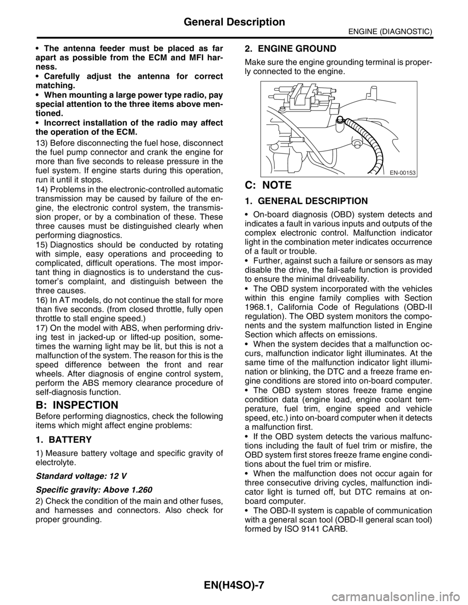
2. ENGINE GROUND
Make sure the engine grounding terminal is proper-
ly connected to the engine.
C: NOTE
1. GENERAL DESCRIPTION
On-board diagnosis (OBD) system detects and
indicates a fault in various inputs and outputs of the
complex electronic control. Malfunction indicator
light in the combination meter indicates occurrence
of a fault or trouble.
Further, against such a failure or sensors as may
disable the drive, the fail-safe function is provided
to ensure the minimal driveability.
The OBD system incorporated with the vehicles
within this engine family complies with Section
1968.1, California Code of Regulations (OBD-II
regulation). The OBD system monitors the compo-
nents and the system malfunction listed in Engine
Section which affects on emissions.
When the system decides that a malfunction oc-
curs, malfunction indicator light illuminates. At the
same time of the malfunction indicator light illumi-
nation or blinking, the DTC and a freeze frame en-
gine conditions are stored into on-board computer.
The OBD system stores freeze frame engine
condition data (engine load, engine coolant tem-
perature, fuel trim, engine speed and vehicle
speed, etc.) into on-board computer when it detects
a malfunction first.
If the OBD system detects the various malfunc-
tions including the fault of fuel trim or misfire, the
OBD system first stores freeze frame engine condi-
tions about the fuel trim or misfire.
When the malfunction does not occur again for
three consecutive driving cycles, malfunction indi-
cator light is turned off, but DTC remains at on-
board computer.
The OBD-II system is capable of communication
with a general scan tool (OBD-II general scan tool)
formed by ISO 9141 CARB.
EN-00153
Page 1493 of 2870
ME(H4DOTC)-37
MECHANICAL
Valve Clearance
8. Valve Clearance
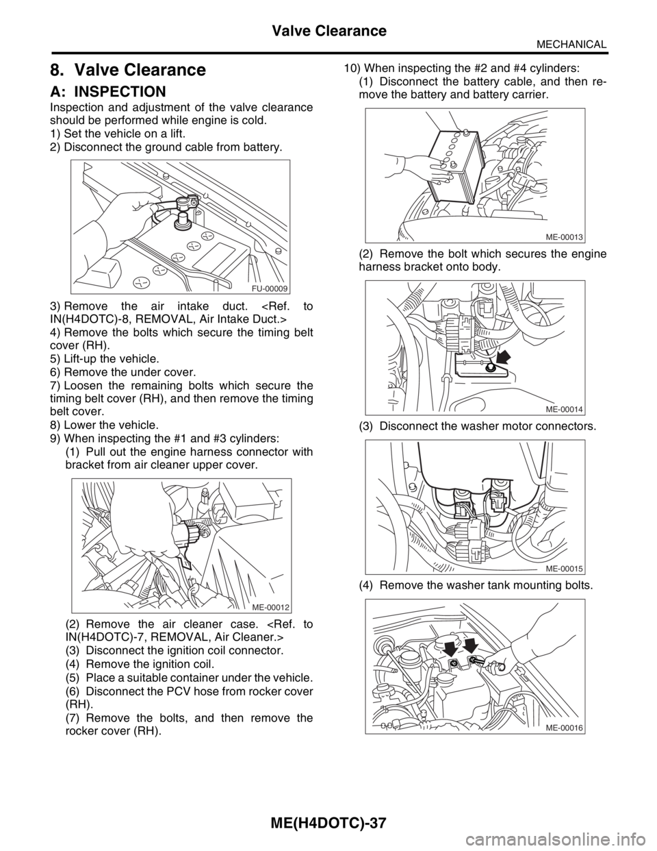
A: INSPECTION
Inspection and adjustment of the valve clearance
should be performed while engine is cold.
1) Set the vehicle on a lift.
2) Disconnect the ground cable from battery.
3) Remove the air intake duct.
4) Remove the bolts which secure the timing belt
cover (RH).
5) Lift-up the vehicle.
6) Remove the under cover.
7) Loosen the remaining bolts which secure the
timing belt cover (RH), and then remove the timing
belt cover.
8) Lower the vehicle.
9) When inspecting the #1 and #3 cylinders:
(1) Pull out the engine harness connector with
bracket from air cleaner upper cover.
(2) Remove the air cleaner case.
(3) Disconnect the ignition coil connector.
(4) Remove the ignition coil.
(5) Place a suitable container under the vehicle.
(6) Disconnect the PCV hose from rocker cover
(RH).
(7) Remove the bolts, and then remove the
rocker cover (RH).10) When inspecting the #2 and #4 cylinders:
(1) Disconnect the battery cable, and then re-
move the battery and battery carrier.
(2) Remove the bolt which secures the engine
harness bracket onto body.
(3) Disconnect the washer motor connectors.
(4) Remove the washer tank mounting bolts.
FU-00009
ME-00012
ME-00013
ME-00014
ME-00015
ME-00016