Page 268 of 2870

LI-14
LIGHTING SYSTEM
Headlight Assembly
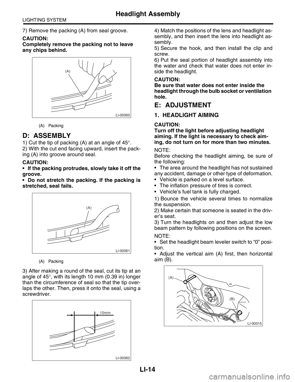
7) Remove the packing (A) from seal groove.
CAUTION:
Completely remove the packing not to leave
any chips behind.
D: ASSEMBLY
1) Cut the tip of packing (A) at an angle of 45°.
2) With the cut end facing upward, insert the pack-
ing (A) into groove around seal.
CAUTION:
If the packing protrudes, slowly take it off the
groove.
Do not stretch the packing. If the packing is
stretched, seal fails.
3) After making a round of the seal, cut its tip at an
angle of 45°, with its length 10 mm (0.39 in) longer
than the circumference of seal so that the tip over-
laps the other. Then, press it onto the seal, using a
screwdriver.4) Match the positions of the lens and headlight as-
sembly, and then insert the lens into headlight as-
sembly.
5) Secure the hook, and then install the clip and
screw.
6) Put the seal portion of headlight assembly into
the water and check that water does not enter in-
side the headlight.
CAUTION:
Be sure that water does not enter inside the
headlight through the bulb socket or ventilation
hole.
E: ADJUSTMENT
1. HEADLIGHT AIMING
CAUTION:
Turn off the light before adjusting headlight
aiming. If the light is necessary to check aim-
ing, do not turn on for more than two minutes.
NOTE:
Before checking the headlight aiming, be sure of
the following:
The area around the headlight has not sustained
any accident, damage or other type of deformation.
Vehicle is parked on a level surface.
The inflation pressure of tires is correct.
Vehicle’s fuel tank is fully charged.
1) Bounce the vehicle several times to normalize
the suspension.
2) Make certain that someone is seated in the driv-
er’s seat.
3) Turn the headlights on and then adjust the low
beam pattern by following positions on the screen.
NOTE:
Set the headlight beam leveler switch to “0” posi-
tion.
Adjust the vertical aim (A) first, then horizontal
aim (B).(A) Packing
(A) Packing
LI-00060
(A)
LI-00061
(A)
LI-00062
10mm
LI-00015
(A)
(B)
Page 711 of 2870
ID-2
IDENTIFICATION
Identification
1. Identification
A: IDENTIFICATION
1. IDENTIFICATION NUMBER AND LABEL LOCATIONS
The VIN (Vehicle Identification Numbers) is used to classify the vehicle.
Positioning of the plate label for identification
ID-00015
Vehicle identification
number
Model number plate Emission control labelVacuum hose
piping label
ID plate (Europe model)
ADR compliance plate
(Australia model)Tire inflation pressure label
(Driver side) (Australia model)
Tire pressure label
(Driver side) (Except Australia model)
Saudi Arabia plate
(Saudi Arabia model)
Built date plate
(Australia model)
ID-00011Engine serial number
ENGINE
ID-00012
4ATTransmission serial number
ID-00013
Transmission serial number5MT
Page 728 of 2870

PI-5
PRE-DELIVERY INSPECTION
Pre-delivery Inspection
1. APPEARANCE CHECK
1) If the vehicle is covered with protective coating,
visually check the vehicle body for damage and
dents.
2) If there is no protective coating, check the body
paints for small areas of damage or stains and re-
pair as necessary.
3) Check the window glass, door glass, and lights
for any cracks or damage and repair or replace the
parts as necessary.
4) Check the plated parts, such as the grilles and
door knobs, for damage or loss of gloss and repair
or replace the parts as necessary.
2. TIRE CHECK
Check the tire outer faces for any damage.
Check the tire air pressure by referring to the fol-
lowing table.
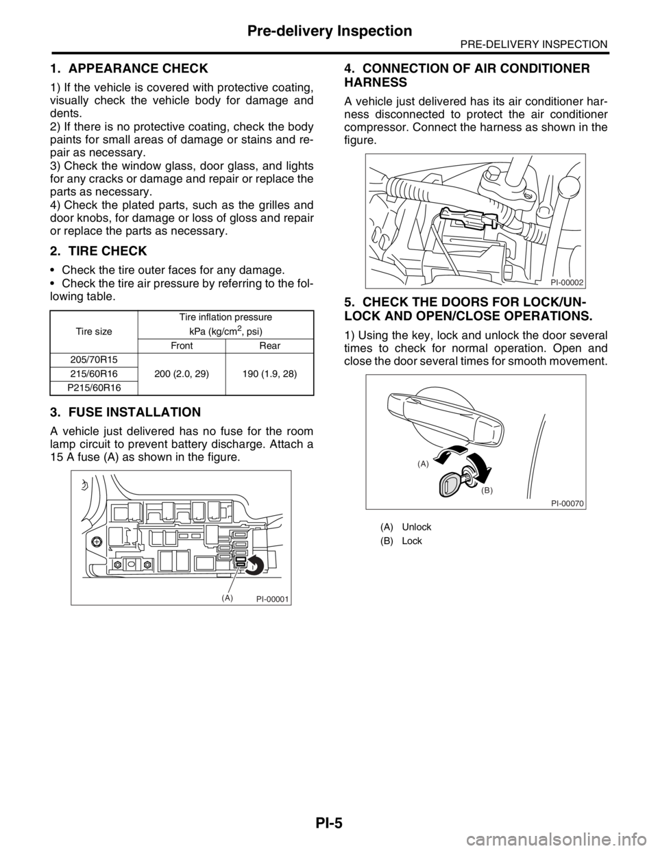
3. FUSE INSTALLATION
A vehicle just delivered has no fuse for the room
lamp circuit to prevent battery discharge. Attach a
15 A fuse (A) as shown in the figure.
4. CONNECTION OF AIR CONDITIONER
HARNESS
A vehicle just delivered has its air conditioner har-
ness disconnected to protect the air conditioner
compressor. Connect the harness as shown in the
figure.
5. CHECK THE DOORS FOR LOCK/UN-
LOCK AND OPEN/CLOSE OPERATIONS.
1) Using the key, lock and unlock the door several
times to check for normal operation. Open and
close the door several times for smooth movement.Tire sizeTire inflation pressure
kPa (kg/cm2, psi)
Front Rear
205/70R15
200 (2.0, 29) 190 (1.9, 28) 215/60R16
P215/60R16
PI-00001(A)
(A) Unlock
(B) Lock
PI-00002
PI-00070
(A)
(B)
Page 779 of 2870

PM-42
PERIODIC MAINTENANCE SERVICE
Steering System (Power Steering)
(2) Retighten the adjusting screw to 7.4 N·m
(0.75 kgf-m, 5.4 ft-lb) and back off 25°.
(3) Apply Liquid gasket to at least 1/3 of entire
perimeter of adjusting screw thread.
(4) Install the lock nut. While holding the adjust-
ing screw with a wrench, tighten the lock nut us-
ing ST.
ST 926230000 SPANNER
Tightening torque (Lock nut):
39 N·m (4.0 kgf-m, 29 ft-lb)
Hold the adjusting screw with a wrench to pre-
vent it from turning it, while tightening the lock
nut.
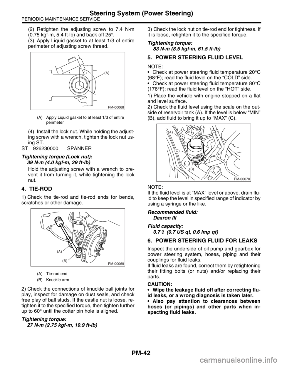
4. TIE-ROD
1) Check the tie-rod and tie-rod ends for bends,
scratches or other damage.
2) Check the connections of knuckle ball joints for
play, inspect for damage on dust seals, and check
free play of ball studs. If the castle nut is loose, re-
tighten it to the specified torque, then tighten further
up to 60° until the cotter pin hole is aligned.
Tightening torque:
27 N·m (2.75 kgf-m, 19.9 ft-lb)3) Check the lock nut on tie-rod end for tightness. If
it is loose, retighten it to the specified torque.
Tightening torque:
83 N·m (8.5 kgf-m, 61.5 ft-lb)
5. POWER STEERING FLUID LEVEL
NOTE:
Check at power steering fluid temperature 20°C
(68°F); read the fluid level on the “COLD” side.
Check at power steering fluid temperature 80°C
(176°F); read the fluid level on the “HOT” side.
1) Place the vehicle with engine stopped on a flat
and level surface.
2) Check the fluid level using the scale on the out-
side of reservoir tank (A). If the level is below “MIN”
(B), add fluid to bring it up to “MAX” (C).
NOTE:
If the fluid level is at “MAX” level or above, drain flu-
id to keep the level in specified range of indicator by
using a syringe or the like.
Recommended fluid:
Dexron III
Fluid capacity:
0.72 (0.7 US qt, 0.6 Imp qt)
6. POWER STEERING FLUID FOR LEAKS
Inspect the underside of oil pump and gearbox for
power steering system, hoses, piping and their
couplings for fluid leaks.
If fluid leaks are found, correct them by retightening
their fitting bolts (or nuts) and/or replacing their
parts.
CAUTION:
Wipe the leakage fluid off after correcting flu-
id leaks, or a wrong diagnosis is taken later.
Also pay attention to clearances between
hoses (or pipings) and other parts when in-
specting fluid leaks.
(A) Apply Liquid gasket to at least 1/3 of entire
perimeter
(A) Tie-rod end
(B) Knuckle arm
PM-00068
(A)
PM-00069
(A)
(B)
PM-00070
(A)
(C)
(B)