Page 120 of 2870
AB-20
AIRBAG SYSTEM
Roll Connector
9. Roll Connector
A: REMOVAL
1) Turn the ignition switch to OFF.
2) Disconnect the ground cable from battery, and
wait for at least 20 seconds before starting work.
3) Remove the driver’s airbag module.
14, Driver’s Airbag Module.>
4) Remove the steering wheel.
MOVAL, Steering Wheel.>
5) Remove the steering column cover.
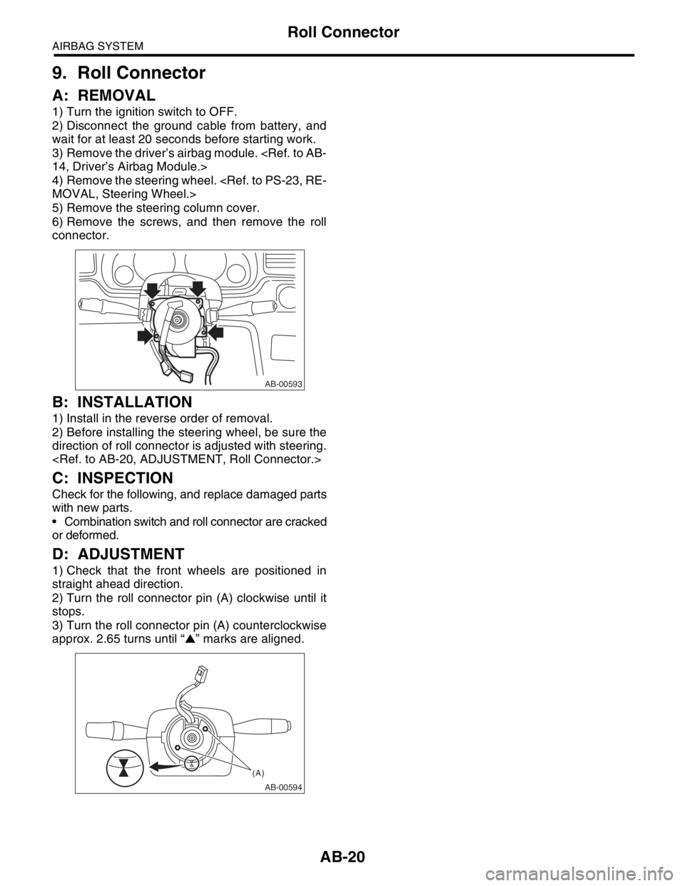
6) Remove the screws, and then remove the roll
connector.
B: INSTALLATION
1) Install in the reverse order of removal.
2) Before installing the steering wheel, be sure the
direction of roll connector is adjusted with steering.
C: INSPECTION
Check for the following, and replace damaged parts
with new parts.
Combination switch and roll connector are cracked
or deformed.
D: ADJUSTMENT
1) Check that the front wheels are positioned in
straight ahead direction.
2) Turn the roll connector pin (A) clockwise until it
stops.
3) Turn the roll connector pin (A) counterclockwise
approx. 2.65 turns until “▲” marks are aligned.
AB-00593
AB-00594
(A)
Page 665 of 2870
FUJI HEAVY INDUSTRIES LTD. G8080GE6
2004 FORESTER SERVICE MANUAL QUICK REFERENCE INDEX
CHASSIS SECTION
This service manual has been prepared
to provide SUBARU service personnel
with the necessary information and data
for the correct maintenance and repair
of SUBARU vehicles.
This manual includes the procedures
for maintenance, disassembling, reas-
sembling, inspection and adjustment of
components and diagnostics for guid-
ance of experienced mechanics.
Please peruse and utilize this manual
fully to ensure complete repair work for
satisfying our customers by keeping
their vehicle in optimum condition.
When replacement of parts during
repair work is needed, be sure to use
SUBARU genuine parts.
All information, illustration and specifi-
cations contained in this manual are
based on the latest product information
available at the time of publication
approval.FRONT SUSPENSION FS
REAR SUSPENSION RS
WHEEL AND TIRE SYSTEM WT
DIFFERENTIAL DI
TRANSFER CASE TC
DRIVE SHAFT SYSTEM DS
ABS ABS
ABS (DIAGNOSTIC) ABS
BRAKE BR
PARKING BRAKE PB
POWER ASSISTED SYSTEM
(POWER STEERING)PS
Page 2408 of 2870
4AT-95
AUTOMATIC TRANSMISSION
Transfer Clutch
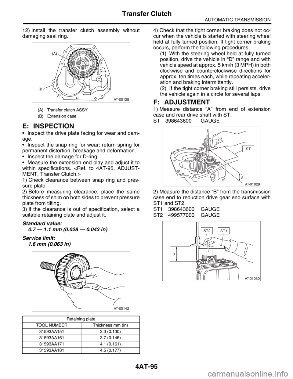
12) Install the transfer clutch assembly without
damaging seal ring.
E: INSPECTION
Inspect the drive plate facing for wear and dam-
age.
Inspect the snap ring for wear; return spring for
permanent distortion, breakage and deformation.
Inspect the damage for D-ring.
Measure the extension end play and adjust it to
within specifications.
MENT, Transfer Clutch.>
1) Check clearance between snap ring and pres-
sure plate.
2) Before measuring clearance, place the same
thickness of shim on both sides to prevent pressure
plate from tilting.
3) If the clearance is out of specification, select a
suitable retaining plate and adjust it.
Standard value:
0.7 — 1.1 mm (0.028 — 0.043 in)
Service limit:
1.6 mm (0.063 in)4) Check that the tight corner braking does not oc-
cur when the vehicle is started with steering wheel
held at fully turned position. If tight corner braking
occurs, perform the following procedures.
(1) With the steering wheel held at fully turned
position, drive the vehicle in “D” range and with
vehicle speed at approx. 5 km/h (3 MPH) in both
clockwise and counterclockwise directions for
approx. ten times each, while repeating acceler-
ation and braking intermittently.
(2) If the tight corner braking still persists, drive
the vehicle again in a circle for several laps.
F: ADJUSTMENT
1) Measure distance “A” from end of extension
case and rear drive shaft with ST.
ST 398643600 GAUGE
2) Measure the distance “B” from the transmission
case end to reduction drive gear end surface with
ST1 and ST2.
ST1 398643600 GAUGE
ST2 499577000 GAUGE(A) Transfer clutch ASSY
(B) Extension case
Retaining plate
TOOL NUMBER Thickness mm (in)
31593AA151 3.3 (0.130)
31593AA161 3.7 (0.146)
31593AA171 4.1 (0.161)
31593AA181 4.5 (0.177)
AT-00125
(A)
(B)
AT-00142
AST
AT-01029
ST2ST1
B
AT-01030