2004 SUBARU FORESTER checking oil
[x] Cancel search: checking oilPage 136 of 2870

AB-4
AIRBAG SYSTEM (DIAGNOSTIC)
General Description
3. General Description
A: CAUTION
When servicing a vehicle, be sure to turn the ig-
nition switch to OFF, disconnect the ground cable
from battery, and wait for more than 20 seconds
before starting work.
The airbag system is fitted with a backup power
source. If the airbag system is serviced within 20
seconds after the ground cable is disconnected, it
may inflate.
If sensors, airbag module, airbag control module,
pretensioner, and harness are deformed or dam-
aged, replace them with new genuine parts.
Do not use the airbag system and pretensioners
on other vehicles. When replacing parts, be sure to
replace them with new parts.
When checking the system, be sure to use a dig-
ital circuit tester. Use of an analog circuit tester may
cause the airbag to activate erroneously. When checking, use a test harness. Do not di-
rectly apply the tester probe to any connector termi-
nal of the airbag.
Do not drop the airbag modulator parts, subject
them to high temperature over 93°C (199°F), or let
water, oil, or grease get on them; otherwise, the in-
ternal parts may be damaged and reliability greatly
lowered.
AB-00002
AB-00120
AB-00121
(1) Test harness
AB-00122
(1)
AB-00123
Page 317 of 2870
ET-7
ENTERTAINMENT
Antenna
6. Antenna
A: INSPECTION
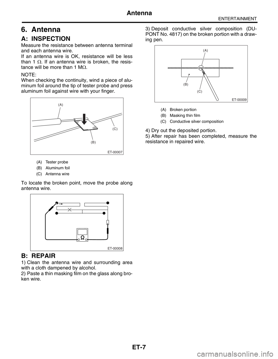
Measure the resistance between antenna terminal
and each antenna wire.
If an antenna wire is OK, resistance will be less
than 1 Ω. If an antenna wire is broken, the resis-
tance will be more than 1 MΩ.
NOTE:
When checking the continuity, wind a piece of alu-
minum foil around the tip of tester probe and press
aluminum foil against wire with your finger.
To locate the broken point, move the probe along
antenna wire.
B: REPAIR
1) Clean the antenna wire and surrounding area
with a cloth dampened by alcohol.
2) Paste a thin masking film on the glass along bro-
ken wire.3) Deposit conductive silver composition (DU-
PONT No. 4817) on the broken portion with a draw-
ing pen.
4) Dry out the deposited portion.
5) After repair has been completed, measure the
resistance in repaired wire.
(A) Tester probe
(B) Aluminum foil
(C) Antenna wire
ET-00007
(B)(C) (A)
ET-00008
(A) Broken portion
(B) Masking thin film
(C) Conductive silver composition
(B)
(C)
ET-00009
(A)
Page 735 of 2870
PI-12
PRE-DELIVERY INSPECTION
Pre-delivery Inspection
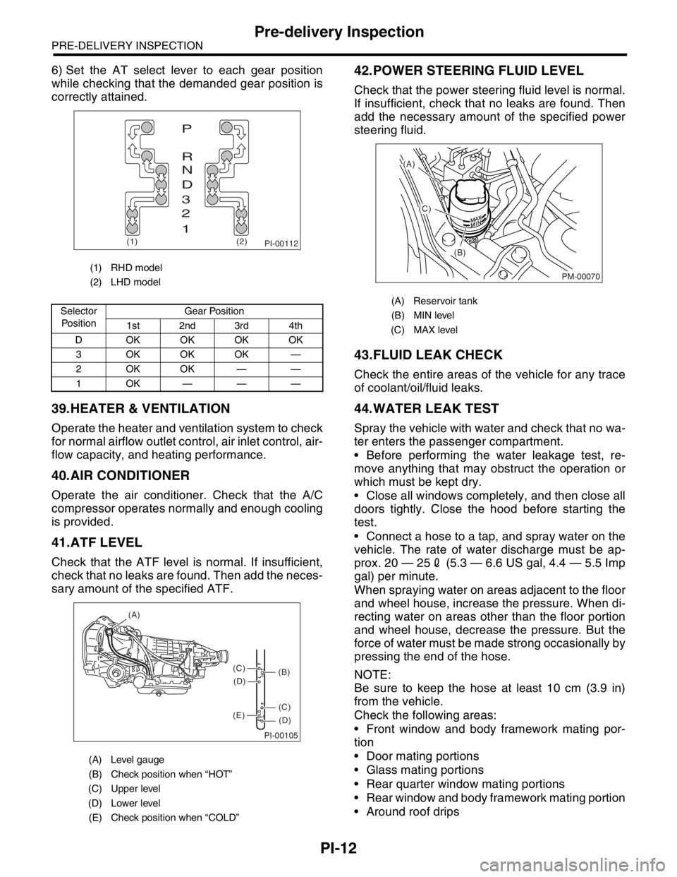
6) Set the AT select lever to each gear position
while checking that the demanded gear position is
correctly attained.
39.HEATER & VENTILATION
Operate the heater and ventilation system to check
for normal airflow outlet control, air inlet control, air-
flow capacity, and heating performance.
40.AIR CONDITIONER
Operate the air conditioner. Check that the A/C
compressor operates normally and enough cooling
is provided.
41.ATF LEVEL
Check that the ATF level is normal. If insufficient,
check that no leaks are found. Then add the neces-
sary amount of the specified ATF.
42.POWER STEERING FLUID LEVEL
Check that the power steering fluid level is normal.
If insufficient, check that no leaks are found. Then
add the necessary amount of the specified power
steering fluid.
43.FLUID LEAK CHECK
Check the entire areas of the vehicle for any trace
of coolant/oil/fluid leaks.
44.WATER LEAK TEST
Spray the vehicle with water and check that no wa-
ter enters the passenger compartment.
Before performing the water leakage test, re-
move anything that may obstruct the operation or
which must be kept dry.
Close all windows completely, and then close all
doors tightly. Close the hood before starting the
test.
Connect a hose to a tap, and spray water on the
vehicle. The rate of water discharge must be ap-
prox. 20 — 252 (5.3 — 6.6 US gal, 4.4 — 5.5 Imp
gal) per minute.
When spraying water on areas adjacent to the floor
and wheel house, increase the pressure. When di-
recting water on areas other than the floor portion
and wheel house, decrease the pressure. But the
force of water must be made strong occasionally by
pressing the end of the hose.
NOTE:
Be sure to keep the hose at least 10 cm (3.9 in)
from the vehicle.
Check the following areas:
Front window and body framework mating por-
tion
Door mating portions
Glass mating portions
Rear quarter window mating portions
Rear window and body framework mating portion
Around roof drips
(1) RHD model
(2) LHD model
Selector
Po si t io nGear Position
1st 2nd 3rd 4th
D OKOKOKOK
3 OKOKOK —
2OKOK——
1OK———
(A) Level gauge
(B) Check position when “HOT”
(C) Upper level
(D) Lower level
(E) Check position when “COLD”
PI-00112(1) (2)
P
R
N
D
3
2
1
PI-00105
COLD
LFHOT LF
(A)
(C)
(D)
(C)
(D)
(E)
(B)
(A) Reservoir tank
(B) MIN level
(C) MAX level
PM-00070
(A)
(C)
(B)
Page 745 of 2870
PM-8
PERIODIC MAINTENANCE SERVICE
Engine Oil
7) Fill engine oil through the filler pipe up to center
between upper lever and lower level. Make sure
that the vehicle is placed level when checking oil
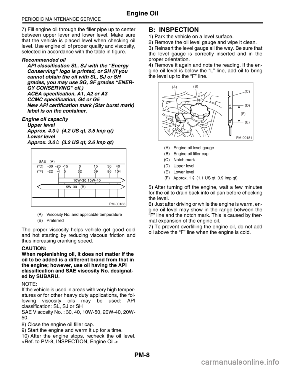
level. Use engine oil of proper quality and viscosity,
selected in accordance with the table in figure.
Recommended oil
API classification SL, SJ with the “Energy
Conserving” logo is printed, or SH (if you
cannot obtain the oil with SL, SJ or SH
grades, you may use SG, SF grades “ENER-
GY CONSERVING” oil.)
ACEA specification, A1, A2 or A3
CCMC specification, G4 or G5
New API certification mark (Star burst mark)
label is on the container.
Engine oil capacity
Upper level
Approx. 4.02 (4.2 US qt, 3.5 Imp qt)
Lower level
Approx. 3.02 (3.2 US qt, 2.6 Imp qt)
The proper viscosity helps vehicle get good cold
and hot starting by reducing viscous friction and
thus increasing cranking speed.
CAUTION:
When replenishing oil, it does not matter if the
oil to be added is a different brand from that in
the engine; however, use oil having the API
classification and SAE viscosity No. designat-
ed by SUBARU.
NOTE:
If the vehicle is used in areas with very high temper-
atures or for other heavy duty applications, the fol-
lowing viscosity oils may be used: API
classification: SL, SJ or SH
SAE Viscosity No. : 30, 40, 10W-50, 20W-40, 20W-
50.
8) Close the engine oil filler cap.
9) Start the engine and warm it up for a time.
10) After the engine stops, recheck the oil level.
1) Park the vehicle on a level surface.
2) Remove the oil level gauge and wipe it clean.
3) Reinsert the level gauge all the way. Be sure that
the level gauge is correctly inserted and in the
proper orientation.
4) Remove it again and note the reading. If the en-
gine oil level is below the “L” line, add oil to bring
the level up to the “F” line.
5) After turning off the engine, wait a few minutes
for the oil to drain back into oil pan before checking
the level.
6) Just after driving or while the engine is warm, en-
gine oil level may show in the range between the
“F” line and the notch mark. This is caused by ther-
mal expansion of the engine oil.
7) To prevent overfilling the engine oil, do not add
oil above the “F” line when the engine is cold.
(A) Viscosity No. and applicable temperature
(B) Preferred
PM-00188
40 30 15 0 -15 -20 -30 ( C)
104 86 59 32
10W-30,10W-40 5 -4 -22 ( F)
SAE (A)
5W-30 (B)
(A) Engine oil level gauge
(B) Engine oil filler cap
(C) Notch mark
(D) Upper level
(E) Lower level
(F) Approx. 12 (1.1 US qt, 0.9 Imp qt)
PM-00181
(A)(B)
(D)
(E) (F)(C)
Page 763 of 2870
PM-26
PERIODIC MAINTENANCE SERVICE
ATF
16.ATF
A: INSPECTION
CAUTION:
The level of ATF varies with fluid temperature.
Pay attention to the fluid temperature when
checking ATF level.
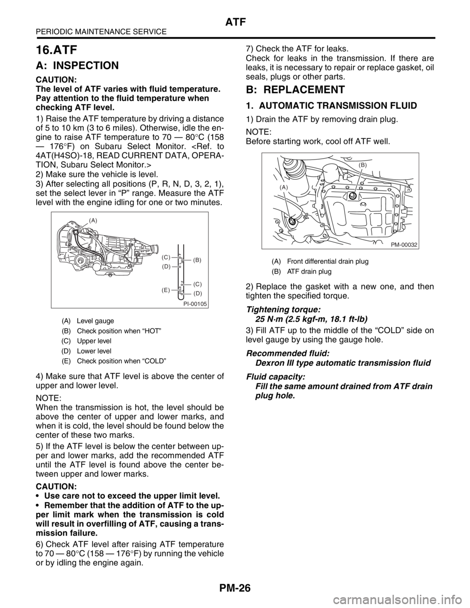
1) Raise the ATF temperature by driving a distance
of 5 to 10 km (3 to 6 miles). Otherwise, idle the en-
gine to raise ATF temperature to 70 — 80°C (158
— 176°F) on Subaru Select Monitor.
TION, Subaru Select Monitor.>
2) Make sure the vehicle is level.
3) After selecting all positions (P, R, N, D, 3, 2, 1),
set the select lever in “P” range. Measure the ATF
level with the engine idling for one or two minutes.
4) Make sure that ATF level is above the center of
upper and lower level.
NOTE:
When the transmission is hot, the level should be
above the center of upper and lower marks, and
when it is cold, the level should be found below the
center of these two marks.
5) If the ATF level is below the center between up-
per and lower marks, add the recommended ATF
until the ATF level is found above the center be-
tween upper and lower marks.
CAUTION:
Use care not to exceed the upper limit level.
Remember that the addition of ATF to the up-
per limit mark when the transmission is cold
will result in overfilling of ATF, causing a trans-
mission failure.
6) Check ATF level after raising ATF temperature
to 70 — 80°C (158 — 176°F) by running the vehicle
or by idling the engine again.7) Check the ATF for leaks.
Check for leaks in the transmission. If there are
leaks, it is necessary to repair or replace gasket, oil
seals, plugs or other parts.
B: REPLACEMENT
1. AUTOMATIC TRANSMISSION FLUID
1) Drain the ATF by removing drain plug.
NOTE:
Before starting work, cool off ATF well.
2) Replace the gasket with a new one, and then
tighten the specified torque.
Tightening torque:
25 N·m (2.5 kgf-m, 18.1 ft-lb)
3) Fill ATF up to the middle of the “COLD” side on
level gauge by using the gauge hole.
Recommended fluid:
Dexron III type automatic transmission fluid
Fluid capacity:
Fill the same amount drained from ATF drain
plug hole.
(A) Level gauge
(B) Check position when “HOT”
(C) Upper level
(D) Lower level
(E) Check position when “COLD”
PI-00105
COLD
LFHOT LF
(A)
(C)
(D)
(C)
(D)
(E)
(B)(A) Front differential drain plug
(B) ATF drain plug
PM-00032
(B)
(A)
Page 954 of 2870
ME(H4SO)-83
MECHANICAL
Cylinder Block
D: ASSEMBLY
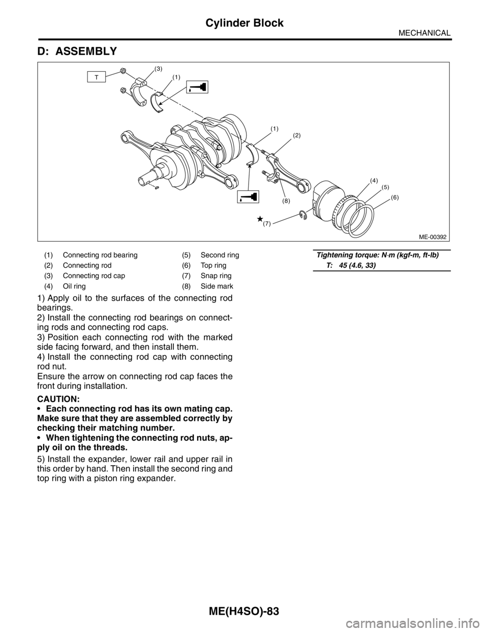
1) Apply oil to the surfaces of the connecting rod
bearings.
2) Install the connecting rod bearings on connect-
ing rods and connecting rod caps.
3) Position each connecting rod with the marked
side facing forward, and then install them.
4) Install the connecting rod cap with connecting
rod nut.
Ensure the arrow on connecting rod cap faces the
front during installation.
CAUTION:
Each connecting rod has its own mating cap.
Make sure that they are assembled correctly by
checking their matching number.
When tightening the connecting rod nuts, ap-
ply oil on the threads.
5) Install the expander, lower rail and upper rail in
this order by hand. Then install the second ring and
top ring with a piston ring expander.
(1) Connecting rod bearing (5) Second ringTightening torque: N⋅m (kgf-m, ft-lb)
(2) Connecting rod (6) Top ringT: 45 (4.6, 33)
(3) Connecting rod cap (7) Snap ring
(4) Oil ring (8) Side mark
ME-00392
(2)
(4)
(5)
(6)
(1)
(1)
(7)(8) (3)T
Page 1038 of 2870
LU(H4SO)-10
LUBRICATION
Engine Oil
3. Engine Oil
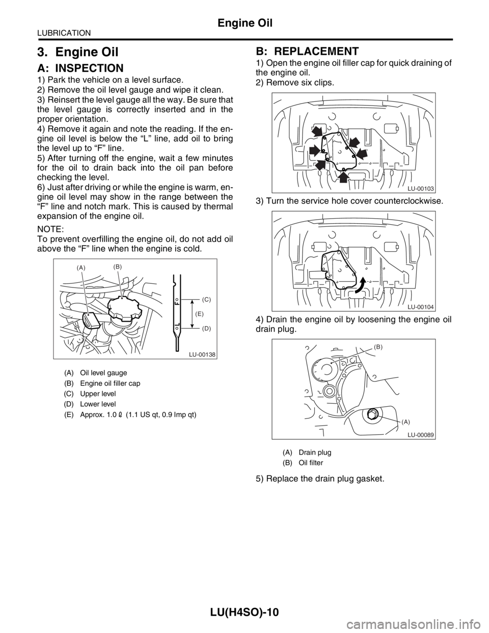
A: INSPECTION
1) Park the vehicle on a level surface.
2) Remove the oil level gauge and wipe it clean.
3) Reinsert the level gauge all the way. Be sure that
the level gauge is correctly inserted and in the
proper orientation.
4) Remove it again and note the reading. If the en-
gine oil level is below the “L” line, add oil to bring
the level up to “F” line.
5) After turning off the engine, wait a few minutes
for the oil to drain back into the oil pan before
checking the level.
6) Just after driving or while the engine is warm, en-
gine oil level may show in the range between the
“F” line and notch mark. This is caused by thermal
expansion of the engine oil.
NOTE:
To prevent overfilling the engine oil, do not add oil
above the “F” line when the engine is cold.
B: REPLACEMENT
1) Open the engine oil filler cap for quick draining of
the engine oil.
2) Remove six clips.
3) Turn the service hole cover counterclockwise.
4) Drain the engine oil by loosening the engine oil
drain plug.
5) Replace the drain plug gasket.
(A) Oil level gauge
(B) Engine oil filler cap
(C) Upper level
(D) Lower level
(E) Approx. 1.02 (1.1 US qt, 0.9 Imp qt)
LU-00138
(A)(B)
(C)
(D) (E)
(A) Drain plug
(B) Oil filter
LU-00103
LU-00104
LU-00089
(B)
(A)
Page 1039 of 2870
LU(H4SO)-11
LUBRICATION
Engine Oil
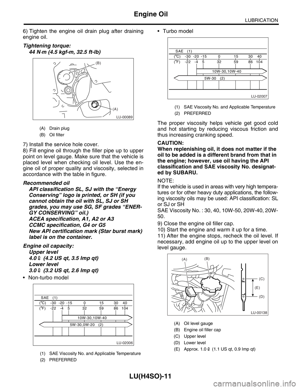
6) Tighten the engine oil drain plug after draining
engine oil.
Tightening torque:
44 N
⋅m (4.5 kgf-m, 32.5 ft-lb)
7) Install the service hole cover.
8) Fill engine oil through the filler pipe up to upper
point on level gauge. Make sure that the vehicle is
placed level when checking oil level. Use the en-
gine oil of proper quality and viscosity, selected in
accordance with the table in figure.
Recommended oil
API classification SL, SJ with the “Energy
Conserving” logo is printed, or SH (if you
cannot obtain the oil with SL, SJ or SH
grades, you may use SG, SF grades “ENER-
GY CONSERVING” oil.)
ACEA specification, A1, A2 or A3
CCMC specification, G4 or G5
New API certification mark (Star burst mark)
label is on the container.
Engine oil capacity:
Upper level
4.02 (4.2 US qt, 3.5 Imp qt)
Lower level
3.02 (3.2 US qt, 2.6 Imp qt)
Non-turbo model Turbo model
The proper viscosity helps vehicle get good cold
and hot starting by reducing viscous friction and
thus increasing cranking speed.
CAUTION:
When replenishing oil, it does not matter if the
oil to be added is a different brand from that in
the engine; however, use oil having the API
classification and SAE viscosity No. designat-
ed by SUBARU.
NOTE:
If the vehicle is used in areas with very high tempera-
tures or for other heavy duty applications, the follow-
ing viscosity oils may be used: API classification: SL
or SJ or SH
SAE Viscosity No. : 30, 40, 10W-50, 20W-40, 20W-
50.
9) Close the engine oil filler cap.
10) Start the engine and warm it up for a time.
11) After the engine stops, recheck the oil level. If
necessary, add engine oil up to the upper level on
level gauge.
(A) Drain plug
(B) Oil filter
(1) SAE Viscosity No. and Applicable Temperature
(2) PREFERRED
LU-00089
(B)
(A)
LU-02006
40 30 15 0 -15 -20 -30 ( C)
104 86 59 32
10W-30,10W-40 5 -4 -22 ( F)
SAE (1)
5W-30,0W-20 (2)
(1) SAE Viscosity No. and Applicable Temperature
(2) PREFERRED
(A) Oil level gauge
(B) Engine oil filler cap
(C) Upper level
(D) Lower level
(E) Approx. 1.02 (1.1 US qt, 0.9 Imp qt)
LU-02007
40 30 15 0 -15 -20 -30 ( C)
104 86 59 32 5 -4 -22 ( F)
SAE (1)
10W-30,10W-40
5W-30 (2)
LU-00138
(A)(B)
(C)
(D) (E)