2004 SUBARU FORESTER checking oil
[x] Cancel search: checking oilPage 1094 of 2870
SC(H4SO)-19
STARTING/CHARGING SYSTEM
Generator
E: INSPECTION
1. DIODE
CAUTION:
Never use a mega tester (measuring use for
high voltage) or any other similar measure for
this test; otherwise, the diodes may be dam-
aged.
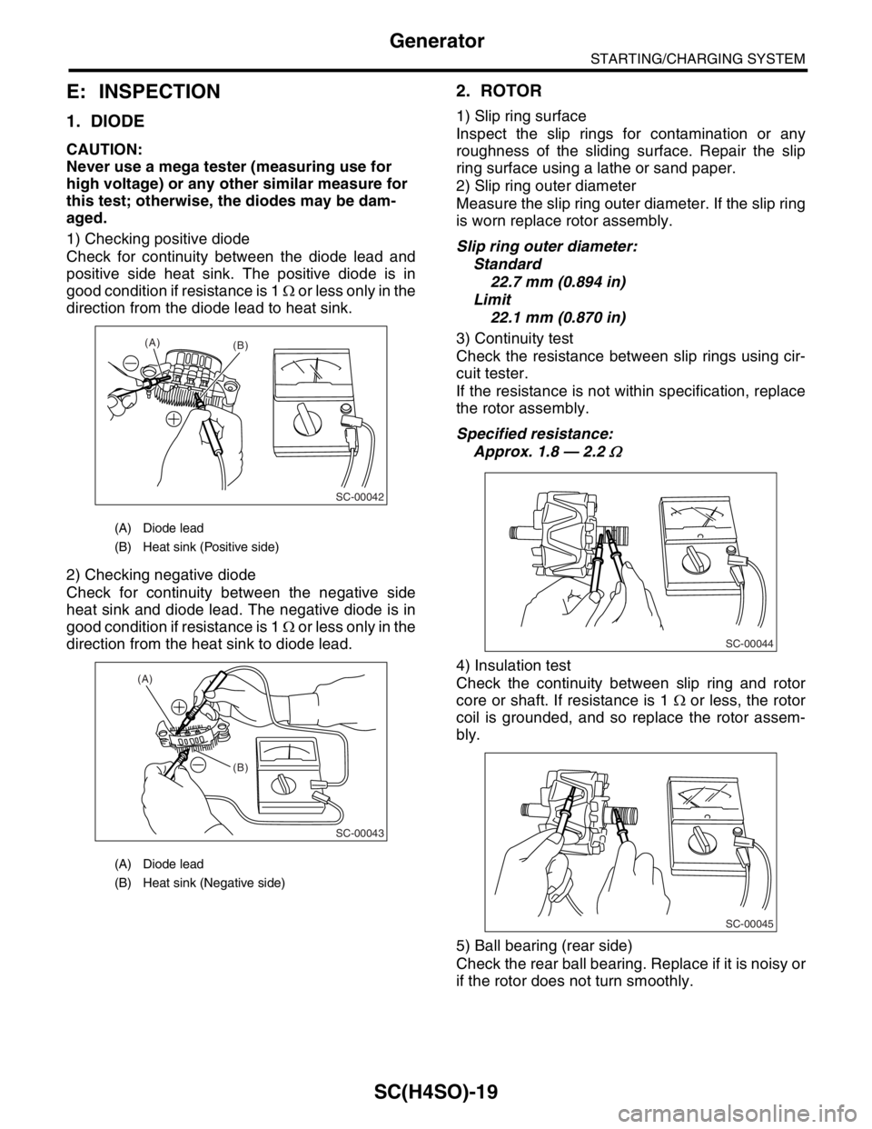
1) Checking positive diode
Check for continuity between the diode lead and
positive side heat sink. The positive diode is in
good condition if resistance is 1 Ω or less only in the
direction from the diode lead to heat sink.
2) Checking negative diode
Check for continuity between the negative side
heat sink and diode lead. The negative diode is in
good condition if resistance is 1 Ω or less only in the
direction from the heat sink to diode lead.
2. ROTOR
1) Slip ring surface
Inspect the slip rings for contamination or any
roughness of the sliding surface. Repair the slip
ring surface using a lathe or sand paper.
2) Slip ring outer diameter
Measure the slip ring outer diameter. If the slip ring
is worn replace rotor assembly.
Slip ring outer diameter:
Standard
22.7 mm (0.894 in)
Limit
22.1 mm (0.870 in)
3) Continuity test
Check the resistance between slip rings using cir-
cuit tester.
If the resistance is not within specification, replace
the rotor assembly.
Specified resistance:
Approx. 1.8 — 2.2
Ω
4) Insulation test
Check the continuity between slip ring and rotor
core or shaft. If resistance is 1 Ω or less, the rotor
coil is grounded, and so replace the rotor assem-
bly.
5) Ball bearing (rear side)
Check the rear ball bearing. Replace if it is noisy or
if the rotor does not turn smoothly.
(A) Diode lead
(B) Heat sink (Positive side)
(A) Diode lead
(B) Heat sink (Negative side)
(A)
(B)
SC-00042
(B) (A)
SC-00043
SC-00044
SC-00045
Page 1095 of 2870
SC(H4SO)-20
STARTING/CHARGING SYSTEM
Generator
3. STARTOR
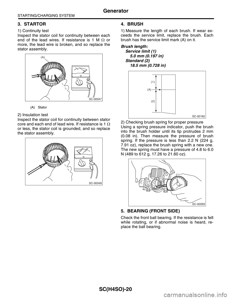
1) Continuity test
Inspect the stator coil for continuity between each
end of the lead wires. If resistance is 1 M Ω or
more, the lead wire is broken, and so replace the
stator assembly.
2) Insulation test
Inspect the stator coil for continuity between stator
core and each end of lead wire. If resistance is 1 Ω
or less, the stator coil is grounded, and so replace
the stator assembly.
4. BRUSH
1) Measure the length of each brush. If wear ex-
ceeds the service limit, replace the brush. Each
brush has the service limit mark (A) on it.
Brush length:
Service limit (1)
5.0 mm (0.197 in)
Standard (2)
18.5 mm (0.728 in)
2) Checking brush spring for proper pressure
Using a spring pressure indicator, push the brush
into the brush holder until its tip protrudes 2 mm
(0.08 in). Then measure the pressure of brush
spring. If the pressure is less than 2.2 N (224 g,
7.91 oz), replace the brush spring with a new one.
The new spring must have a pressure of 4.8 to 6.0
N (489 to 612 g, 17.26 to 21.60 oz).
5. BEARING (FRONT SIDE)
Check the front ball bearing. If the resistance is felt
while rotating, or if abnormal noise is heard, re-
place the ball bearing.
(A) Stator
(A)
SC-00047
SC-00048
SC-00162
(A)
(1)
(2)
SC-00093
Page 1565 of 2870
ME(H4DOTC)-105
MECHANICAL
Cylinder Block
D: ASSEMBLY
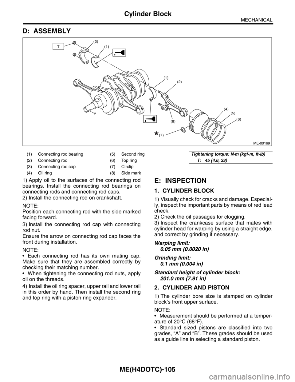
1) Apply oil to the surfaces of the connecting rod
bearings. Install the connecting rod bearings on
connecting rods and connecting rod caps.
2) Install the connecting rod on crankshaft.
NOTE:
Position each connecting rod with the side marked
facing forward.
3) Install the connecting rod cap with connecting
rod nut.
Ensure the arrow on connecting rod cap faces the
front during installation.
NOTE:
Each connecting rod has its own mating cap.
Make sure that they are assembled correctly by
checking their matching number.
When tightening the connecting rod nuts, apply
oil on the threads.
4) Install the oil ring spacer, upper rail and lower rail
in this order by hand. Then install the second ring
and top ring with a piston ring expander.E: INSPECTION
1. CYLINDER BLOCK
1) Visually check for cracks and damage. Especial-
ly, inspect the important parts by means of red lead
check.
2) Check the oil passages for clogging.
3) Inspect the crankcase surface that mates with
cylinder head for warping by using a straight edge,
and correct by grinding if necessary.
Warping limit:
0.05 mm (0.0020 in)
Grinding limit:
0.1 mm (0.004 in)
Standard height of cylinder block:
201.0 mm (7.91 in)
2. CYLINDER AND PISTON
1) The cylinder bore size is stamped on cylinder
block’s front upper surface.
NOTE:
Measurement should be performed at a temper-
ature of 20°C (68°F).
Standard sized pistons are classified into two
grades, “A” and “B”. These grades should be used
as a guide line in selecting a standard piston.
(1) Connecting rod bearing (5) Second ringTightening torque: N⋅m (kgf-m, ft-lb)
(2) Connecting rod (6) Top ringT: 45 (4.6, 33)
(3) Connecting rod cap (7) Circlip
(4) Oil ring (8) Side mark
ME-00169
(2)
(4)
(5)
(6)
(1)
(1)
(7)(8) (3)T
Page 2342 of 2870
4AT-30
AUTOMATIC TRANSMISSION
Automatic Transmission Fluid
2. Automatic Transmission Flu-
id
A: INSPECTION
NOTE:
The level of ATF varies with fluid temperature. Pay
attention to the ATF temperature when checking
ATF level.
1) Raise the ATF temperature by driving a distance
of 5 to 10 km (3 to 6 miles). Otherwise, idle the en-
gine to raise ATF temperature to 70 — 80°C (158
— 176°F) on Subaru Select Monitor.
TION, Subaru Select Monitor.>
2) Make sure the vehicle is level.
3) After selecting all positions (P, R, N, D, 3, 2, 1),
set the select lever in “P” range. Measure the ATF
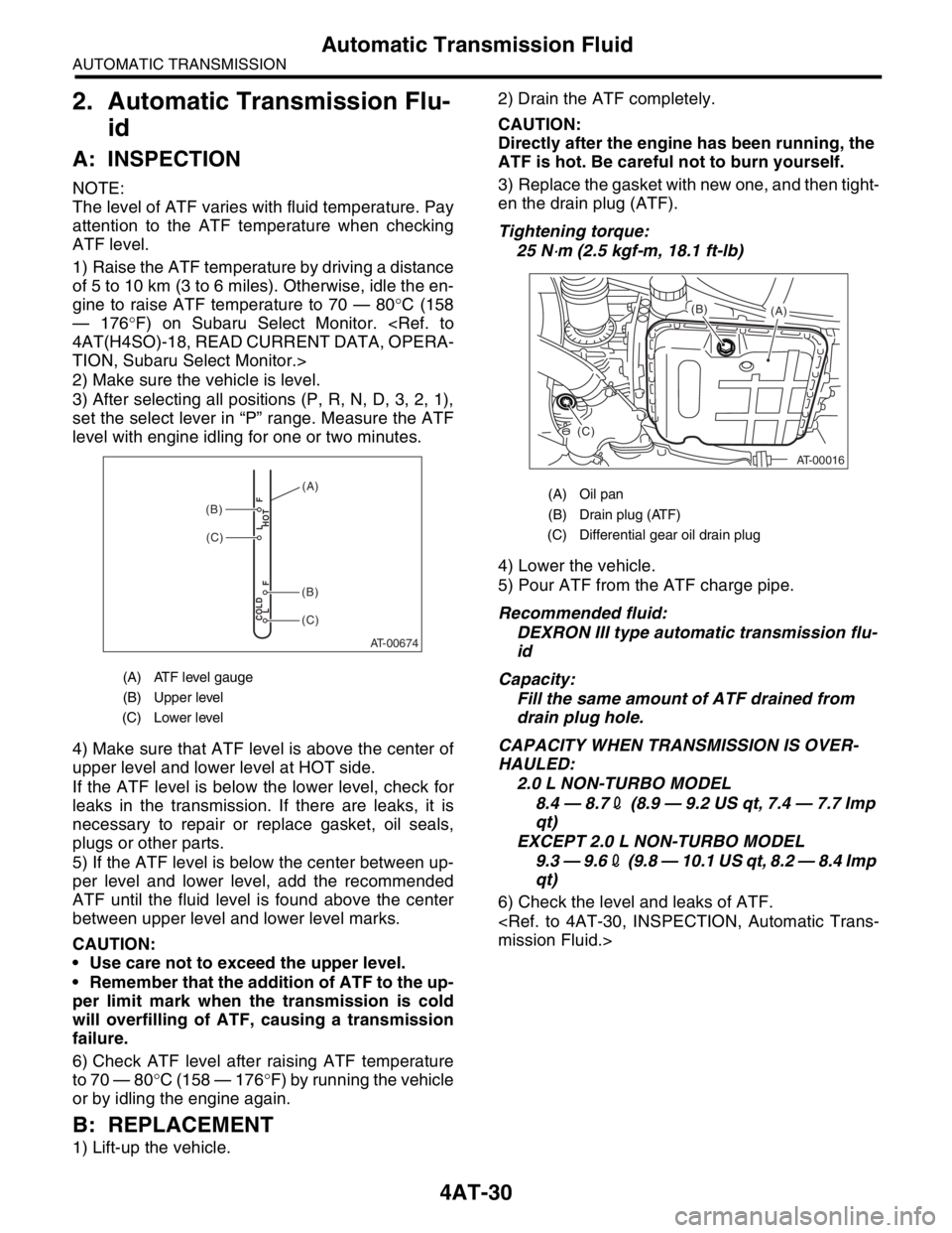
level with engine idling for one or two minutes.
4) Make sure that ATF level is above the center of
upper level and lower level at HOT side.
If the ATF level is below the lower level, check for
leaks in the transmission. If there are leaks, it is
necessary to repair or replace gasket, oil seals,
plugs or other parts.
5) If the ATF level is below the center between up-
per level and lower level, add the recommended
ATF until the fluid level is found above the center
between upper level and lower level marks.
CAUTION:
Use care not to exceed the upper level.
Remember that the addition of ATF to the up-
per limit mark when the transmission is cold
will overfilling of ATF, causing a transmission
failure.
6) Check ATF level after raising ATF temperature
to 70 — 80°C (158 — 176°F) by running the vehicle
or by idling the engine again.
B: REPLACEMENT
1) Lift-up the vehicle.2) Drain the ATF completely.
CAUTION:
Directly after the engine has been running, the
ATF is hot. Be careful not to burn yourself.
3) Replace the gasket with new one, and then tight-
en the drain plug (ATF).
Tightening torque:
25 N
⋅m (2.5 kgf-m, 18.1 ft-lb)
4) Lower the vehicle.
5) Pour ATF from the ATF charge pipe.
Recommended fluid:
DEXRON III type automatic transmission flu-
id
Capacity:
Fill the same amount of ATF drained from
drain plug hole.
CAPACITY WHEN TRANSMISSION IS OVER-
HAULED:
2.0 L NON-TURBO MODEL
8.4 — 8.72 (8.9 — 9.2 US qt, 7.4 — 7.7 Imp
qt)
EXCEPT 2.0 L NON-TURBO MODEL
9.3 — 9.62 (9.8 — 10.1 US qt, 8.2 — 8.4 Imp
qt)
6) Check the level and leaks of ATF.
(A) ATF level gauge
(B) Upper level
(C) Lower level
AT-00674
COLD
LFHOT LF
(C)
(C)
(B)
(B)
(A)(A) Oil pan
(B) Drain plug (ATF)
(C) Differential gear oil drain plug
AT-00016
(A) (B)
(C)
Page 2344 of 2870

4AT-32
AUTOMATIC TRANSMISSION
Road Test
4. Road Test
A: INSPECTION
1. GENERAL PRECAUTION
Road tests should be conducted to properly diag-
nose the condition of the automatic transmission.
NOTE:
When performing the test, do not exceed posted
speed limit.
2. D RANGE SHIFT FUNCTION
Check shifting between 1st ←→ 2nd ←→ 3rd ←→
4th while driving on normal city streets.
3. D RANGE SHIFT SHOCK
Check the shock level when shifting up during nor-
mal driving.
4. KICK-DOWN FUNCTION
Check kick-down for each gear. Also check the
kick-down shock level.
5. ENGINE BRAKE OPERATION
Check the 3rd gear engine brake when shifting
down from D ←→ 3rd range while driving in 4th
gear of D range [50 — 60 km/h (31 — 37 MPH)].
Check the 2nd gear engine brake when shifting
between 3rd ←→ 2nd range while driving in the 3rd
range of 3rd gear [40 — 50 km/h (25 — 31 MPH)].
Check the 1st gear engine brake when shifting
between 2nd ←→ 1st range while driving in the 2nd
range of 2nd gear [20 — 30 km/h (12 — 19 MPH)].
6. LOCK-UP FUNCTION
Check that rpm does not change sharply when
the axle pedal is lightly depressed when driving on
flat roads at 60 km/h (37 MPH).
Check slip lock-up with following procedure.
Subaru Select Monitor is needed for checking (EC,
EK model).
Before start checking, check that the DTC is not ex-
isted using Subaru Select Monitor. When the DTC
is existed, perform the collective action with DTC
and check that the DTC is not existed again, and
then start the checking.
1) The check performed on flat and straight road or
free roller.
NOTE:
Slip lock-up does not operate when the vehicle is
lifted up, because of not occurring surface resis-
tance.
Also checking on the free roller, check with de-
pressing foot brake lightly to make the checking
easier, because the surface resistance will be defi-
cient2) Connect the Subaru Select Monitor.
3) Check ATF temperature using Subaru Select
Monitor.
NOTE:
ATF temperature is between 50 — 100°C (122
— 212°F).
When the temperature is low, warm-up the ATF
by running the vehicle or etc.
4) Start the engine, and make the lock-up duty be
able to read on data display of Subaru Select Mon-
itor.
5) 35 — 40 Drive the vehicle at a constant speed of
35 — 40 km/h (22 — 25 MPH).
6) Read the lock-up duty while vehicle is running.
Standard value:
25 — 45%
NOTE:
On the free roller, the value sometimes lowers.
Slip lock-up control is not operating when the
lock-up duty is less than 5%, or when the lock-up
duty goes down immediately after starts rise. On
these cases, improper ATF or deterioration of ATF
may be the cause. Check the amount of ATF or re-
place them, and then recheck it.
7. P RANGE OPERATION
Stop the vehicle on an uphill grade of 5% or more
and shift to “P” range. Check that the vehicle does
not move when the parking brake is released.
8. NOISE AND VIBRATION
Check for unusual sounds and vibration while driv-
ing and during shifting.
9. CLIMBING CONTROL FUNCTION
Check that the gear remains in 3rd when going
up a grade.
Check that the gear remains in 3rd when apply-
ing the brakes while going down a grade.
10.TRANSFER CLUTCH
Check tight corner braking when the vehicle started
with steering fully turned.
11.OIL LEAKS
After the driving test, inspect for oil leaks.
Page 2428 of 2870
4AT-114
AUTOMATIC TRANSMISSION
Drive Pinion Shaft Assembly
10) Select three or less shims from following table.
E: INSPECTION
Make sure that all component parts are free of
harmful cut, gouges, and other faults.
Adjust the teeth alignment.
F: ADJUSTMENT
1) Remove the liquid gasket completely.
2) Install the oil pump housing assembly to torque
converter clutch case, and secure them with tight-
ening four bolts evenly.
NOTE:
Use an old gasket or an aluminum washer so as not
to damage the mating surface of housing.
Tightening torque:
41 N
⋅m (4.2 kgf-m, 30.4 ft-lb)
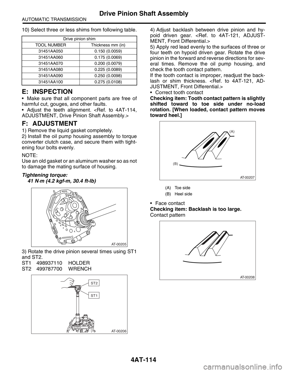
3) Rotate the drive pinion several times using ST1
and ST2.
ST1 498937110 HOLDER
ST2 499787700 WRENCH4) Adjust backlash between drive pinion and hy-
poid driven gear.
5) Apply red lead evenly to the surfaces of three or
four teeth on hypoid driven gear. Rotate the drive
pinion in the forward and reverse directions for sev-
eral times. Remove the oil pump housing, and
check the tooth contact pattern.
If the tooth contact is improper, readjust the back-
lash or shim thickness.
Correct tooth contact
Checking item: Tooth contact pattern is slightly
shifted toward to toe side under no-load
rotation. [When loaded, contact pattern moves
toward heel.]
Face contact
Checking item: Backlash is too large.
Contact pattern
Drive pinion shim
TOOL NUMBER Thickness mm (in)
31451AA050 0.150 (0.0059)
31451AA060 0.175 (0.0069)
31451AA070 0.200 (0.0079)
31451AA080 0.225 (0.0089)
31451AA090 0.250 (0.0098)
31451AA100 0.275 (0.0108)
AT-00205
AT-00206
ST2
ST1
(A) Toe side
(B) Heel side
AT-00207
(A)
(B)
AT-00208
Page 2779 of 2870
5MT-66
MANUAL TRANSMISSION AND DIFFERENTIAL
Transmission Case
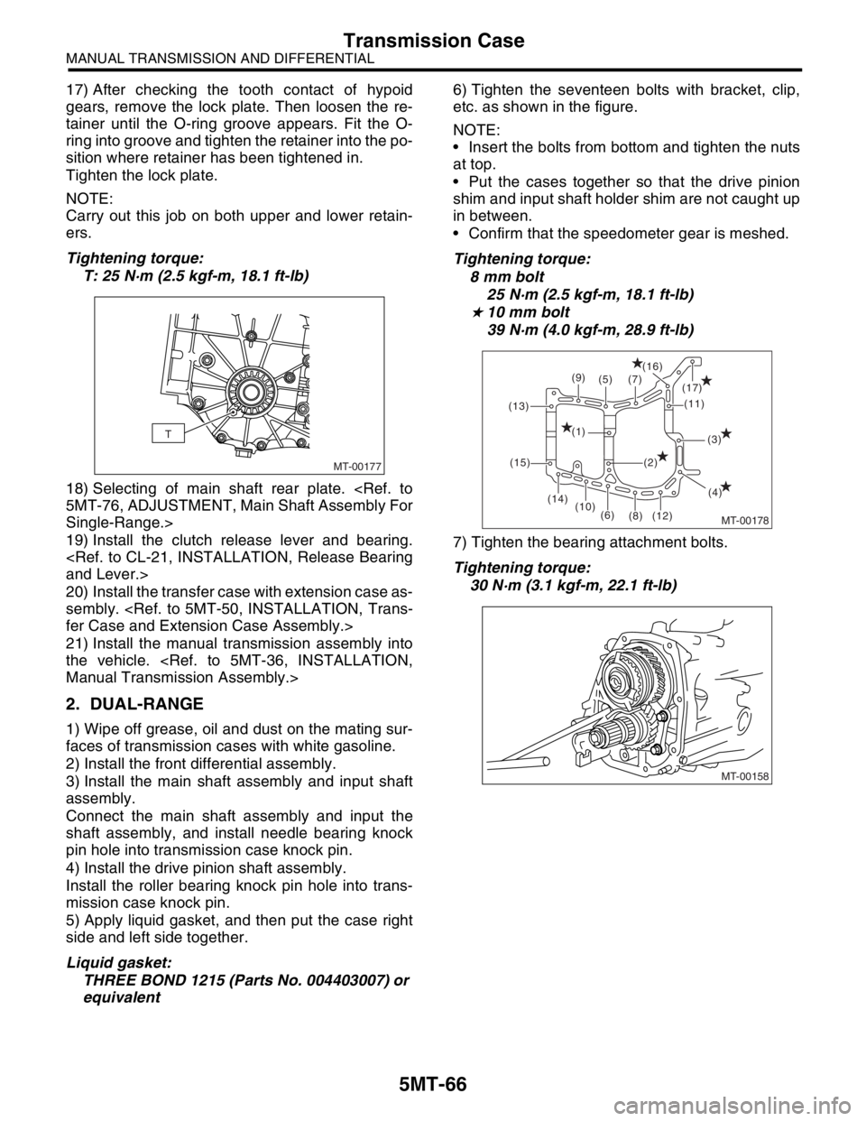
17) After checking the tooth contact of hypoid
gears, remove the lock plate. Then loosen the re-
tainer until the O-ring groove appears. Fit the O-
ring into groove and tighten the retainer into the po-
sition where retainer has been tightened in.
Tighten the lock plate.
NOTE:
Carry out this job on both upper and lower retain-
ers.
Tightening torque:
T: 25 N·m (2.5 kgf-m, 18.1 ft-lb)
18) Selecting of main shaft rear plate.
Single-Range.>
19) Install the clutch release lever and bearing.
20) Install the transfer case with extension case as-
sembly.
21) Install the manual transmission assembly into
the vehicle.
2. DUAL-RANGE
1) Wipe off grease, oil and dust on the mating sur-
faces of transmission cases with white gasoline.
2) Install the front differential assembly.
3) Install the main shaft assembly and input shaft
assembly.
Connect the main shaft assembly and input the
shaft assembly, and install needle bearing knock
pin hole into transmission case knock pin.
4) Install the drive pinion shaft assembly.
Install the roller bearing knock pin hole into trans-
mission case knock pin.
5) Apply liquid gasket, and then put the case right
side and left side together.
Liquid gasket:
THREE BOND 1215 (Parts No. 004403007) or
equivalent6) Tighten the seventeen bolts with bracket, clip,
etc. as shown in the figure.
NOTE:
Insert the bolts from bottom and tighten the nuts
at top.
Put the cases together so that the drive pinion
shim and input shaft holder shim are not caught up
in between.
Confirm that the speedometer gear is meshed.
Tightening torque:
8 mm bolt
25 N·m (2.5 kgf-m, 18.1 ft-lb)
★ 10 mm bolt
39 N·m (4.0 kgf-m, 28.9 ft-lb)
7) Tighten the bearing attachment bolts.
Tightening torque:
30 N·m (3.1 kgf-m, 22.1 ft-lb)
MT-00177
T
MT-00178
(9)
(7) (5)(16)
(17)
(11)
(3)
(4) (2) (1)
(12) (8) (6) (10) (14) (15) (13)
MT-00158
Page 2781 of 2870
5MT-68
MANUAL TRANSMISSION AND DIFFERENTIAL
Transmission Case
16) Turn the transmission main shaft several times
while tapping around the retainer lightly with plastic
hammer.
17) Inspect and adjust the backlash and tooth con-
tact of hypoid gear.
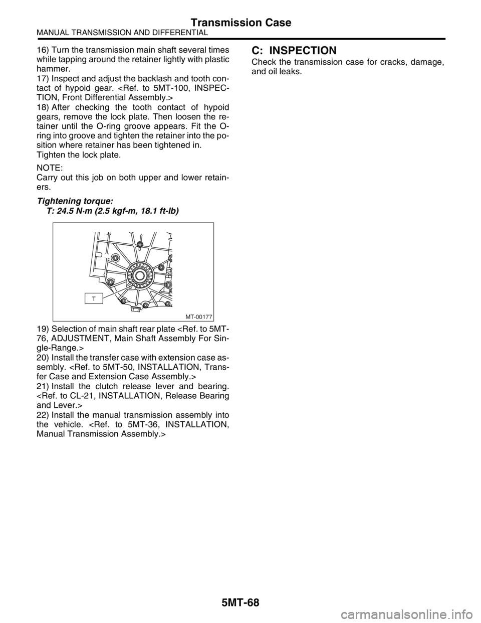
18) After checking the tooth contact of hypoid
gears, remove the lock plate. Then loosen the re-
tainer until the O-ring groove appears. Fit the O-
ring into groove and tighten the retainer into the po-
sition where retainer has been tightened in.
Tighten the lock plate.
NOTE:
Carry out this job on both upper and lower retain-
ers.
Tightening torque:
T: 24.5 N·m (2.5 kgf-m, 18.1 ft-lb)
19) Selection of main shaft rear plate
gle-Range.>
20) Install the transfer case with extension case as-
sembly.
21) Install the clutch release lever and bearing.
22) Install the manual transmission assembly into
the vehicle.
Check the transmission case for cracks, damage,
and oil leaks.
MT-00177
T