2004 SUBARU FORESTER compression ratio
[x] Cancel search: compression ratioPage 691 of 2870

SPC-2
SPECIFICATION
Forester
1. Forester
A: DIMENSIONS
★: With sunroof
B: ENGINE
Model 2.0 L Non-turbo 2.0 L Turbo 2.5 L Non-turbo 2.5 L Turbo
Overall length mm (in) 4,450 (175.2)
Overall width mm (in) 1,735 (68.3)
Overall height (at C.W.) mm (in) 1,590 (62.6) 1,585 (62.4) 1,590 (62.6)
CompartmentLength mm (in) 1,795 (70.7)
Width mm (in) 1,455 (57.3)
Height mm (in)
1,245 (49.0), 1,210 (47.6)
★
Wheelbase mm (in) 2,525 (99.4)
Tread Front mm (in) 1,495 (58.9)
Rear mm (in) 1,485 (58.5)
Minimum road clearance mm (in) 190 (7.5) 195 (7.7) 200 (7.9)
Model 2.0 L Non-turbo 2.0 L Turbo 2.5 L Non-turbo 2.5 L Turbo
Engine type Horizontally opposed, liquid cooled, 4-cylinder, 4-stroke gasoline engine
Valve arrangement Overhead camshaft type
Bore×Stroke mm (in) 92×75 (3.62×2.95) 99.5×79 (3.92×3.11)
Displacement
cm
3 (cu in)1,994 (121.67) 2,457 (149.94)
Compression ratio 10.0±0.2 8.0±0.2 10.0±0.2 8.2±0.2
Firing order 1 — 3 — 2 — 4
Idle speed at Park or Neu-
tral positionrpm 650±100 700±100 650±100 700±100
Maximum output kW (PS)/rpm 92 (125)/5,600 130 (177)/5,600 115 (156)/5,600 155 (211)/5,600
Maximum torque N⋅m (kgf-m, ft-lb)/rpm184 (18.8, 41.4)/
3,600245 (25.0, 55.1)/
3,200223 (22.7, 50.1)/
3,600320 (32.6, 71.8)/
3,600
Page 870 of 2870

MECHANICAL
ME(H4SO)
Page
1. General Description ....................................................................................2
2. Compression .............................................................................................25
3. Idle Speed .................................................................................................26
4. Ignition Timing ...........................................................................................27
5. Intake Manifold Vacuum............................................................................28
6. Engine Oil Pressure ..................................................................................29
7. Fuel Pressure ............................................................................................30
8. Valve Clearance ........................................................................................31
9. Engine Assembly ......................................................................................34
10. Engine Mounting .......................................................................................41
11. Preparation for Overhaul ...........................................................................42
12. V-belt .........................................................................................................43
13. Crank Pulley ..............................................................................................45
14. Timing Belt Cover......................................................................................47
15. Timing Belt ................................................................................................48
16. Cam Sprocket ...........................................................................................53
17. Crank Sprocket .........................................................................................55
18. Valve Rocker Assembly ............................................................................56
19. Camshaft ...................................................................................................58
20. Cylinder Head ...........................................................................................62
21. Cylinder Block ...........................................................................................69
22. Engine Trouble in General ........................................................................91
23. Engine Noise .............................................................................................96
Page 871 of 2870

ME(H4SO)-2
MECHANICAL
General Description
1. General Description
A: SPECIFICATION
NOTE:
STD: Standard I.D.: Inner Diameter O.D.: Outer Diameter US: Undersize OS: Oversize
EngineModel 2.0 L 2.5 L
Ty p eHorizontally opposed, liquid cooled, 4-cylinder, 4-stroke gaso-
line engine
Valve arrangement Belt driven, single over-head camshaft, 4-valve/cylinder
Bore×Stroke mm (in) 92×75 (3.62×2.95)99.5×79.0
(3.917×3.110)
Displacement
cm
3 (cu in)1,994 (121.67) 2,457 (150)
Compression ratio 10.0
Compression pressure
(at 200 — 300 rpm)kPa (kg/cm
2, psi)1,079 — 1,275 (11.0 — 13.0, 156 — 185)
Number of piston rings Pressure ring: 2, Oil ring: 1
Intake valve timingOpen 4° BTDC 1° BTDC
Close 48° ABDC 51° ABDC
Exhaust valve timingOpen 48° BBDC 50° BBDC
Close 4° AT D C 6° AT D C
Valve clearance Intake mm (in) 0.20±0.04 (0.0079±0.0016)
Exhaust mm (in) 0.25±0.04 (0.0098±0.0016)
Idling speed [at neutral position on
MT, or “P” or “N” range on AT]rpm650±100 (No load)
850±100 (A/C switch ON)
Firing order 1 → 3 → 2 → 4
Ignition timing BTDC/rpm 10°±10°/650
Belt
tensioner
adjusterProtrusion of adjuster rod mm (in) 5.7 — 6.7 (0.224 — 0.263)
Belt
tensionerSpacer O.D. mm (in) 17.955 — 17.975 (0.7069 — 0.7077)
Tensioner bush I.D. mm (in) 18.00 — 18.08 (0.7087 — 0.7118)
Clearance between spacer and bush mm (in)STD 0.025 — 0.125 (0.0010 — 0.0049)
Limit 0.175 (0.0069)
Side clearance of spacer mm (in)STD 0.20 — 0.55 (0.0079 — 0.0217)
Limit 0.81 (0.0319)
Valve rocker
armClearance between shaft and arm mm (in)STD 0.020 — 0.054 (0.0008 — 0.0021)
Limit 0.10 (0.0039)
CamshaftBend limit mm (in) 0.025 (0.0010)
Thrust clearance mm (in)STD 0.030 — 0.090 (0.0012 — 0.0035)
Limit 0.10 (0.0039)
Cam lobe height mm (in)2.0 LIntakeSTD 38.732 — 38.832 (1.5249 — 1.5288)
Limit 38.632 (1.5209)
ExhaustSTD 39.259 — 39.359 (1.5456 — 1.5496)
Limit 39.157 (1.5417)
2.5 LIntakeSTD 39.485 — 39.585 (1.5545 — 1.5585)
Limit 39.385 (1.5506)
ExhaustSTD 39.259 — 39.359 (1.5456 — 1.5496)
Limit 39.159 (1.5417)
Camshaft journal O.D. mm (in) 31.928 — 31.945 (1.2570 — 1.2577)
Camshaft journal hole I.D. (Cylinder head) mm (in) 32.000 — 32.018 (1.2598 — 1.2605)
Oil clearance mm (in)STD 0.055 — 0.090 (0.0022 — 0.0035)
Limit 0.10 (0.0039)
Page 892 of 2870

ME(H4SO)-23
MECHANICAL
General Description
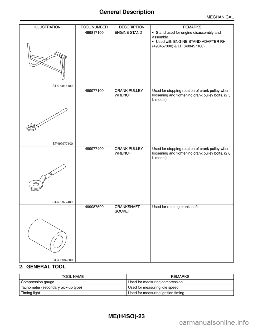
2. GENERAL TOOL
499817100 ENGINE STAND Stand used for engine disassembly and
assembly.
Used with ENGINE STAND ADAPTER RH
(498457000) & LH (498457100).
499977100 CRANK PULLEY
WRENCHUsed for stopping rotation of crank pulley when
loosening and tightening crank pulley bolts. (2.5
L model)
499977400 CRANK PULLEY
WRENCHUsed for stopping rotation of crank pulley when
loosening and tightening crank pulley bolts. (2.0
L model)
499987500 CRANKSHAFT
SOCKETUsed for rotating crankshaft.
TOOL NAME REMARKS
Compression gauge Used for measuring compression.
Tachometer (secondary pick-up type) Used for measuring idle speed.
Timing light Used for measuring ignition timing.ILLUSTRATION TOOL NUMBER DESCRIPTION REMARKS
ST-499817100
ST-499977100
ST-499977400
ST-499987500
Page 894 of 2870

ME(H4SO)-25
MECHANICAL
Compression
2. Compression
A: INSPECTION
CAUTION:
After warming-up, engine becomes very hot. Be
careful not to burn yourself during measure-
ment.
1) After warming-up the engine, turn the ignition
switch to OFF.
2) Make sure that the battery is fully charged.
3) Release the fuel pressure.
TION, Fuel.>
4) Remove all the spark plugs.
5) Fully open the throttle valve.
6) Check the starter motor for satisfactory perfor-
mance and operation.
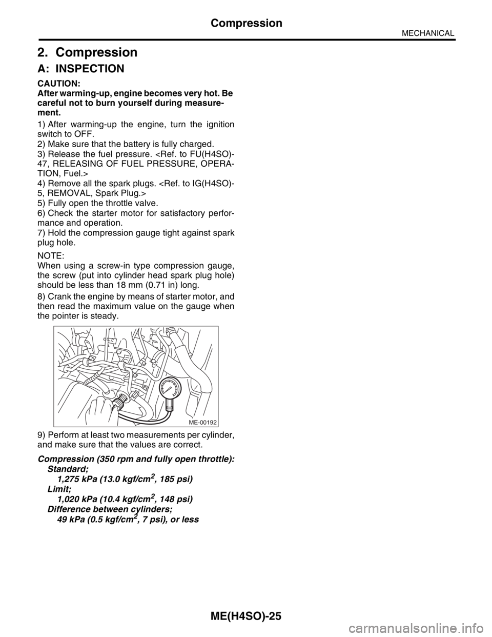
7) Hold the compression gauge tight against spark
plug hole.
NOTE:
When using a screw-in type compression gauge,
the screw (put into cylinder head spark plug hole)
should be less than 18 mm (0.71 in) long.
8) Crank the engine by means of starter motor, and
then read the maximum value on the gauge when
the pointer is steady.
9) Perform at least two measurements per cylinder,
and make sure that the values are correct.
Compression (350 rpm and fully open throttle):
Standard;
1,275 kPa (13.0 kgf/cm
2, 185 psi)
Limit;
1,020 kPa (10.4 kgf/cm
2, 148 psi)
Difference between cylinders;
49 kPa (0.5 kgf/cm
2, 7 psi), or less
ME-00192
Page 923 of 2870

MECHANICAL
ME(H4SO)
Page
1. General Description ....................................................................................2
2. Compression .............................................................................................25
3. Idle Speed .................................................................................................26
4. Ignition Timing ...........................................................................................27
5. Intake Manifold Vacuum............................................................................28
6. Engine Oil Pressure ..................................................................................29
7. Fuel Pressure ............................................................................................30
8. Valve Clearance ........................................................................................31
9. Engine Assembly ......................................................................................34
10. Engine Mounting .......................................................................................41
11. Preparation for Overhaul ...........................................................................42
12. V-belt .........................................................................................................43
13. Crank Pulley ..............................................................................................45
14. Timing Belt Cover......................................................................................47
15. Timing Belt ................................................................................................48
16. Cam Sprocket ...........................................................................................53
17. Crank Sprocket .........................................................................................55
18. Valve Rocker Assembly ............................................................................56
19. Camshaft ...................................................................................................58
20. Cylinder Head ...........................................................................................62
21. Cylinder Block ...........................................................................................69
22. Engine Trouble in General ........................................................................91
23. Engine Noise .............................................................................................96
Page 964 of 2870

ME(H4SO)-93
MECHANICAL
Engine Trouble in General
3. Low output, hesitation and
poor accelerationEngine control system
Intake system Loosened or cracked intake duct A
Loosened or cracked PCV hose A
Loosened or cracked vacuum hose B
Defective intake manifold gasket B
Defective throttle body gasket B
Defective PCV valve B
Loosened oil filler cap B
Dirty air cleaner element A
Fuel line Defective fuel pump and relay B
Clogged fuel line B
Lack of or insufficient fuel C
Belt Defective timing B
Compression Incorrect valve clearance B
Loosened spark plugs or defective gasket B
Loosened cylinder head bolts or defective gasket B
Improper valve seating B
Defective valve stem C
Worn or broken valve spring B
Worn or stuck piston rings, cylinder and piston C
Incorrect valve timing A
Improper engine oil (low viscosity) B
Lubrication system Incorrect oil pressure B
Cooling system Overheating C
Over cooling C
Others Malfunction of evaporative emission control system A
4. Surging Engine control system
Intake system Loosened or cracked intake duct A
Loosened or cracked PCV hose A
Loosened or cracked vacuum hose A
Defective intake manifold gasket B
Defective throttle body gasket B
Defective PCV valve B
Loosened oil filler cap B
Dirty air cleaner element B
Fuel line Defective fuel pump and relay B
Clogged fuel line B
Lack of or insufficient fuel C
Belt Defective timing B
Compression Incorrect valve clearance B
Loosened spark plugs or defective gasket C
Loosened cylinder head bolts or defective gasket C
Improper valve seating C
Defective valve stem C
Worn or broken valve spring C
Worn or stuck piston rings, cylinder and piston C
Incorrect valve timing A
Improper engine oil (low viscosity) B
Cooling system Overheating B
Others Malfunction of evaporative emission control system C TROUBLE PROBLEM PARTS, ETC. POSSIBLE CAUSE RANK
Page 967 of 2870

ME(H4SO)-96
MECHANICAL
Engine Noise
23.Engine Noise
A: INSPECTION
NOTE*:
When disconnecting fuel injector connector, the malfunction indicator light illuminates and DTC is stored in ECM memory.
Therefore, carry out the clear memory mode
Regular clicking soundSound increases as engine
speed increases. Valve mechanism is defective.
Incorrect valve clearance
Worn valve rocker
Worn camshaft
Broken valve spring
Heavy and dull clankOil pressure is low. Worn crankshaft main bearing
Worn connecting rod bearing (big end)
Oil pressure is normal. Loose flywheel mounting bolts
Damaged engine mounting
High-pitched clank (Spark
knock)Sound is noticeable when
accelerating with an overload. Ignition timing advanced
Accumulation of carbon inside combustion chamber
Wrong spark plug
Improper gasoline
Clank when engine speed is
medium (1,000 to 2,000 rpm).Sound is reduced when fuel
injector connector of noisy cyl-
inder is disconnected.
(NOTE*) Worn crankshaft main bearing
Worn bearing at crankshaft end of connecting rod
Knocking sound when engine
is operating under idling speed
and engine is warmSound is reduced when fuel
injector connector of noisy cyl-
inder is disconnected.
(NOTE*) Worn cylinder liner and piston ring
Broken or stuck piston ring
Worn piston pin and hole at piston end of connecting rod
Sound is not reduced if each
fuel injector connector is dis-
connected in turn. (NOTE*) Unusually worn valve lifter
Worn cam gear
Worn camshaft journal bore in crankcase
Squeaky sound — Insufficient generator lubrication
Rubbing sound — Defective generator brush and rotor contact
Gear scream when starting
engine— Defective ignition starter switch
Worn gear and starter pinion
Sound like polishing glass with
a dry cloth— Loose drive belt
Defective water pump shaft
Hissing sound — Loss of compression
Air leakage in air intake system, hoses, connections or mani-
folds
Timing belt noise — Loose timing belt
Belt contacting case/adjacent part
Valve tappet noise — Incorrect valve clearance