2004 SUBARU FORESTER steering wheel
[x] Cancel search: steering wheelPage 112 of 2870

AB-12
AIRBAG SYSTEM
Inspection Locations After a Collision
3. Inspection Locations After a
Collision
A: REPLACEMENT
When airbag system is deployed, replace the fol-
lowing parts.
1. FRONT COLLISION
1) Driver’s airbag module
2) Passenger’s airbag module
3) Driver’s seat belt (pretensioner, lap seat belt pre-
tensioner)
4) Passenger’s seat belt (pretensioner)
5) Airbag control module
6) Front sub-sensor
7) Roll connector
2. SIDE COLLISION
1) Airbag control module
2) Side airbag module (operating side seat bag)
3) Side airbag sensor (operating side)
3. INSPECTION OF OTHER PARTS
Check for the following parts, replace the damaged
parts with new ones.
1) Steering wheel and steering shaft
Check the steering wheel and steering shaft for
mounting condition and deflection of axial and radi-
al direction. Check the steering shaft for deflection
of axial direction with tilt lever released. (After a col-
lision, absorbing part of steering shaft may inflate.)
2) Check the direct type connector of driver’s air-
bag module, pretensioner, etc. for damage, and
also check each harness for pinch and connector
damage. If damage is found, replace the harness
as a unit.
B: INSPECTION
If the vehicle is involved in a collision on any side,
even if it is a slight collision, be sure to check the
following system parts.
1. DRIVER’S AIRBAG MODULE
1) Check for the following, and replace damaged
parts with new ones.
Airbag module is cracked or deformed.
Harness and/or connector is cracked, deformed
or open. Lead wire is exposed.
The module surface is fouled with grease, oil,
water or cleaning solvent.
2) When installing a new driver’s airbag module,
check the following. If necessary, install a new air-
bag module and steering wheel.
The steering wheel is in the way, making it diffi-
cult to install the airbag module. The clearance between the driver’s airbag mod-
ule and steering wheel is not constant.
The steering wheel deformation in axial and radi-
al directions exceed limits.
Specifications:
Height deflection A
Less than 6 mm (0.24 in)
O.D. deflection L
Less than 17 mm (0.67 in)
2. PASSENGER’S AIRBAG MODULE
Check for the following, and replace damaged
parts with new ones.
Airbag module is cracked or deformed.
Harness and/or connector is cracked, deformed
or open. Lead wire is exposed.
Mounting bracket is cracked or deformed.
3. SIDE AIRBAG MODULE
Check for the following, and replace damaged
parts with new ones.
Front seat is damaged or deformed.
Harness and/or connector is cracked, deformed
or open.
Lead wire is exposed.
4. AIRBAG CONTROL MODULE
Check for the following, and replace damaged
parts with new ones.
Control module is cracked or deformed.
Mounting bracket is cracked or deformed.
Connector is scratched or deformed.
Airbag is deployed.
Side airbag is deployed.
AB-00028
L
A
Page 114 of 2870
AB-14
AIRBAG SYSTEM
Driver’s Airbag Module
4. Driver’s Airbag Module
A: REMOVAL
CAUTION:
Refer to “CAUTION” in General Description be-
fore handing the airbag module.
1) Position the front wheels straight ahead. (After
moving the vehicle more than 5 m (16 ft) with front
wheels positioned straight ahead, make sure that
the vehicle moves straight ahead).
2) Turn the ignition switch to OFF.
3) Disconnect the ground cable from battery, and
wait for at least 20 seconds before starting work.
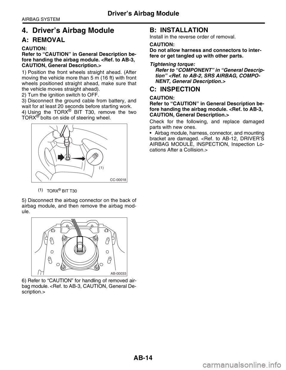
4) Using the TORX
® BIT T30, remove the two
TORX® bolts on side of steering wheel.
5) Disconnect the airbag connector on the back of
airbag module, and then remove the airbag mod-
ule.
6) Refer to “CAUTION” for handling of removed air-
bag module.
B: INSTALLATION
Install in the reverse order of removal.
CAUTION:
Do not allow harness and connectors to inter-
fere or get tangled up with other parts.
Tightening torque:
Refer to “COMPONENT” in “General Descrip-
tion”
C: INSPECTION
CAUTION:
Refer to “CAUTION” in General Description be-
fore handing the airbag module.
Check for the following, and replace damaged
parts with new ones.
Airbag module, harness, connector, and mounting
bracket are damaged.
cations After a Collision.>
(1)
TORX® BIT T30
CC-00018
(1)
AB-00033
Page 120 of 2870
AB-20
AIRBAG SYSTEM
Roll Connector
9. Roll Connector
A: REMOVAL
1) Turn the ignition switch to OFF.
2) Disconnect the ground cable from battery, and
wait for at least 20 seconds before starting work.
3) Remove the driver’s airbag module.
4) Remove the steering wheel.
5) Remove the steering column cover.
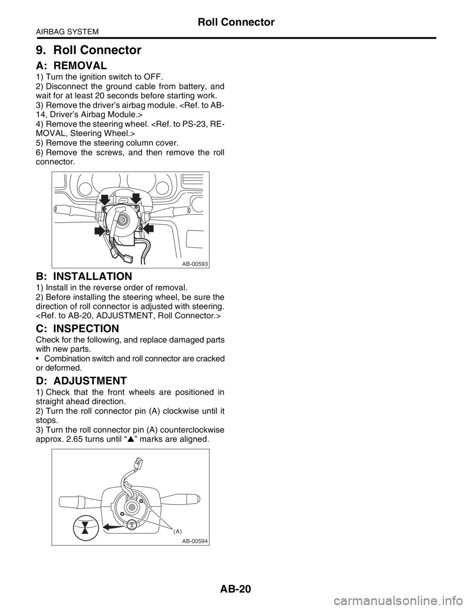
6) Remove the screws, and then remove the roll
connector.
B: INSTALLATION
1) Install in the reverse order of removal.
2) Before installing the steering wheel, be sure the
direction of roll connector is adjusted with steering.
C: INSPECTION
Check for the following, and replace damaged parts
with new parts.
Combination switch and roll connector are cracked
or deformed.
D: ADJUSTMENT
1) Check that the front wheels are positioned in
straight ahead direction.
2) Turn the roll connector pin (A) clockwise until it
stops.
3) Turn the roll connector pin (A) counterclockwise
approx. 2.65 turns until “▲” marks are aligned.
AB-00593
AB-00594
(A)
Page 135 of 2870

AB-3
AIRBAG SYSTEM (DIAGNOSTIC)
Check List for Interview
2. Check List for Interview
A: CHECK
Customer’s Name Inspector’s Name
Date Vehicle Brought In / / Registration No.
Odometer Readingkm
milesVIN
Date Problem Occurred / / Registration Year / /
Weather❏ Fine ❏ Cloudy ❏ Rainy ❏ Snowy ❏ Other:
Temperature°C (°F)
Road Condition❏ Level road❏ Uphill ❏ Downhill❏ Rough road ❏ Others:
Vehicle Operation❏ Starting❏ Idling
❏ Driving (❏ Constant speed❏ Acceleration❏ Deceleration
❏ Steering wheel turn❏ Others: )
Details of Problem
Check Airbag Warning Light❏ Normal (After turning the ignition switch to ON, lit for 7 seconds and goes off.)
❏ Remains ON❏ Remains OFF
Check DTC❏ Normal Code❏ DTC: (Code: )
Page 327 of 2870
COM-5
COMMUNICATION SYSTEM
Horn Switch
4. Horn Switch
A: REMOVAL
WARNING:
Before servicing, be sure to read the notes in
the AB section for proper handling of the driver
airbag module.
1) Disconnect the ground cable from battery.
2) Remove the driver’s airbag module.
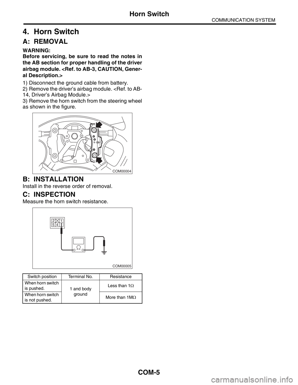
3) Remove the horn switch from the steering wheel
as shown in the figure.
B: INSTALLATION
Install in the reverse order of removal.
C: INSPECTION
Measure the horn switch resistance.
Switch position Terminal No. Resistance
When horn switch
is pushed.
1 and body
groundLess than 1Ω
When horn switch
is not pushed.More than 1MΩ
COM00004
2
5
4
COM00005
1
Page 561 of 2870
CC-9
CRUISE CONTROL SYSTEM
Cruise Control Command Switch
5. Cruise Control Command
Switch
A: REMOVAL
WARNING:
Before servicing, be sure to read the notes in
the AB section for proper handling of the driv-
er’s airbag module.
1) Set the front wheels in straight ahead position.
2) Turn the ignition switch to OFF.
3) Disconnect the ground cable from battery and
wait for at least 20 seconds before starting work.
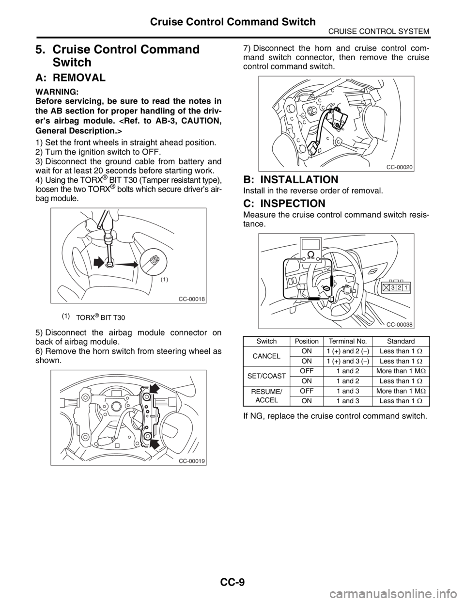
4) Using the TORX
® BIT T30 (Tamper resistant type),
loosen the two TORX® bolts which secure driver’s air-
bag module.
5) Disconnect the airbag module connector on
back of airbag module.
6) Remove the horn switch from steering wheel as
shown.7) Disconnect the horn and cruise control com-
mand switch connector, then remove the cruise
control command switch.
B: INSTALLATION
Install in the reverse order of removal.
C: INSPECTION
Measure the cruise control command switch resis-
tance.
If NG, replace the cruise control command switch.
(1)
TORX® BIT T30
CC-00018
(1)
CC-00019
Switch Position Terminal No. Standard
CANCELON 1 (+) and 2 (−) Less than 1 Ω
ON 1 (+) and 3 (−) Less than 1 Ω
SET/COASTOFF 1 and 2 More than 1 MΩ
ON 1 and 2 Less than 1 Ω
RESUME/
ACCELOFF 1 and 3 More than 1 MΩ
ON 1 and 3 Less than 1 Ω
CC-00020
CC-00038
1 2 3
Page 665 of 2870
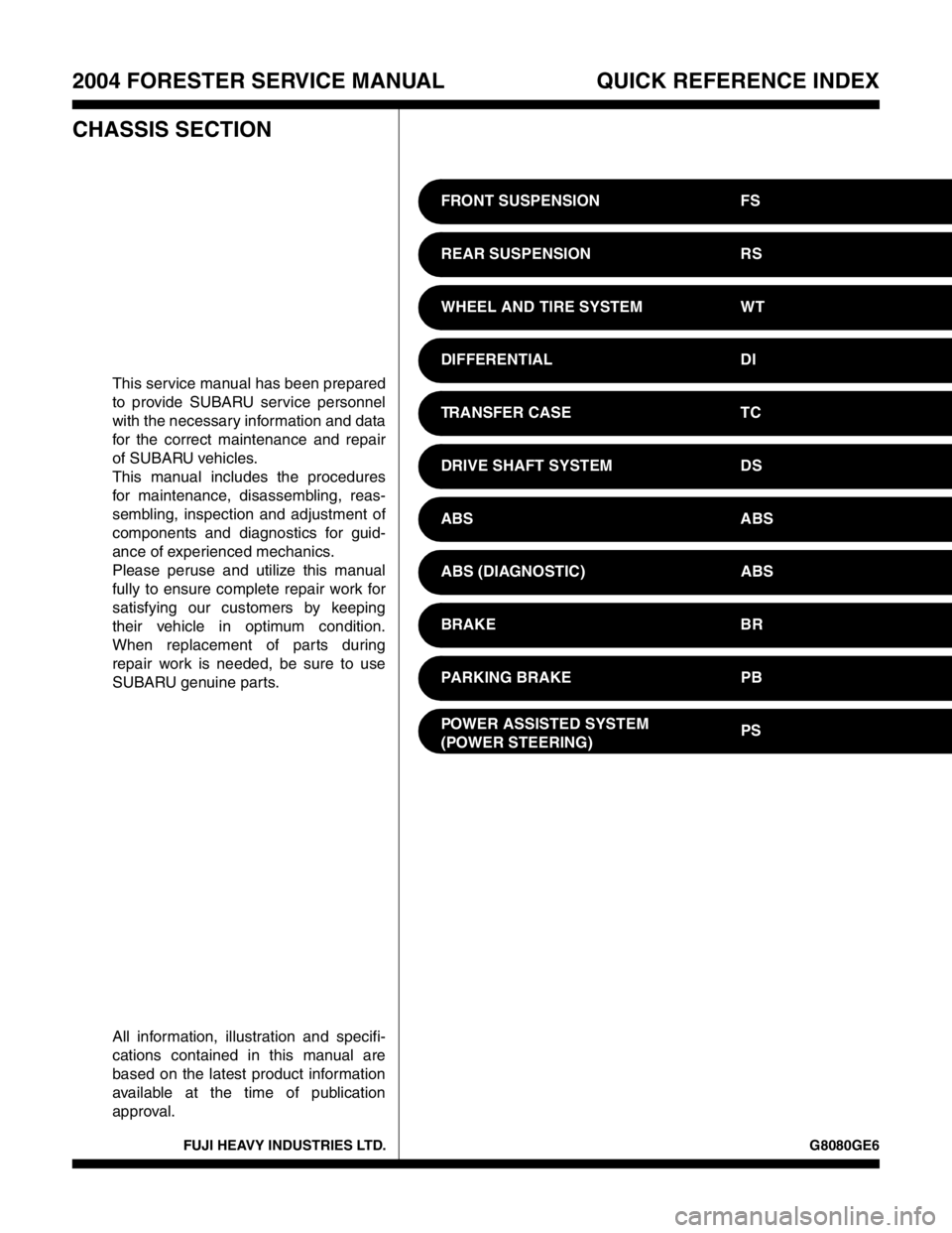
FUJI HEAVY INDUSTRIES LTD. G8080GE6
2004 FORESTER SERVICE MANUAL QUICK REFERENCE INDEX
CHASSIS SECTION
This service manual has been prepared
to provide SUBARU service personnel
with the necessary information and data
for the correct maintenance and repair
of SUBARU vehicles.
This manual includes the procedures
for maintenance, disassembling, reas-
sembling, inspection and adjustment of
components and diagnostics for guid-
ance of experienced mechanics.
Please peruse and utilize this manual
fully to ensure complete repair work for
satisfying our customers by keeping
their vehicle in optimum condition.
When replacement of parts during
repair work is needed, be sure to use
SUBARU genuine parts.
All information, illustration and specifi-
cations contained in this manual are
based on the latest product information
available at the time of publication
approval.FRONT SUSPENSION FS
REAR SUSPENSION RS
WHEEL AND TIRE SYSTEM WT
DIFFERENTIAL DI
TRANSFER CASE TC
DRIVE SHAFT SYSTEM DS
ABS ABS
ABS (DIAGNOSTIC) ABS
BRAKE BR
PARKING BRAKE PB
POWER ASSISTED SYSTEM
(POWER STEERING)PS
Page 694 of 2870

SPC-5
SPECIFICATION
Forester
J: WEIGHT
1. LHD MODEL
★: For the option codes, refer to ID section.
★EC K4 KS
Model 2.0 L Non-turbo 2.5 L Non-turbo
Grade 2.0 X 2.5 X
Transmission 5MT 4AT 5MT 4AT 5MT 4AT
Curb weight (C.W.)Front kgf (lb)760
(1,675)775
(1,710)775
(1,710)790
(1,740)780
(1,720)800
(1,765)
Rear kgf (lb)600
(1,325)600
(1,325)595
(1,310)595
(1,310)620
(1,365)620
(1,365)
Total kgf (lb)1,360
(3,000)1,375
(3,035)1,370
(3,020)1,385
(3,050)1,400
(3,085)1,420
(3,130)
Maximum permissi-
ble axle weight
(M.P.A.W.)Front kgf (lb)1,010
(2,225)1,010
(2,225)1,010
(2,225)1,010
(2,225)1,010
(2,225)1,010
(2,225)
Rear kgf (lb)1,035
(2,280)1,035
(2,280)1,035
(2,280)1,035
(2,280)1,035
(2,280)1,035
(2,280)
Maximum permissi-
ble weight (M.P.W.)Total kgf (lb)1,880
(4,140)1,880
(4,140)1,880
(4,140)1,880
(4,140)1,880
(4,140)1,880
(4,140)
OptionSport package base — — — — — —
Aluminum wheel❍❍❍❍❍❍
Front fog light — — — —❍❍
Cruise control — — — —❍❍
High-grade audio — — — — — —
Sport steering — — — — — —
Leather package base — — — — — —
Leather seat, Leather
door trim——————
Navigation system ——————
Air conditioner — —❍❍❍❍
Side airbag — — — — — —
Sunroof — — — — — —
Self-leveling function Rr❍❍————
Cold area pack A — — — — — —
Cold area pack B — — — — — —
Cold area pack C — — — — — —
Cold area pack D❍❍————
Heated mirrors❍❍————
Security system — — — — — —