2004 SUBARU FORESTER steering wheel
[x] Cancel search: steering wheelPage 741 of 2870

PM-4
PERIODIC MAINTENANCE SERVICE
Schedule
2. EXCEPT FOR EUROPE AREA
For periodic maintenance of over 50,000 km (30,000 miles) or 48 months, carry out inspections by referring
to the following tables. For a maintenance period gone beyond these tables, apply them repeatedly as a set
of 50,000 km (30,000 miles) or 48 months.
For periodic maintenance of over 100,000 km (60,000 miles) or 48 months, carry out inspections by referring
to the following tables. For a maintenance period gone beyond these tables, apply them repeatedly as a set
of 100,000 km (60,000 miles) or 48 months.
Symbols used:
R: Replace
I: Inspection
(I): Recommended service for safe vehicle operation.
N
OTE:
(1) When the vehicle is used in extremely dusty conditions, the air cleaner element should be replaced more often.
(2) ATF filter is a maintenance free part. ATF filter needs replacement, when it is physically damaged or ATF leaked.Maintenance Interval
[Number of months or km (miles), whichever occurs first]
Months 12 24 36 48
Remarks ×1,000 km 5 12.5 25 37.5 50
×1,000 miles 3 7.5 15 22.5 30
1 Engine oil R R R R
2 Engine oil filter R R R R
Maintenance Interval
[Number of months or km (miles), whichever occurs first]
Months 12 24 36 48
Remarks ×1,000 km 1.6 25 50 75 100
×1,000 miles 1 15 30 45 60
3 Spark plugs For Turbo R
Others R R R R
4Drive belt(s) IIII
5 Camshaft drive belt R
6 Fuel line I I
7 Fuel filter R R
8 Air cleaner element I R I R
9 Cooling system I I
10 Coolant R R
11 Clutch system I I I I I
12 Hill-holder system I I I I I
13 Transmission oil R R
14 ATF R R
15 Front & rear differential oil R R
16 Brake line I I
17 Brake fluid R R
18 Disc brake pads & discs I I I I
19 Brake linings and drums I I
20 Parking brake I I I I
21 Suspension I I I I
22 Wheel bearing (I)
23 Axle boots & joints I I I I
24 Steering system (Power steering) I I I I
Page 768 of 2870
PM-31
PERIODIC MAINTENANCE SERVICE
Brake Line
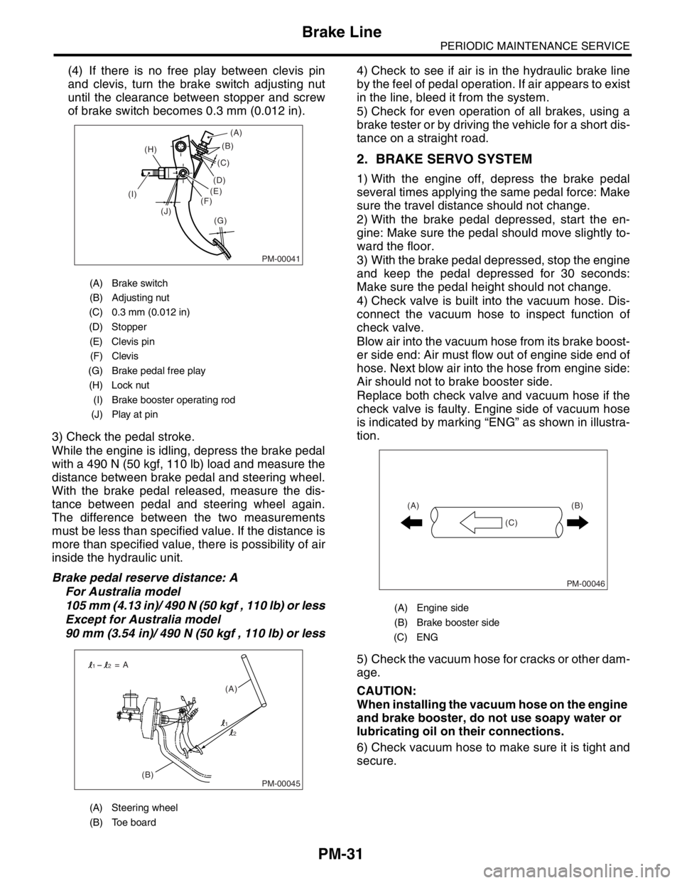
(4) If there is no free play between clevis pin
and clevis, turn the brake switch adjusting nut
until the clearance between stopper and screw
of brake switch becomes 0.3 mm (0.012 in).
3) Check the pedal stroke.
While the engine is idling, depress the brake pedal
with a 490 N (50 kgf, 110 lb) load and measure the
distance between brake pedal and steering wheel.
With the brake pedal released, measure the dis-
tance between pedal and steering wheel again.
The difference between the two measurements
must be less than specified value. If the distance is
more than specified value, there is possibility of air
inside the hydraulic unit.
Brake pedal reserve distance: A
For Australia model
105 mm (4.13 in)/ 490 N (50 kgf , 110 lb) or less
Except for Australia model
90 mm (3.54 in)/ 490 N (50 kgf , 110 lb) or less4) Check to see if air is in the hydraulic brake line
by the feel of pedal operation. If air appears to exist
in the line, bleed it from the system.
5) Check for even operation of all brakes, using a
brake tester or by driving the vehicle for a short dis-
tance on a straight road.
2. BRAKE SERVO SYSTEM
1) With the engine off, depress the brake pedal
several times applying the same pedal force: Make
sure the travel distance should not change.
2) With the brake pedal depressed, start the en-
gine: Make sure the pedal should move slightly to-
ward the floor.
3) With the brake pedal depressed, stop the engine
and keep the pedal depressed for 30 seconds:
Make sure the pedal height should not change.
4) Check valve is built into the vacuum hose. Dis-
connect the vacuum hose to inspect function of
check valve.
Blow air into the vacuum hose from its brake boost-
er side end: Air must flow out of engine side end of
hose. Next blow air into the hose from engine side:
Air should not to brake booster side.
Replace both check valve and vacuum hose if the
check valve is faulty. Engine side of vacuum hose
is indicated by marking “ENG” as shown in illustra-
tion.
5) Check the vacuum hose for cracks or other dam-
age.
CAUTION:
When installing the vacuum hose on the engine
and brake booster, do not use soapy water or
lubricating oil on their connections.
6) Check vacuum hose to make sure it is tight and
secure.
(A) Brake switch
(B) Adjusting nut
(C) 0.3 mm (0.012 in)
(D) Stopper
(E) Clevis pin
(F) Clevis
(G) Brake pedal free play
(H) Lock nut
(I) Brake booster operating rod
(J) Play at pin
(A) Steering wheel
(B) Toe board
PM-00041
(B)
(G) (H)
(I)
(J)(C)
(D)
(E)
(F)(A)
PM-00045(B)(A) = A
1
12
2
(A) Engine side
(B) Brake booster side
(C) ENG
PM-00046
(B)
(C) (A)
Page 774 of 2870

PM-37
PERIODIC MAINTENANCE SERVICE
Suspension
4. WHEEL ALIGNMENT OF FRONT SUS-
PENSION
1) Check the alignment of front suspension to en-
sure that following items conform to standard val-
ues.
Toe-in
Camber angle
Caster angle
Steering angle
2) When the caster angle does not conform to ref-
erence, visually inspect the following components
and replace deformed parts.
Suspension components [Strut assembly, cross-
member, transverse link, etc.]
Body parts to which suspensions are installed.
3) When the toe-in and camber are out of standard
value, adjust them so that they conform to respec-
tive service standard.
ment.>
4) When the right-and-left turning angles of tire are
out of standard, adjust to standard value.
Alignment.>
5. WHEEL ALIGNMENT OF REAR SUS-
PENSION
1) Check the alignment of rear suspension to en-
sure that following items are within standard val-
ues.
Toe-in
Camber angle
Thrust angle
2) When the camber angle does not conform to ref-
erence, visually inspect parts listed below. If defor-
mation is observed, replace the damaged parts.
Suspension components [Shock absorber, front
lateral links, rear lateral links, trailing link, etc.]
Body parts to which suspensions are installed.
3) When the toe-in and thrust angle are out of stan-
dard value, adjust them so that they conform to re-
spective service standard.
ment.>
6. OIL LEAKAGE OF STRUT
Visually inspect the front strut and rear strut for oil
leakage as instructed. If oil leakage reaches under
spring seat lower portion, replace the front strut and
rear strut.
7. TIGHTNESS OF BOLTS AND NUTS
Check the bolts and nuts shown in the figure for
looseness. Retighten the bolts and nuts to speci-
fied torque. If the self-lock nuts and bolts are re-
moved, replace them with new ones.
Front suspension:
Rear suspension:
8. DAMAGE TO SUSPENSION PARTS
Check the following parts and the fastening portion
of the vehicle body for deformation or excessive
rusting which impairs the suspension. Remove the
contaminations on spring seat lower portion with
care because dirt, sand, etc. tend to accumulate on
it. If necessary, replace the damaged parts with
new ones. If minor rust formation, pitting, etc. are
noted, remove the rust and apply remedial anti-cor-
rosion measures.
Front suspension
Transverse link
Crossmember
Strut
Rear suspension
Crossmember
Lateral links
Trailing link
Strut
In the district where salt is sprayed to melt snow
on a road in winter, check suspension parts for
damage caused by rust every 12 months after
lapse of 60 months. Take rust prevention measure
as required.
Page 778 of 2870
PM-41
PERIODIC MAINTENANCE SERVICE
Steering System (Power Steering)
26.Steering System (Power
Steering)
A: INSPECTION
1. STEERING WHEEL
1) Set the steering wheel in a straight-ahead posi-
tion, and check the wheel spokes to make sure
they are correctly set in their specified positions.
2) Lightly turn the steering wheel to the right and
left to determine the point where front wheels start
to move.
Measure the distance of the movement of steering
wheel at the outer periphery of wheel.
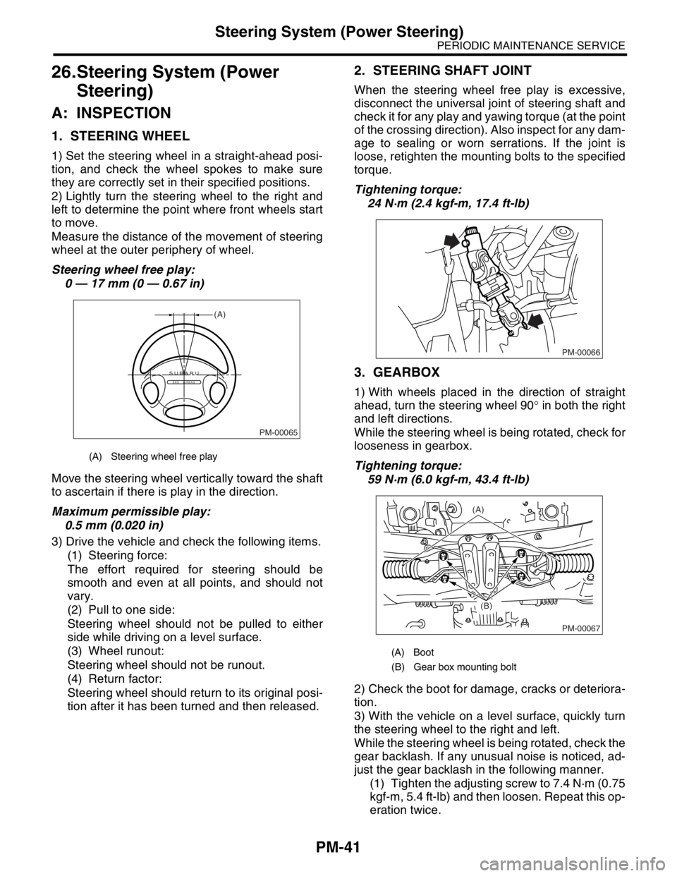
Steering wheel free play:
0 — 17 mm (0 — 0.67 in)
Move the steering wheel vertically toward the shaft
to ascertain if there is play in the direction.
Maximum permissible play:
0.5 mm (0.020 in)
3) Drive the vehicle and check the following items.
(1) Steering force:
The effort required for steering should be
smooth and even at all points, and should not
vary.
(2) Pull to one side:
Steering wheel should not be pulled to either
side while driving on a level surface.
(3) Wheel runout:
Steering wheel should not be runout.
(4) Return factor:
Steering wheel should return to its original posi-
tion after it has been turned and then released.
2. STEERING SHAFT JOINT
When the steering wheel free play is excessive,
disconnect the universal joint of steering shaft and
check it for any play and yawing torque (at the point
of the crossing direction). Also inspect for any dam-
age to sealing or worn serrations. If the joint is
loose, retighten the mounting bolts to the specified
torque.
Tightening torque:
24 N·m (2.4 kgf-m, 17.4 ft-lb)
3. GEARBOX
1) With wheels placed in the direction of straight
ahead, turn the steering wheel 90° in both the right
and left directions.
While the steering wheel is being rotated, check for
looseness in gearbox.
Tightening torque:
59 N·m (6.0 kgf-m, 43.4 ft-lb)
2) Check the boot for damage, cracks or deteriora-
tion.
3) With the vehicle on a level surface, quickly turn
the steering wheel to the right and left.
While the steering wheel is being rotated, check the
gear backlash. If any unusual noise is noticed, ad-
just the gear backlash in the following manner.
(1) Tighten the adjusting screw to 7.4 N·m (0.75
kgf-m, 5.4 ft-lb) and then loosen. Repeat this op-
eration twice.
(A) Steering wheel free play
PM-00065
(A)
SUBARUSRS AIRBAG
(A) Boot
(B) Gear box mounting bolt
PM-00066
PM-00067
(A)
(B)
Page 797 of 2870
FU(H4SO)-15
FUEL INJECTION (FUEL SYSTEM)
Intake Manifold
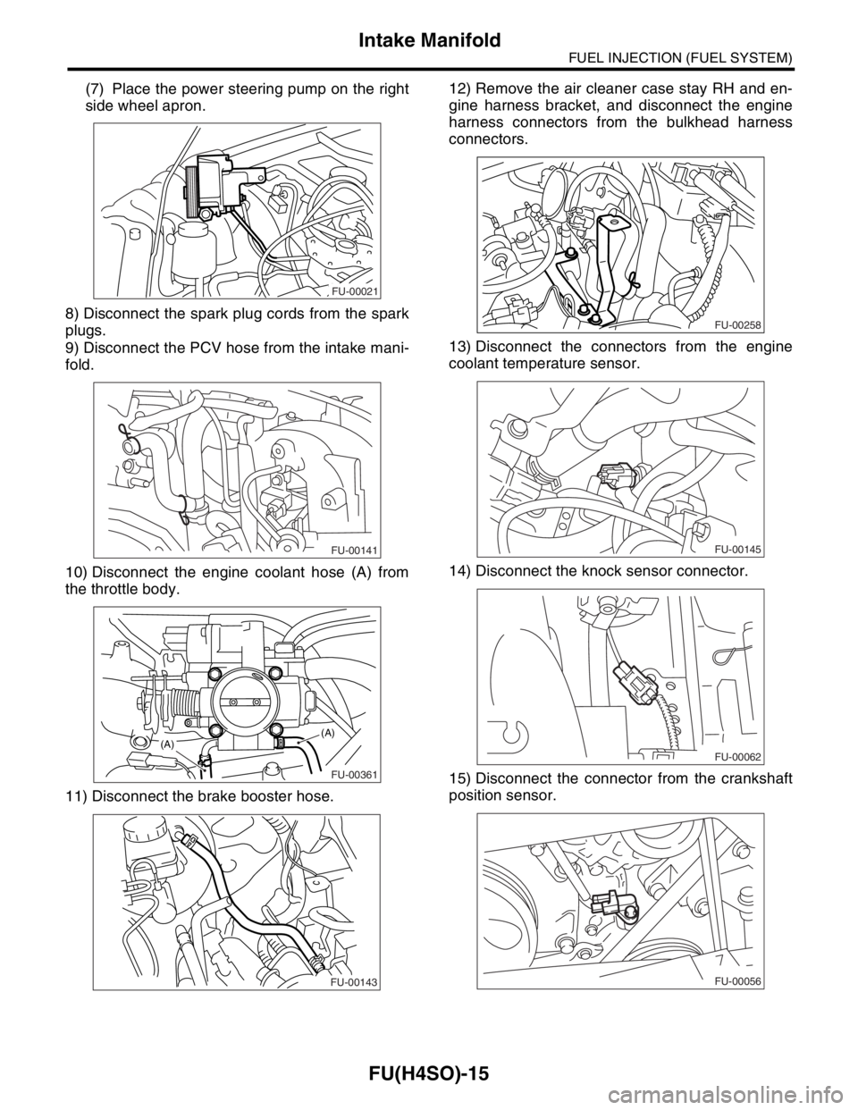
(7) Place the power steering pump on the right
side wheel apron.
8) Disconnect the spark plug cords from the spark
plugs.
9) Disconnect the PCV hose from the intake mani-
fold.
10) Disconnect the engine coolant hose (A) from
the throttle body.
11) Disconnect the brake booster hose.12) Remove the air cleaner case stay RH and en-
gine harness bracket, and disconnect the engine
harness connectors from the bulkhead harness
connectors.
13) Disconnect the connectors from the engine
coolant temperature sensor.
14) Disconnect the knock sensor connector.
15) Disconnect the connector from the crankshaft
position sensor.
FU-00021
FU-00141
FU-00361
(A)(A)
FU-00143
FU-00258
FU-00145
FU-00062
FU-00056
Page 818 of 2870
FU(H4SO)-36
FUEL INJECTION (FUEL SYSTEM)
Fuel Injector
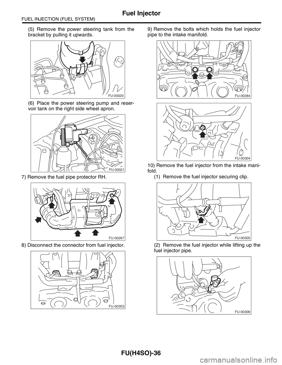
(5) Remove the power steering tank from the
bracket by pulling it upwards.
(6) Place the power steering pump and reser-
voir tank on the right side wheel apron.
7) Remove the fuel pipe protector RH.
8) Disconnect the connector from fuel injector.9) Remove the bolts which holds the fuel injector
pipe to the intake manifold.
10) Remove the fuel injector from the intake mani-
fold.
(1) Remove the fuel injector securing clip.
(2) Remove the fuel injector while lifting up the
fuel injector pipe.
FU-00020
FU-00021
FU-00267
FU-00303
FU-00284
FU-00304
FU-00305
FU-00306
Page 905 of 2870
ME(H4SO)-36
MECHANICAL
Engine Assembly
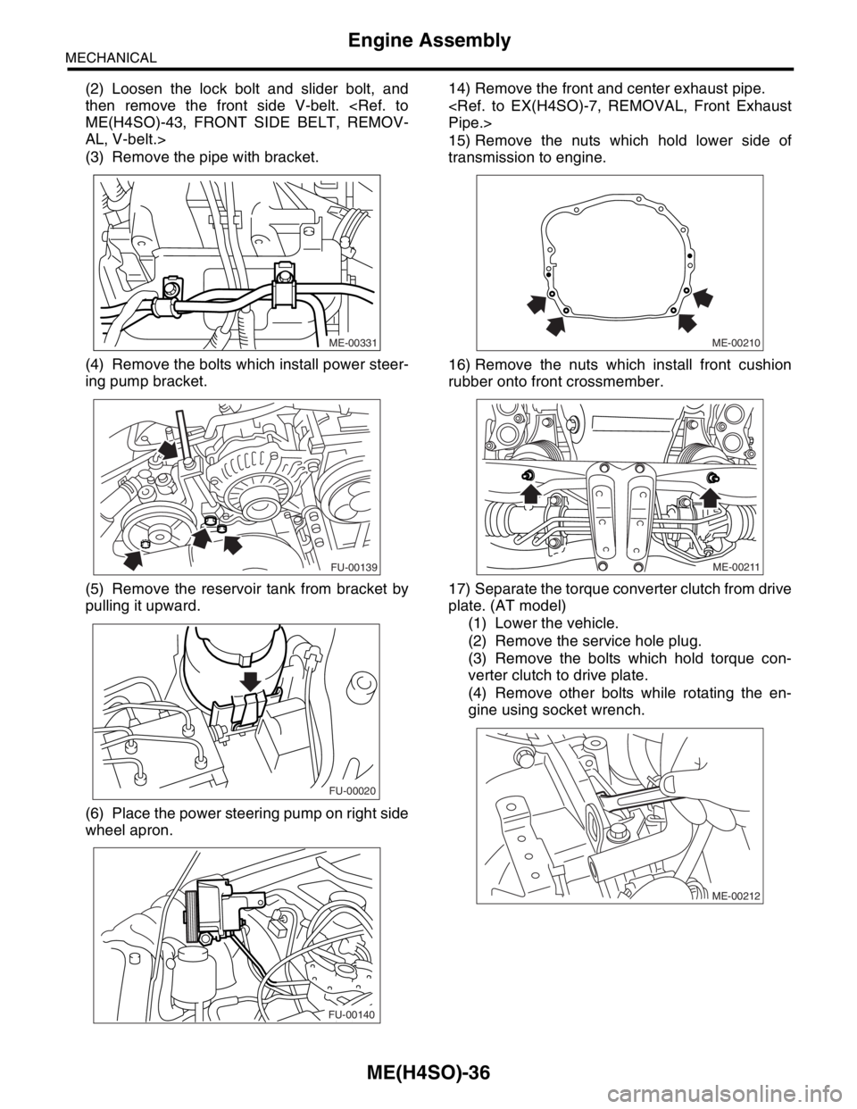
(2) Loosen the lock bolt and slider bolt, and
then remove the front side V-belt.
AL, V-belt.>
(3) Remove the pipe with bracket.
(4) Remove the bolts which install power steer-
ing pump bracket.
(5) Remove the reservoir tank from bracket by
pulling it upward.
(6) Place the power steering pump on right side
wheel apron.14) Remove the front and center exhaust pipe.
15) Remove the nuts which hold lower side of
transmission to engine.
16) Remove the nuts which install front cushion
rubber onto front crossmember.
17) Separate the torque converter clutch from drive
plate. (AT model)
(1) Lower the vehicle.
(2) Remove the service hole plug.
(3) Remove the bolts which hold torque con-
verter clutch to drive plate.
(4) Remove other bolts while rotating the en-
gine using socket wrench.
ME-00331
FU-00139
FU-00020
FU-00140ME-00210
ME-00211
ME-00212
Page 1370 of 2870
FU(H4DOTC)-15
FUEL INJECTION (FUEL SYSTEM)
Intake Manifold
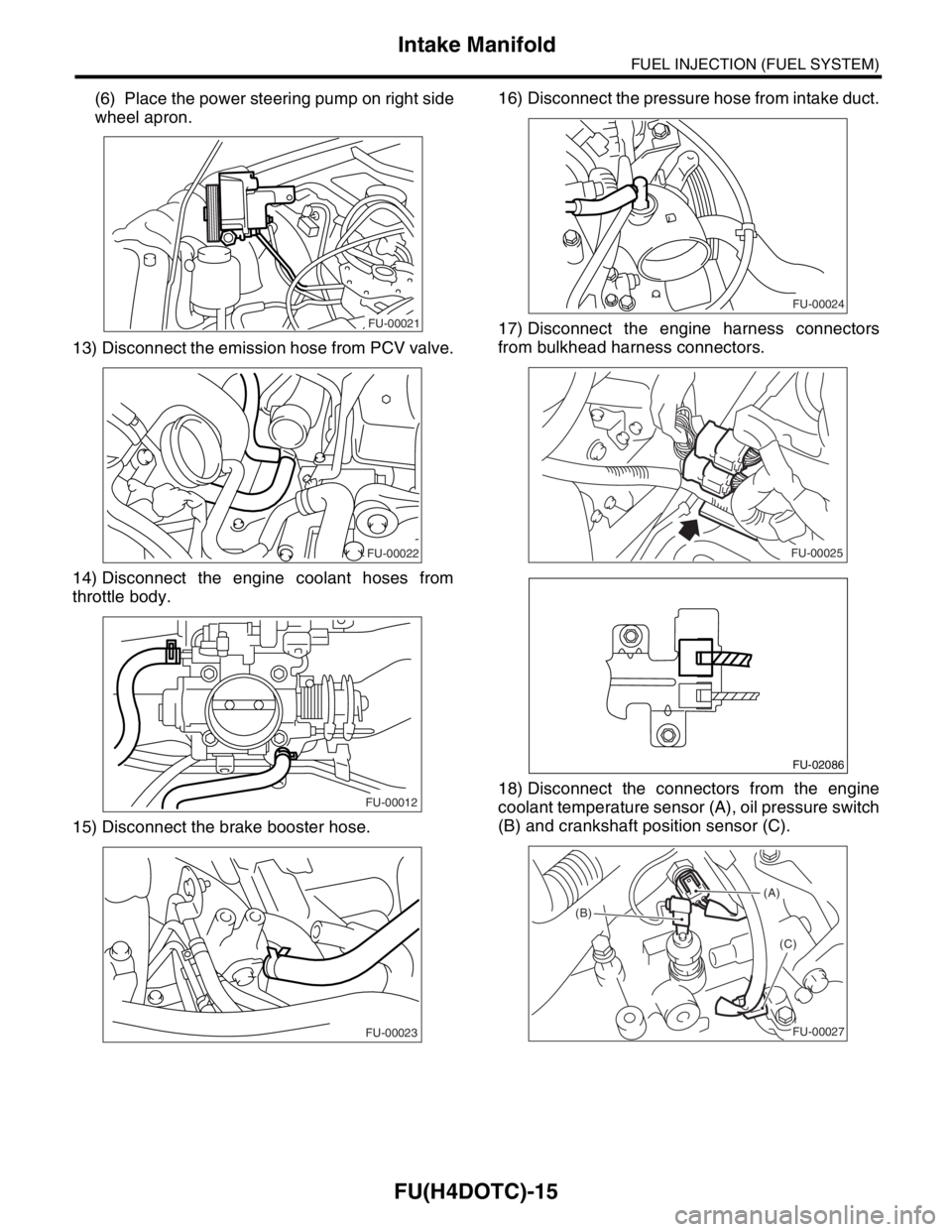
(6) Place the power steering pump on right side
wheel apron.
13) Disconnect the emission hose from PCV valve.
14) Disconnect the engine coolant hoses from
throttle body.
15) Disconnect the brake booster hose.16) Disconnect the pressure hose from intake duct.
17) Disconnect the engine harness connectors
from bulkhead harness connectors.
18) Disconnect the connectors from the engine
coolant temperature sensor (A), oil pressure switch
(B) and crankshaft position sensor (C).
FU-00021
FU-00022
FU-00012
FU-00023
FU-00024
FU-00025
FU-02086
(A)
(B)
(C)
FU-00027