2004 SUBARU FORESTER center console
[x] Cancel search: center consolePage 37 of 2870
AC-35
HVAC SYSTEM (HEATER, VENTILATOR AND A/C)
Control Unit
10.Control Unit
A: REMOVAL
1) Disconnect the ground cable from battery.
2) In case of manual A/C, remove the mode cable
and air-mix cable from links of heater unit.
3) Remove the console front cover.
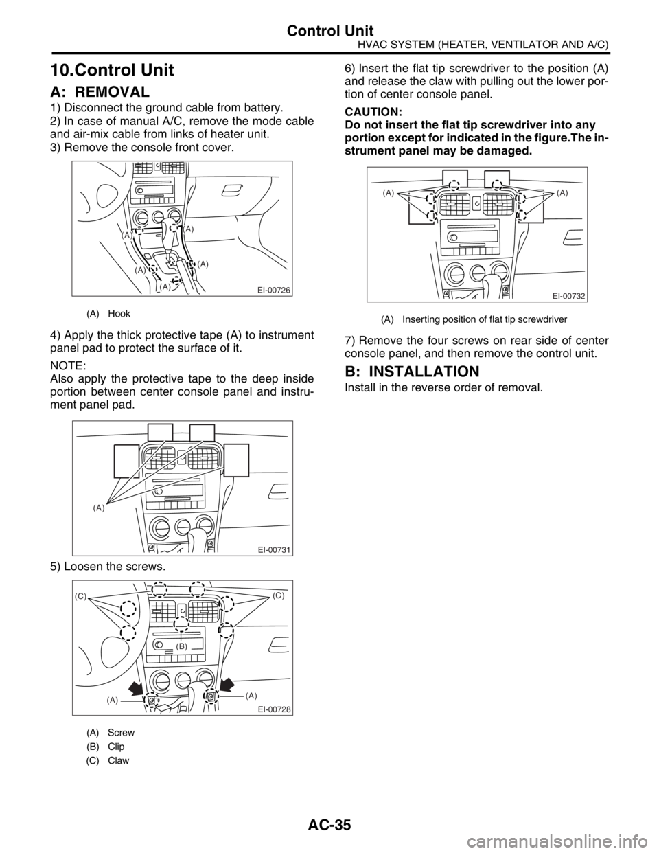
4) Apply the thick protective tape (A) to instrument
panel pad to protect the surface of it.
NOTE:
Also apply the protective tape to the deep inside
portion between center console panel and instru-
ment panel pad.
5) Loosen the screws.6) Insert the flat tip screwdriver to the position (A)
and release the claw with pulling out the lower por-
tion of center console panel.
CAUTION:
Do not insert the flat tip screwdriver into any
portion except for indicated in the figure.The in-
strument panel may be damaged.
7) Remove the four screws on rear side of center
console panel, and then remove the control unit.
B: INSTALLATION
Install in the reverse order of removal.
(A) Hook
(A) Screw
(B) Clip
(C) Claw
(A)
(A)
EI-00726
(A)
(A)
(A)
EI-00731
(A)
EI-00728
(C)
(A)(A)(C)
(B)
(A) Inserting position of flat tip screwdriver
EI-00732
(A) (A)
Page 48 of 2870
AC-46
HVAC SYSTEM (HEATER, VENTILATOR AND A/C)
Air Vent Grille
21.Air Vent Grille
A: REMOVAL
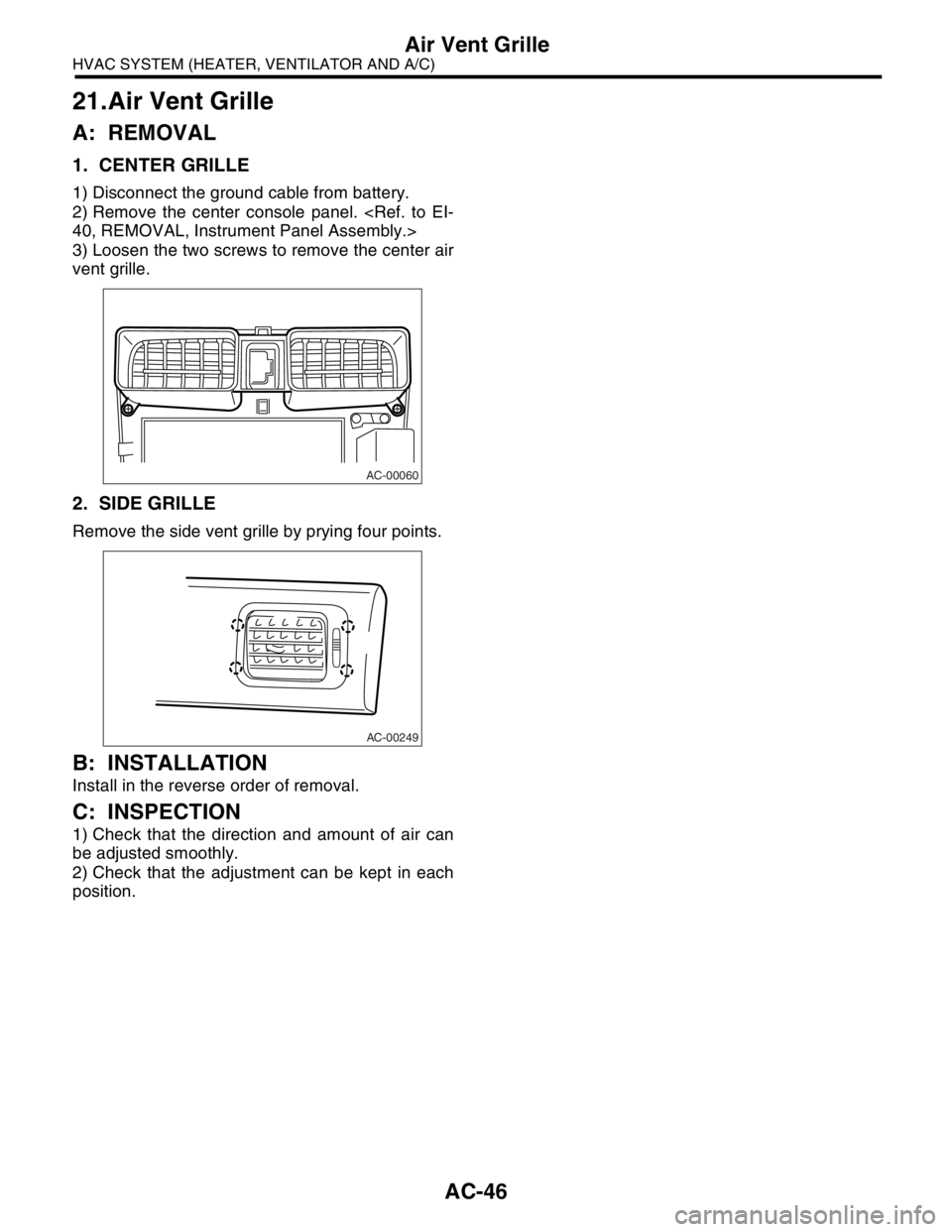
1. CENTER GRILLE
1) Disconnect the ground cable from battery.
2) Remove the center console panel.
3) Loosen the two screws to remove the center air
vent grille.
2. SIDE GRILLE
Remove the side vent grille by prying four points.
B: INSTALLATION
Install in the reverse order of removal.
C: INSPECTION
1) Check that the direction and amount of air can
be adjusted smoothly.
2) Check that the adjustment can be kept in each
position.
AC-00060
AC-00249
Page 118 of 2870
AB-18
AIRBAG SYSTEM
Airbag Control Module
7. Airbag Control Module
A: REMOVAL
CAUTION:
Do not disassemble the airbag control mod-
ule.
If the airbag control module is deformed or if
water damage is suspected, replace the airbag
control module with a new part.
Do not drop the airbag control module.
After removal, keep the airbag control mod-
ule on a dry, clean surface away from moisture,
heat, and dust.
1) Turn the ignition switch to OFF.
2) Disconnect the ground cable from battery, and
wait for at least 20 seconds before starting work.
3) Remove the console cover.
4) Remove the center console panel.
5) Disconnect the connector from airbag control
module.
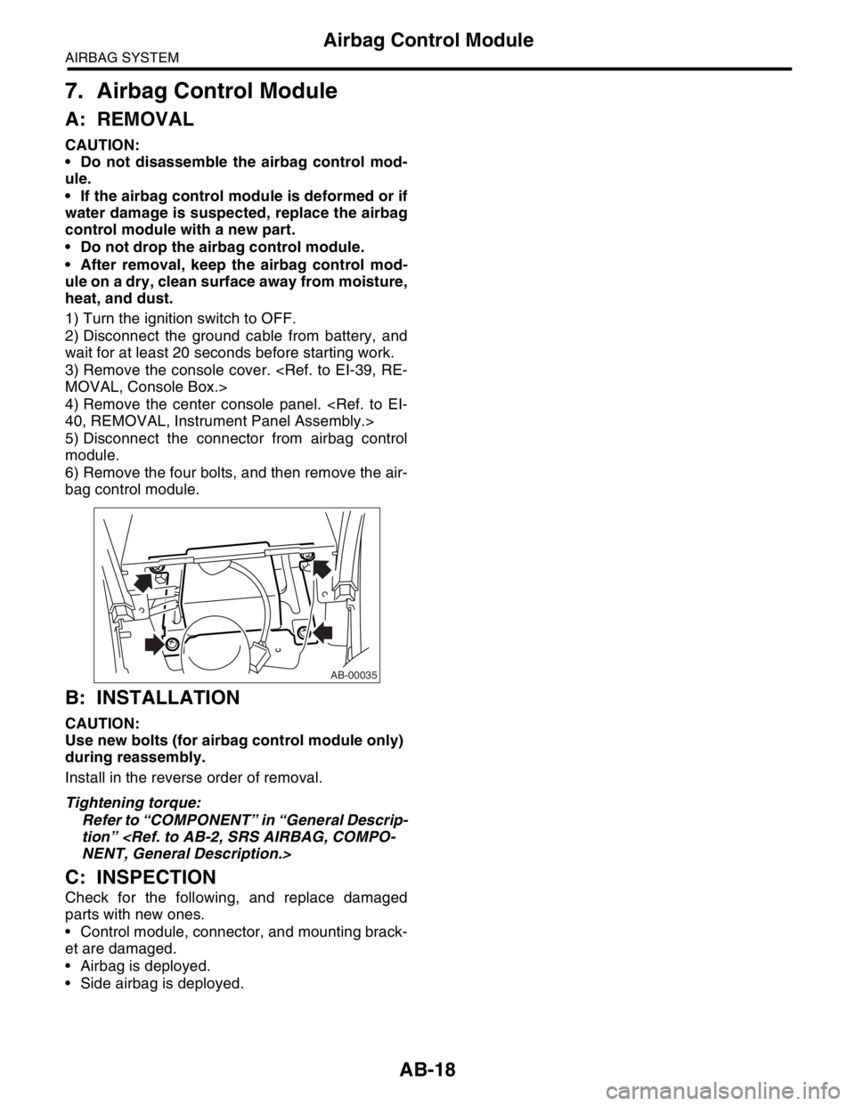
6) Remove the four bolts, and then remove the air-
bag control module.
B: INSTALLATION
CAUTION:
Use new bolts (for airbag control module only)
during reassembly.
Install in the reverse order of removal.
Tightening torque:
Refer to “COMPONENT” in “General Descrip-
tion”
C: INSPECTION
Check for the following, and replace damaged
parts with new ones.
Control module, connector, and mounting brack-
et are damaged.
Airbag is deployed.
Side airbag is deployed.
AB-00035
Page 315 of 2870
ET-5
ENTERTAINMENT
Radio Body
4. Radio Body
A: REMOVAL
1) Disconnect the ground cable from battery.
2) Remove the front cover.
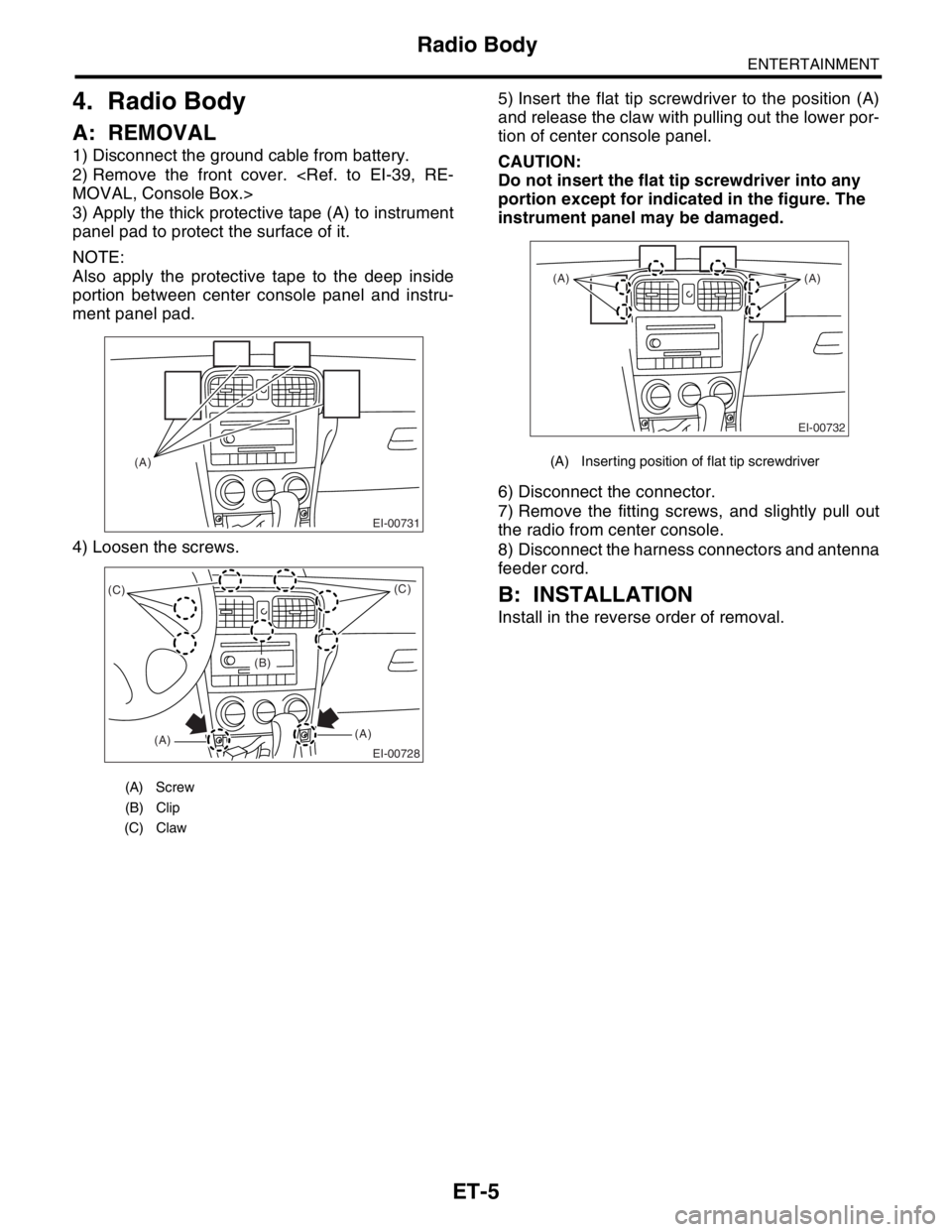
3) Apply the thick protective tape (A) to instrument
panel pad to protect the surface of it.
NOTE:
Also apply the protective tape to the deep inside
portion between center console panel and instru-
ment panel pad.
4) Loosen the screws.5) Insert the flat tip screwdriver to the position (A)
and release the claw with pulling out the lower por-
tion of center console panel.
CAUTION:
Do not insert the flat tip screwdriver into any
portion except for indicated in the figure. The
instrument panel may be damaged.
6) Disconnect the connector.
7) Remove the fitting screws, and slightly pull out
the radio from center console.
8) Disconnect the harness connectors and antenna
feeder cord.
B: INSTALLATION
Install in the reverse order of removal.
(A) Screw
(B) Clip
(C) Claw
EI-00731
(A)
EI-00728
(C)
(A)(A)(C)
(B)
(A) Inserting position of flat tip screwdriver
EI-00732
(A) (A)
Page 477 of 2870

EXTERIOR/INTERIOR TRIM
EI
Page
1. General Description ....................................................................................2
2. Front Grille ................................................................................................18
3. Hood Grille ................................................................................................19
4. Front Under Cover ....................................................................................22
5. Front Bumper ............................................................................................23
6. Rear Bumper .............................................................................................30
7. Mud Guard ................................................................................................31
8. Cowl Panel ................................................................................................32
9. Side Sill Spoiler .........................................................................................33
10. Side Garnish .............................................................................................34
11. Front Door Trim .........................................................................................35
12. Rear Door Trim .........................................................................................36
13. Glove Box..................................................................................................37
14. Roof Rail ...................................................................................................38
15. Console Box ..............................................................................................39
16. Instrument Panel Assembly ......................................................................40
17. Upper Inner Trim .......................................................................................43
18. Lower Inner Trim .......................................................................................44
19. Rear Quarter Trim .....................................................................................45
20. Sun Visor...................................................................................................46
21. Roof Trim ..................................................................................................47
22. Rear Gate Trim .........................................................................................48
23. Floor Mat ...................................................................................................49
24. Luggage Floor Mat ....................................................................................50
25. Instrument Panel Center Compartment ....................................................51
26. Heat Shield Cover .....................................................................................52
Page 516 of 2870
EI-40
EXTERIOR/INTERIOR TRIM
Instrument Panel Assembly
16.Instrument Panel Assembly
A: REMOVAL
CAUTION:
All airbag system wiring harness and connec-
tors are colored yellow. Do not use electrical test
equipment on these circuits.
Be careful not to damage the airbag system
harness when servicing the instrument panel.
1. REMOVAL OF INSTRUMENT PANEL
ONLY
1) Disconnect the ground cable from battery.
2) Loosen the screws and clips, and then remove
the lower cover.
3) Disconnect the in-vehicle sensor hose and con-
nector.
4) Remove the console front cover and console
cover.
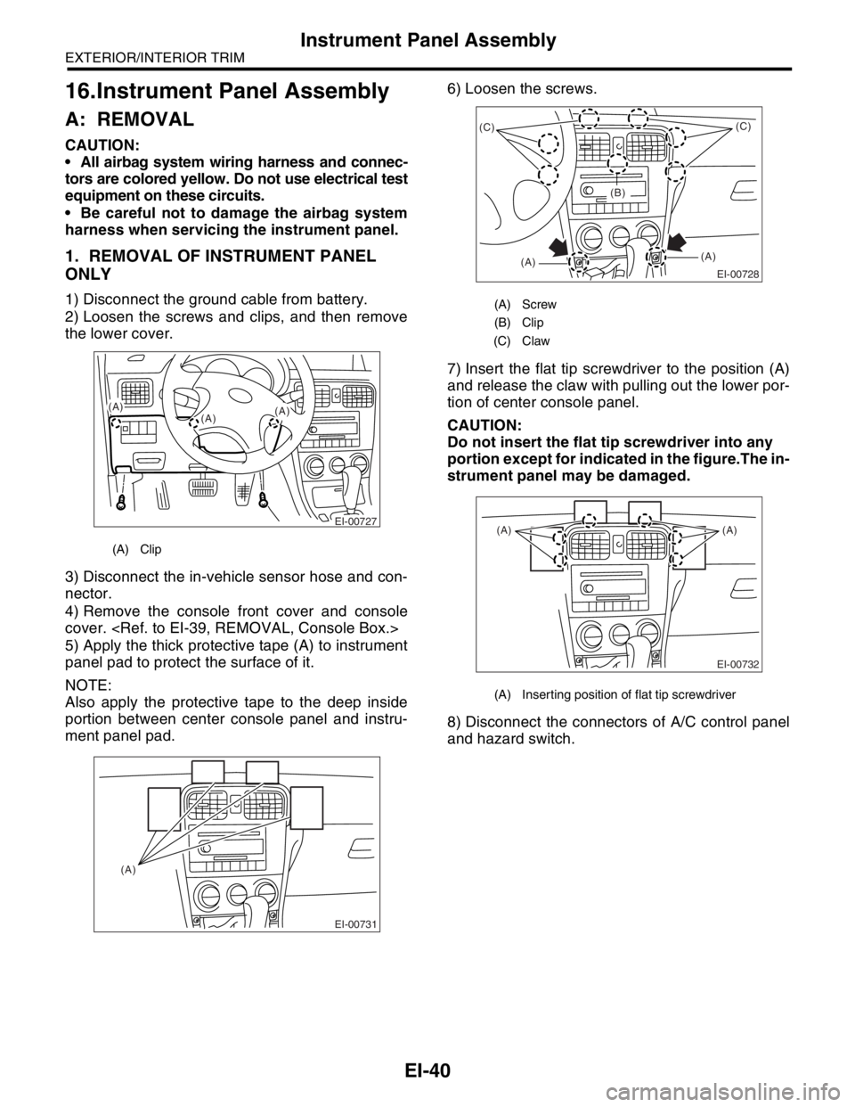
5) Apply the thick protective tape (A) to instrument
panel pad to protect the surface of it.
NOTE:
Also apply the protective tape to the deep inside
portion between center console panel and instru-
ment panel pad.6) Loosen the screws.
7) Insert the flat tip screwdriver to the position (A)
and release the claw with pulling out the lower por-
tion of center console panel.
CAUTION:
Do not insert the flat tip screwdriver into any
portion except for indicated in the figure.The in-
strument panel may be damaged.
8) Disconnect the connectors of A/C control panel
and hazard switch.
(A) Clip
EI-00727
(A)
(A)(A)
EI-00731
(A)
(A) Screw
(B) Clip
(C) Claw
(A) Inserting position of flat tip screwdriver
EI-00728
(C)
(A)(A)(C)
(B)
EI-00732
(A) (A)
Page 517 of 2870
EI-41
EXTERIOR/INTERIOR TRIM
Instrument Panel Assembly
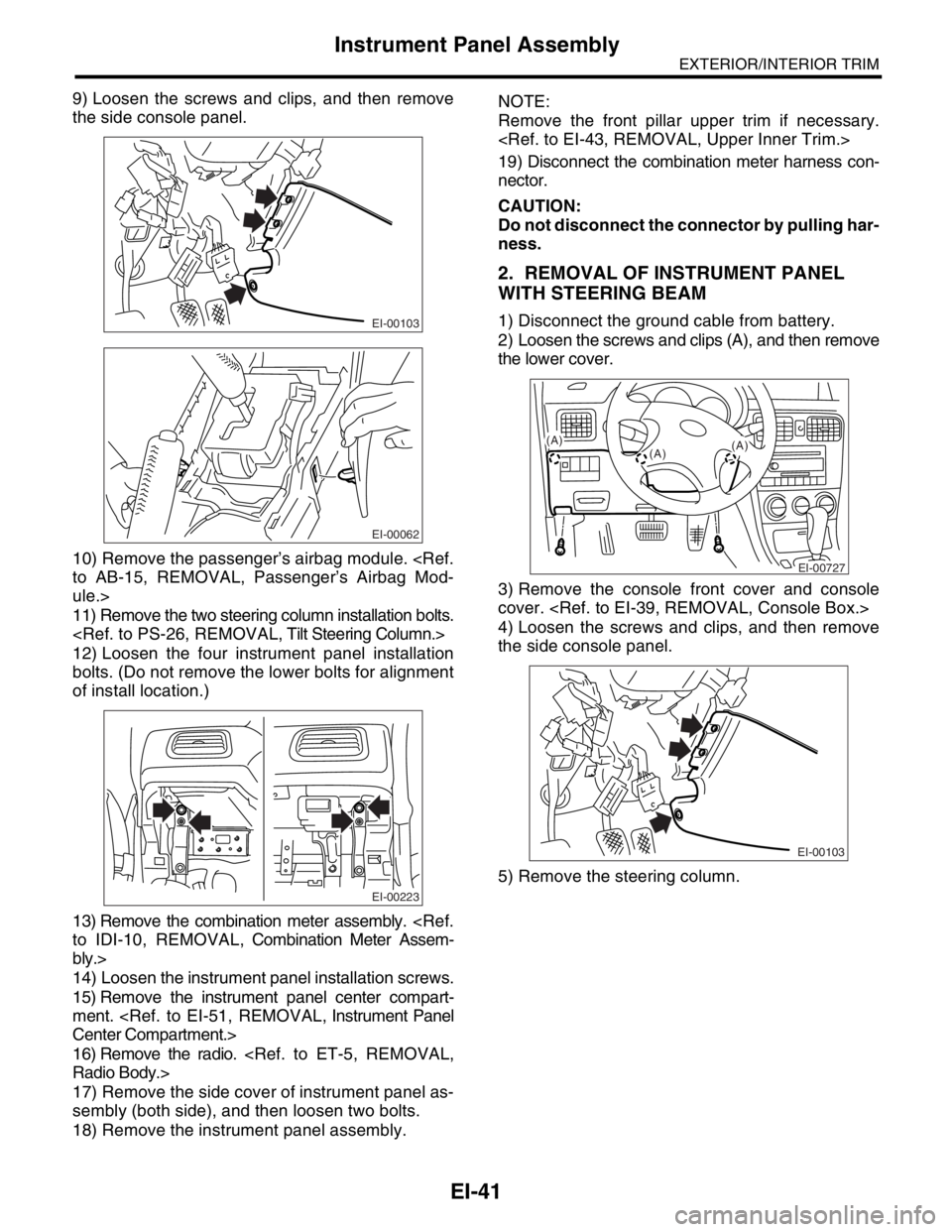
9) Loosen the screws and clips, and then remove
the side console panel.
10) Remove the passenger’s airbag module.
ule.>
11) Remove the two steering column installation bolts.
12) Loosen the four instrument panel installation
bolts. (Do not remove the lower bolts for alignment
of install location.)
13) Remove the combination meter assembly.
bly.>
14) Loosen the instrument panel installation screws.
15) Remove the instrument panel center compart-
ment.
16) Remove the radio.
17) Remove the side cover of instrument panel as-
sembly (both side), and then loosen two bolts.
18) Remove the instrument panel assembly.NOTE:
Remove the front pillar upper trim if necessary.
19) Disconnect the combination meter harness con-
nector.
CAUTION:
Do not disconnect the connector by pulling har-
ness.
2. REMOVAL OF INSTRUMENT PANEL
WITH STEERING BEAM
1) Disconnect the ground cable from battery.
2) Loosen the screws and clips (A), and then remove
the lower cover.
3) Remove the console front cover and console
cover.
4) Loosen the screws and clips, and then remove
the side console panel.
5) Remove the steering column.EI-00103
EI-00062
EI-00223
EI-00727
(A)
(A)(A)
EI-00103
Page 525 of 2870
EI-49
EXTERIOR/INTERIOR TRIM
Floor Mat
23.Floor Mat
A: REMOVAL
1) Remove the front seats.
2) Remove the rear seat cushion.
3) Remove the console box.
4) Remove the side sill front cover, side sill rear
cover and center pillar lower trim.
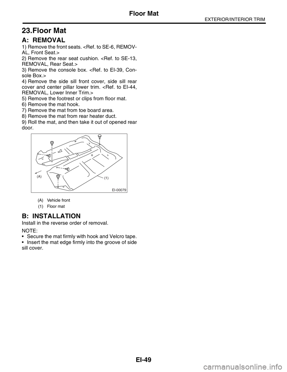
5) Remove the footrest or clips from floor mat.
6) Remove the mat hook.
7) Remove the mat from toe board area.
8) Remove the mat from rear heater duct.
9) Roll the mat, and then take it out of opened rear
door.
B: INSTALLATION
Install in the reverse order of removal.
NOTE:
Secure the mat firmly with hook and Velcro tape.
Insert the mat edge firmly into the groove of side
sill cover.
(A) Vehicle front
(1) Floor mat
EI-00079
(A)(1)