Page 311 of 2870
ENTERTAINMENT
ET
Page
1. General Description ....................................................................................2
2. Radio System ..............................................................................................3
3. Front Accessory Power Supply Socket System ..........................................4
4. Radio Body..................................................................................................5
5. Front Speaker .............................................................................................6
6. Antenna .......................................................................................................7
7. Antenna Amplifier ........................................................................................8
8. Front Accessory Power Supply Socket .......................................................9
Page 312 of 2870
ET-2
ENTERTAINMENT
General Description
1. General Description
A: CAUTION
Before disassembling or reassembling parts, al-
ways disconnect the battery ground cable. When re-
placing radio, control module and other parts
provided with memory functions, record memory con-
tents before disconnecting the battery ground cable.
Otherwise, the memory will be erased.
Reassemble in reverse order of disassembly, un-
less otherwise indicated.
Adjust parts to the given specifications.
Connect the connectors and hoses securely dur-
ing reassembly.
After reassembly, make sure functional parts op-
erate smoothly.
B: PREPARATION TOOL
1. GENERAL TOOL
TOOL NAME REMARKS
Circuit tester Used for measuring resis-
tance and voltage.
Conductive silver composi-
tion
(DUPONT No. 4817 or
equivalent)Used for repairing antenna
wire.
Page 313 of 2870
ET-3
ENTERTAINMENT
Radio System
2. Radio System
A: WIRING DIAGRAM
1. RADIO
B: INSPECTION
Symptom Repair order
No power coming in. (No display and no sound from speakers.) (1) Check the fuse and power supply for radio.
(2) Check the radio ground.
(3) Remove the radio for repair.
A specific speaker does not operate. (1) Check the speaker.
(2) Check the output circuit between radio and speaker.
Radio generates noise with engine running. (1) Check the radio ground.
(2) Check the generator.
(3) Check the ignition coil.
(4) Remove the radio for repair.
AM and FM modes are weak or noisy. (1) Check the antenna.
(2) Check the antenna amplifier.
(3) Check the noise suppressor.
(4) Check the radio ground.
(5) Remove the radio for repair.
Page 315 of 2870

ET-5
ENTERTAINMENT
Radio Body
4. Radio Body
A: REMOVAL
1) Disconnect the ground cable from battery.
2) Remove the front cover.
MOVAL, Console Box.>
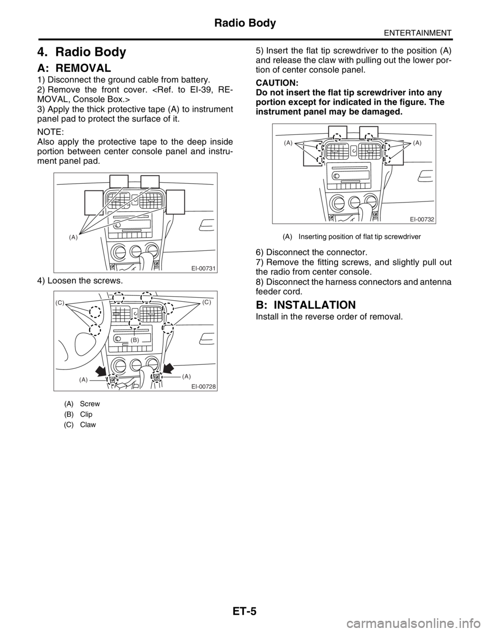
3) Apply the thick protective tape (A) to instrument
panel pad to protect the surface of it.
NOTE:
Also apply the protective tape to the deep inside
portion between center console panel and instru-
ment panel pad.
4) Loosen the screws.5) Insert the flat tip screwdriver to the position (A)
and release the claw with pulling out the lower por-
tion of center console panel.
CAUTION:
Do not insert the flat tip screwdriver into any
portion except for indicated in the figure. The
instrument panel may be damaged.
6) Disconnect the connector.
7) Remove the fitting screws, and slightly pull out
the radio from center console.
8) Disconnect the harness connectors and antenna
feeder cord.
B: INSTALLATION
Install in the reverse order of removal.
(A) Screw
(B) Clip
(C) Claw
EI-00731
(A)
EI-00728
(C)
(A)(A)(C)
(B)
(A) Inserting position of flat tip screwdriver
EI-00732
(A) (A)
Page 324 of 2870
COM-2
COMMUNICATION SYSTEM
General Description
1. General Description
A: CAUTION
Before disassembling or reassembling parts, al-
ways disconnect the battery ground cable. When re-
placing radio, control module and other parts
provided with memory functions, record memory con-
tents before disconnecting the battery ground cable.
Otherwise, the memory will be erased.
Reassemble in reverse order of disassembly, un-
less otherwise indicated.
Adjust parts to the given specifications.
Connect the connectors and hoses securely dur-
ing reassembly.
After reassembly, make sure functional parts op-
erate smoothly.
B: PREPARATION TOOL
1. GENERAL TOOL
TO OL
NAMEREMARKS
Circuit
testerUsed for measuring resistance and voltage.
Page 427 of 2870

SL-7
SECURITY AND LOCK
General Description
5. KEYLESS ENTRY SYSTEM
B: CAUTION
Before disassembling or reassembling parts,
always disconnect the ground cable from battery.
When repairing radio, control module, etc. which
are provided with memory functions, record the
memory contents before disconnecting the
ground cable from battery. Otherwise, these
contents are cancelled upon disconnection.
Reassemble parts in the reverse order of
disassembly procedure unless otherwise
indicated.
Adjust parts to specifications contained in
this manual if so designated.
Connect the connectors and hoses securely
during reassembly.
After reassembly, ensure all functional parts
operate smoothly.
Airbag system wiring harness is routed near
the electrical parts and switch.
All airbag system wiring harness and
connectors are colored yellow. Do not use
electrical test equipment on these circuits. Be careful not to damage the airbag system
wiring harness when servicing the ignition key
cylinder.
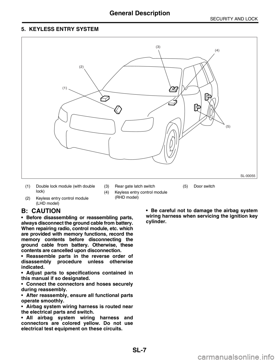
(1) Double lock module (with double
lock)(3) Rear gate latch switch (5) Door switch
(4) Keyless entry control module
(RHD model)
(2) Keyless entry control module
(LHD model)
SL-00055
(2)
(5)
(4)(3)
(1)
Page 517 of 2870

EI-41
EXTERIOR/INTERIOR TRIM
Instrument Panel Assembly
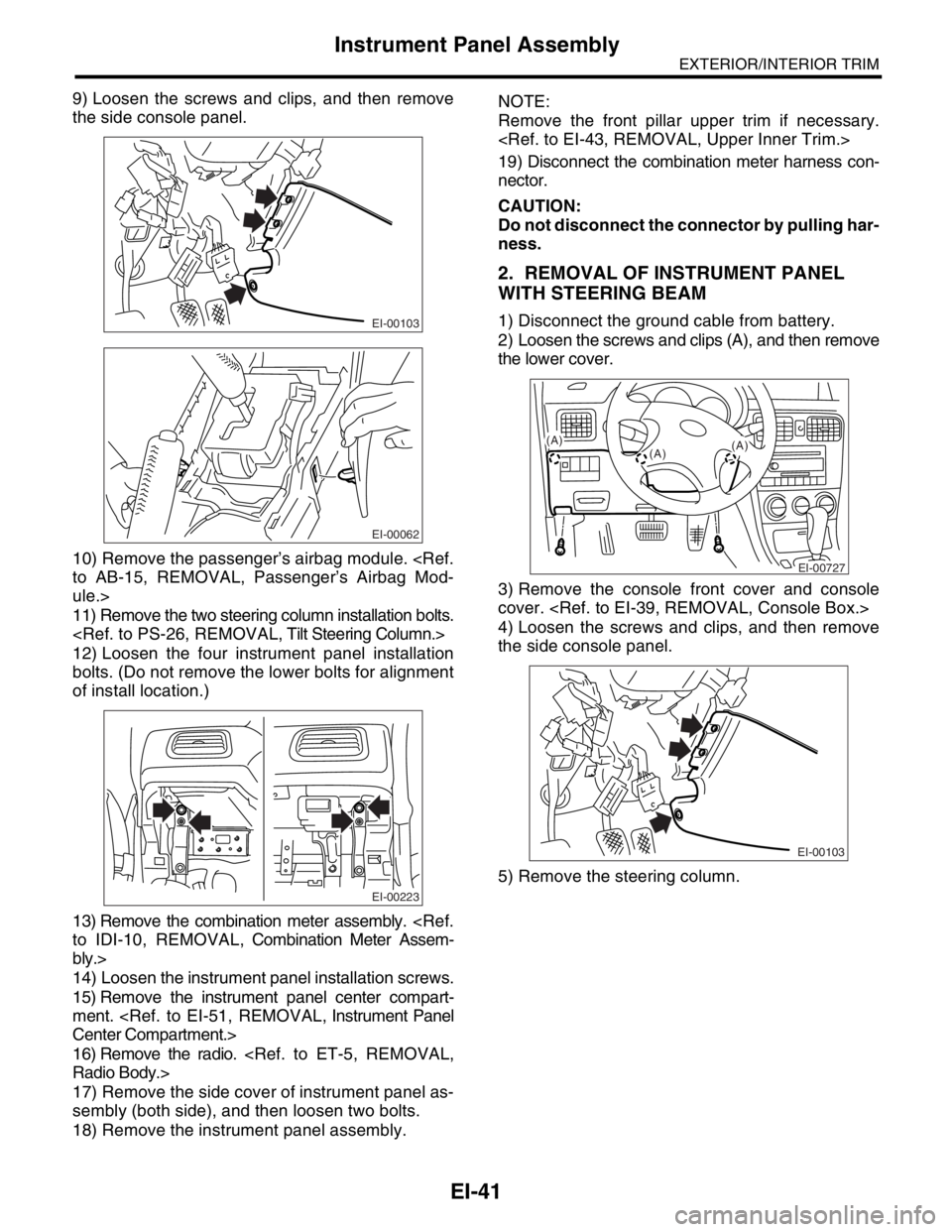
9) Loosen the screws and clips, and then remove
the side console panel.
10) Remove the passenger’s airbag module.
to AB-15, REMOVAL, Passenger’s Airbag Mod-
ule.>
11) Remove the two steering column installation bolts.
12) Loosen the four instrument panel installation
bolts. (Do not remove the lower bolts for alignment
of install location.)
13) Remove the combination meter assembly.
to IDI-10, REMOVAL, Combination Meter Assem-
bly.>
14) Loosen the instrument panel installation screws.
15) Remove the instrument panel center compart-
ment.
Center Compartment.>
16) Remove the radio.
Radio Body.>
17) Remove the side cover of instrument panel as-
sembly (both side), and then loosen two bolts.
18) Remove the instrument panel assembly.NOTE:
Remove the front pillar upper trim if necessary.
19) Disconnect the combination meter harness con-
nector.
CAUTION:
Do not disconnect the connector by pulling har-
ness.
2. REMOVAL OF INSTRUMENT PANEL
WITH STEERING BEAM
1) Disconnect the ground cable from battery.
2) Loosen the screws and clips (A), and then remove
the lower cover.
3) Remove the console front cover and console
cover.
4) Loosen the screws and clips, and then remove
the side console panel.
5) Remove the steering column.EI-00103
EI-00062
EI-00223
EI-00727
(A)
(A)(A)
EI-00103
Page 556 of 2870
CC-4
CRUISE CONTROL SYSTEM
General Description
B: CAUTION
Before disassembling or reassembling parts, al-
ways disconnect the battery ground cable. When re-
pairing the radio, control module and other parts with
memory functions, make note of the memory before
disconnecting the battery ground cable. All memory
will be erased.
Reassemble parts in the reverse order of disas-
sembly unless otherwise indicated.
Adjust parts to specifications specified in this man-
ual.
Connect the connectors and hoses securely dur-
ing reassembly.
After reassembly, ensure functional parts operate
properly.
C: PREPARATION TOOL
TOOL NAME REMARKS
Circuit Tester Used for measuring resis-
tance and voltage.