Page 693 of 2870

SPC-4
SPECIFICATION
Forester
F: SUSPENSION
G: BRAKE
★: RHD model
H: TIRE
I: CAPACITY
★1: With oil pump★2: MT model with oil cooler Included★3: Model with ATF warmer Front Macpherson strut type, Independent, Coil spring
Rear Dual-link type, Independent, Coil spring
Model 2.0 L Non-turbo, 2.5 L Non-turbo
2.0 L Turbo, 2.5 L Non-turbo
★, 2.5 L Non-turbo
Service brake system Dual circuit hydraulic with vacuum suspended power unit
Front Ventilated disc brake
Rear Drum brake Disc brake
Parking brake Mechanical on rear brakes
Rim size 15×6J 16×6 1/2J
Tire size 205/70 R15 95H 215/60 R16 95V, P215/60 R16 94H
Type Steel belted radial, Tubeless
Model 2.0 L Non-turbo 2.0 L Turbo 2.5 L Non-turbo 2.5 L Turbo
Tr a n s m i s s i o n 5 M T 4 AT 5 M T 4 AT 5 M T 4 AT 5 M T 4 AT
Fuel tank2 (US gal, Imp gal) 60 (15.9, 13.2)
Engine oil
(When
replacing)2 (US qt, Imp qt) Approx. 4.0 (4.2, 3.5)
Tr a n s m i s -
sion gear oil2 (US qt, Imp qt)4.0
(4.2, 3.5)—3.5
(3.7, 3.1),
3.9
(4.1, 3.4)
★1
—4.0
(4.2, 3.5)—3.5
(3.7, 3.1)—
AT F2 (US qt, Imp qt) —8.4
(8.9, 7.4)—9.3
(9.8, 8.2)—9.3
(9.8, 8.2)—9.3
(9.8, 8.2)
Front differ-
ential gear
oil2 (US qt, Imp qt) —1.2
(1.3, 1.1)—1.2
(1.3, 1.1)—1.2
(1.3, 1.1)—1.2
(1.3, 1.1)
Rear differ-
ential gear
oil2 (US qt, Imp qt) 0.8 (0.8, 0.6)
Pow er
steering
fluid2 (US qt, Imp qt) 0.7 (0.7, 0.6)
Engine
coolant2 (US qt, Imp qt)6.6
(7.0, 5.8)6.5
(6.9, 5.7),
6.9
(7.3, 6.1)
★3
7.4
(7.8, 6.5)7.3
(7.7, 6.4)
★2
6.9
(7.3, 6.1)6.8
(7.2, 6.0)7.4
(7.8, 6.5)7.3
(7.7, 6.4)
Page 730 of 2870
PI-7
PRE-DELIVERY INSPECTION
Pre-delivery Inspection
8. CHECK THE REAR GATE FOR LOCK/
UNLOCK AND OPEN/CLOSE OPERA-
TIONS.
1) Open and close the rear gate several times for
smooth movement.
2) Operate the rear gate lever to check that the rear
gate is locked and unlocked normally.
(1) Remove the blind cover inside the rear gate.
(2) Using a screwdriver, check the rear gate is
lock/unlock.
9. OPERATION CHECK OF FUEL LID
OPENER LOCK RELEASE LEVER
Operate the fuel lid opener and verify that the fuel
lid opens normally. Check that the filler cap is se-
curely closed.
10.ACCESSORY CHECK
Check that the following accessories are provided
in the luggage compartment or cargo area.
Owner’s manual
Warranty booklet
Service booklet
Spare key
Jack
Tool set
Spare tire
PI-00006
PI-00007
(A) Jack
(A) Jack handle
PI-00008
(A)
PI-00009(A)
Page 784 of 2870
FU(H4SO)-2
FUEL INJECTION (FUEL SYSTEM)
General Description
1. General Description
A: SPECIFICATION
ModelSpecification
Fuel tankCapacity 602 (15.9 US gal, 13.2 Imp gal)
Location Under rear seat
Fuel pumpType Impeller
Shutoff discharge pressure
370 — 677 kPa (3.77 — 6.9 kg/cm
2, 53.6 — 98 psi)
Discharge flowMore than 652 (17.2 US gal, 14.3 Imp gal) /h
[12 V at 300 kPa (3.06 kg/cm
2, 43.5 psi)]
Fuel filterCartridge type
Page 793 of 2870
FU(H4SO)-11
FUEL INJECTION (FUEL SYSTEM)
General Description
6. FUEL FILLER PIPE
(1) Fuel filler pipe ASSY (6) Air vent pipe (11) Fuel filler cap tether
(2) Evaporation hose holder (7) Air vent pipe holder (12) Fuel filler pipe protector
(3) Clip (8) Fuel filler pipe packing
(4) Clamp (9) Fuel filler ringTightening torque: N
⋅m (kgf-m, ft-lb)
(5) Air vent hose (10) Fuel filler capT: 7.5 (0.76, 5.5)
FU-00006
(4)
(2)
(8)
(1)
(12)(11)
(6)
(7)
(9)
(10)
(5)
(3)
(3)
T
T
T
T
T
Page 794 of 2870

FU(H4SO)-12
FUEL INJECTION (FUEL SYSTEM)
General Description
C: CAUTION
Wear working clothing, including a cap, protec-
tive goggles, and protective shoes during opera-
tion.
Remove contamination including dirt and corro-
sion before removal, installation or disassembly.
Keep the disassembled parts in order and pro-
tect them from dust or dirt.
Before removal, installation or disassembly, be
sure to clarify the failure. Avoid unnecessary re-
moval, installation, disassembly, and replacement. Be careful not to burn yourself, because each
part on the vehicle is hot after running.
Be sure to tighten fasteners including bolts and
nuts to the specified torque.
Place shop jacks or rigid racks at the specified
points.
Before disconnecting electrical connectors of
sensors or units, be sure to disconnect negative
terminal from battery.
Place “NO FIRE” signs near the working area.
Be careful not to spill fuel on the floor.
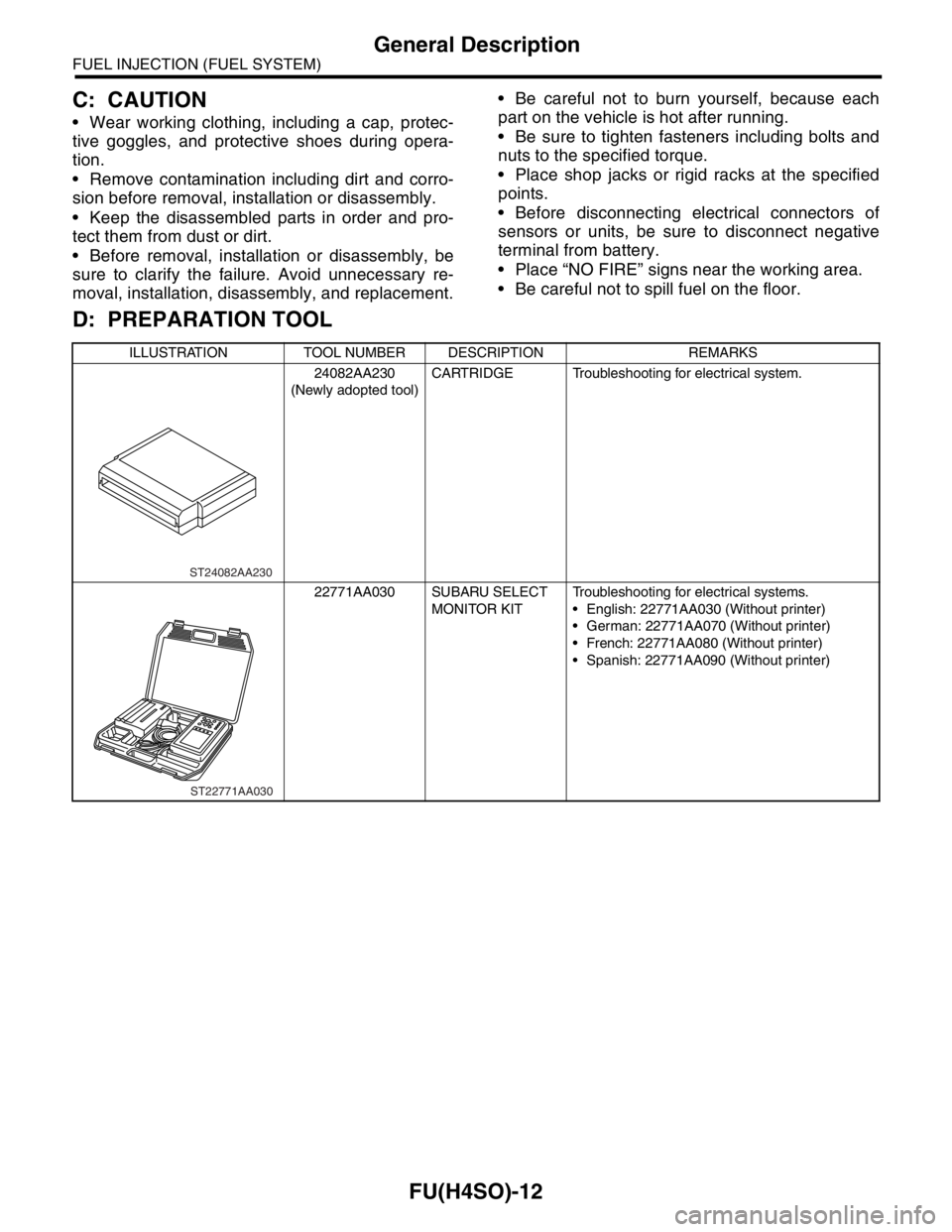
D: PREPARATION TOOL
ILLUSTRATION TOOL NUMBER DESCRIPTION REMARKS
24082AA230
(Newly adopted tool)CARTRIDGE Troubleshooting for electrical system.
22771AA030 SUBARU SELECT
MONITOR KITTroubleshooting for electrical systems.
English: 22771AA030 (Without printer)
German: 22771AA070 (Without printer)
French: 22771AA080 (Without printer)
Spanish: 22771AA090 (Without printer)
ST24082AA230
ST22771AA030
Page 796 of 2870

FU(H4SO)-14
FUEL INJECTION (FUEL SYSTEM)
Intake Manifold
3. Intake Manifold
A: REMOVAL
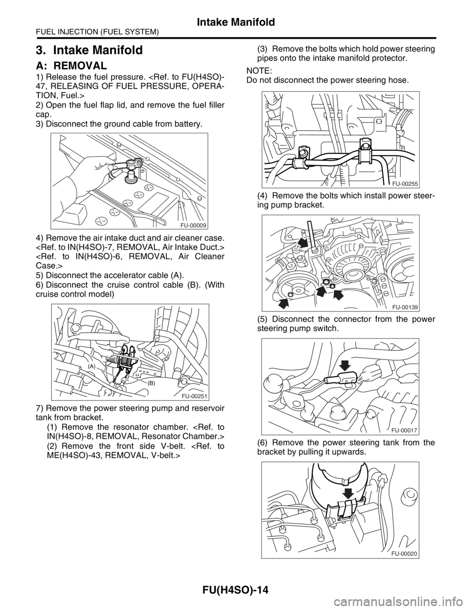
1) Release the fuel pressure.
47, RELEASING OF FUEL PRESSURE, OPERA-
TION, Fuel.>
2) Open the fuel flap lid, and remove the fuel filler
cap.
3) Disconnect the ground cable from battery.
4) Remove the air intake duct and air cleaner case.
Case.>
5) Disconnect the accelerator cable (A).
6) Disconnect the cruise control cable (B). (With
cruise control model)
7) Remove the power steering pump and reservoir
tank from bracket.
(1) Remove the resonator chamber.
IN(H4SO)-8, REMOVAL, Resonator Chamber.>
(2) Remove the front side V-belt.
ME(H4SO)-43, REMOVAL, V-belt.>(3) Remove the bolts which hold power steering
pipes onto the intake manifold protector.
NOTE:
Do not disconnect the power steering hose.
(4) Remove the bolts which install power steer-
ing pump bracket.
(5) Disconnect the connector from the power
steering pump switch.
(6) Remove the power steering tank from the
bracket by pulling it upwards.
FU-00009
FU-00251
(B)
(A)
FU-00255
FU-00139
FU-00017
FU-00020
Page 809 of 2870
FU(H4SO)-27
FUEL INJECTION (FUEL SYSTEM)
Camshaft Position Sensor
6. Camshaft Position Sensor
A: REMOVAL
1) Disconnect the ground cable from battery.
2) Disconnect the connector from the camshaft po-
sition sensor.
3) Remove the bolt which installs camshaft position
sensor to the camshaft position sensor support.
4) Remove the bolt which installs camshaft position
sensor support to the camshaft cap LH.
5) Remove the camshaft position sensor and cam-
shaft position sensor support as a unit.6) Remove the camshaft position sensor itself.
B: INSTALLATION
Install in the reverse order of removal.
Tightening torque:
Camshaft position sensor support;
6.4 N
⋅m (0.65 kgf-m, 4.7 ft-lb)
Camshaft position sensor;
6.4 N
⋅m (0.65 kgf-m, 4.7 ft-lb)
FU-00009
FU-00147
FU-00177
FU-00178
FU-00179
Page 817 of 2870
FU(H4SO)-35
FUEL INJECTION (FUEL SYSTEM)
Fuel Injector
13.Fuel Injector
A: REMOVAL
1. RH SIDE
1) Release the fuel pressure.
PRESSURE, OPERATION, Fuel.>
2) Open the fuel flap lid, and remove the fuel filler
cap.
3) Disconnect the ground cable from battery.
4) Remove the resonator chamber.
IN(H4SO)-8, REMOVAL, Resonator Chamber.>
5) Remove the spark plug cords from the spark
plugs (#1 and #3 cylinders).6) Remove the power steering pump and reservoir
tank from the brackets.
(1) Remove the front side V-belt.
ME(H4SO)-43, REMOVAL, V-belt.>
(2) Remove the bolts which hold the power
steering pipes onto the intake manifold protec-
tor.
(3) Remove the bolts which install the power
steering pump to the bracket.
(4) Disconnect the connector from the power
steering pump switch.
FU-00009
FU-00302
FU-00255
FU-00139
FU-00017