2004 SUBARU FORESTER fuel cap
[x] Cancel search: fuel capPage 1499 of 2870

ME(H4DOTC)-41
MECHANICAL
Engine Assembly
9. Engine Assembly
A: REMOVAL
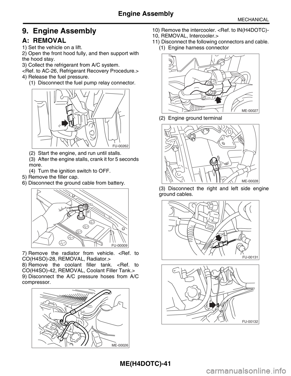
1) Set the vehicle on a lift.
2) Open the front hood fully, and then support with
the hood stay.
3) Collect the refrigerant from A/C system.
4) Release the fuel pressure.
(1) Disconnect the fuel pump relay connector.
(2) Start the engine, and run until stalls.
(3) After the engine stalls, crank it for 5 seconds
more.
(4) Turn the ignition switch to OFF.
5) Remove the filler cap.
6) Disconnect the ground cable from battery.
7) Remove the radiator from vehicle.
8) Remove the coolant filler tank.
9) Disconnect the A/C pressure hoses from A/C
compressor.10) Remove the intercooler.
11) Disconnect the following connectors and cable.
(1) Engine harness connector
(2) Engine ground terminal
(3) Disconnect the right and left side engine
ground cables.
FU-00262
FU-00009
ME-00026
ME-00027
ME-00028
FU-00131
FU-00132
Page 1579 of 2870

ME(H4DOTC)-119
MECHANICAL
Engine Trouble in General
4) Engine stalls after initial
combustion. Engine control system
Intake system Loosened or cracked intake duct B
Loosened or cracked PCV hose C
Loosened or cracked vacuum hose C
Defective intake manifold gasket B
Defective throttle body gasket B
Dirty air cleaner element C
Fuel line Clogged fuel line C
Lack of or insufficient fuel B
Belt Defective (deterioration, etc.) B
Defective timing B
Compression Incorrect valve clearance C
Loosened spark plugs or defective gasket C
Loosened cylinder head bolts or defective gasket C
Improper valve seating C
Defective valve stem C
Worn or broken valve spring B
Worn or stuck piston rings, cylinder and piston C
Incorrect valve timing B
Improper engine oil (low viscosity) B
2. Rough idle and engine
stallEngine control system
Intake system Loosened or cracked intake duct A
Loosened or cracked PCV hose A
Loosened or cracked vacuum hose A
Defective intake manifold gasket B
Defective throttle body gasket B
Defective PCV valve C
Loosened oil filler cap B
Dirty air cleaner element C
Fuel line Defective fuel pump and relay C
Clogged fuel line C
Lack of or insufficient fuel B
Belt Defective timing C
Compression Incorrect valve clearance B
Loosened spark plugs or defective gasket B
Loosened cylinder head bolts or defective gasket B
Improper valve seating B
Defective valve stem C
Worn or broken valve spring B
Worn or stuck piston rings, cylinder and piston B
Incorrect valve timing A
Improper engine oil (low viscosity) B
Lubrication system Incorrect oil pressure B
Defective rocker cover gasket C
Cooling system Overheating C
Others Malfunction of evaporative emission control system A
Stuck or damaged throttle valve B
Accelerator cable out of adjustment C TROUBLE PROBLEM PARTS, ETC. POSSIBLE CAUSE RANK
Page 1580 of 2870

ME(H4DOTC)-120
MECHANICAL
Engine Trouble in General
3. Low output, hesitation and
poor accelerationEngine control system
Intake system Loosened or cracked intake duct A
Loosened or cracked PCV hose A
Loosened or cracked vacuum hose B
Defective intake manifold gasket B
Defective throttle body gasket B
Defective PCV valve B
Loosened oil filler cap B
Dirty air cleaner element A
Fuel line Defective fuel pump and relay B
Clogged fuel line B
Lack of or insufficient fuel C
Belt Defective timing B
Compression Incorrect valve clearance B
Loosened spark plugs or defective gasket B
Loosened cylinder head bolts or defective gasket B
Improper valve seating B
Defective valve stem C
Worn or broken valve spring B
Worn or stuck piston rings, cylinder and piston C
Incorrect valve timing A
Improper engine oil (low viscosity) B
Lubrication system Incorrect oil pressure B
Cooling system Overheating C
Over cooling C
Others Malfunction of evaporative emission control system A
4. Surging Engine control system
Intake system Loosened or cracked intake duct A
Loosened or cracked PCV hose A
Loosened or cracked vacuum hose A
Defective intake manifold gasket B
Defective throttle body gasket B
Defective PCV valve B
Loosened oil filler cap B
Dirty air cleaner element B
Fuel line Defective fuel pump and relay B
Clogged fuel line B
Lack of or insufficient fuel C
Belt Defective timing B
Compression Incorrect valve clearance B
Loosened spark plugs or defective gasket C
Loosened cylinder head bolts or defective gasket C
Improper valve seating C
Defective valve stem C
Worn or broken valve spring C
Worn or stuck piston rings, cylinder and piston C
Incorrect valve timing A
Improper engine oil (low viscosity) B
Cooling system Overheating B
Others Malfunction of evaporative emission control system C TROUBLE PROBLEM PARTS, ETC. POSSIBLE CAUSE RANK
Page 1637 of 2870

EN(H4DOTC)-7
ENGINE (DIAGNOSTIC)
General Description
12) Observe the following cautions when installing
a radio in MFI equipped models.
CAUTION:
The antenna must be kept as far apart as pos-
sible from the control unit. (The ECM is located
under the steering column, inside of the instru-
ment panel lower trim panel.)
The antenna feeder must be placed as far
apart as possible from the ECM and MFI har-
ness.
Carefully adjust the antenna for correct
matching.
When mounting a large power type radio, pay
special attention to the three items above men-
tioned.
Incorrect installation of the radio may affect
the operation of the ECM.
13) Before disconnecting the fuel hose, disconnect
the fuel pump connector and crank the engine for
more than five seconds to release pressure in the
fuel system.If engine starts during this operation,
run it until it stops.
14) Problems in the electronic-controlled automatic
transmission may be caused by failure of the en-
gine, the electronic control system, the transmis-
sion proper, or by a combination of these.These
three causes (engine, electronic control system,
transmission) must be distinguished clearly when
performing diagnostics.
15) Diagnostics should be conducted by rotating
with simple, easy operations and proceeding to
complicated, difficult operations.The most impor-
tant thing in diagnostics is to understand the cus-
tomer’s complaint, and distinguish between the
three causes.
16) On the model with ABS, when performing driv-
ing test in jacked-up or lifted-up position, some-
times the warning light may be lit, but this is not a
malfunction of the system.The reason for this is the
speed difference between the front and rear
wheels.After diagnosis of engine control system,
perform the ABS memory clearance procedure of
self-diagnosis function.
B: INSPECTION
Before performing diagnostics, check the following
items which might affect engine problems:
1. BATTERY
1) Measure battery voltage and specific gravity of
electrolyte.
Standard voltage: 12 V
Specific gravity: Above 1.2602) Check the condition of the main and other fuses,
and harnesses and connectors.Also check for
proper grounding.
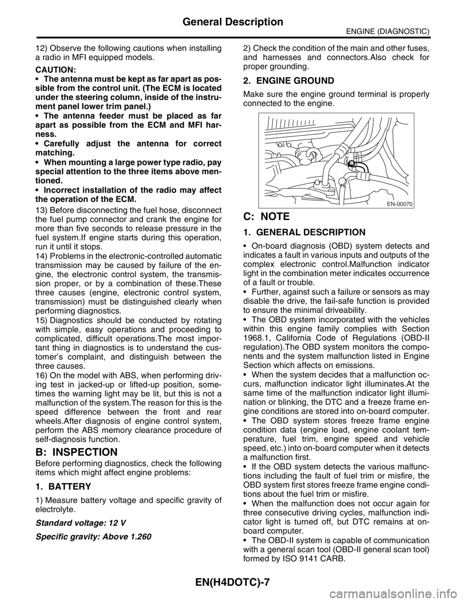
2. ENGINE GROUND
Make sure the engine ground terminal is properly
connected to the engine.
C: NOTE
1. GENERAL DESCRIPTION
On-board diagnosis (OBD) system detects and
indicates a fault in various inputs and outputs of the
complex electronic control.Malfunction indicator
light in the combination meter indicates occurrence
of a fault or trouble.
Further, against such a failure or sensors as may
disable the drive, the fail-safe function is provided
to ensure the minimal driveability.
The OBD system incorporated with the vehicles
within this engine family complies with Section
1968.1, California Code of Regulations (OBD-II
regulation).The OBD system monitors the compo-
nents and the system malfunction listed in Engine
Section which affects on emissions.
When the system decides that a malfunction oc-
curs, malfunction indicator light illuminates.At the
same time of the malfunction indicator light illumi-
nation or blinking, the DTC and a freeze frame en-
gine conditions are stored into on-board computer.
The OBD system stores freeze frame engine
condition data (engine load, engine coolant tem-
perature, fuel trim, engine speed and vehicle
speed, etc.) into on-board computer when it detects
a malfunction first.
If the OBD system detects the various malfunc-
tions including the fault of fuel trim or misfire, the
OBD system first stores freeze frame engine condi-
tions about the fuel trim or misfire.
When the malfunction does not occur again for
three consecutive driving cycles, malfunction indi-
cator light is turned off, but DTC remains at on-
board computer.
The OBD-II system is capable of communication
with a general scan tool (OBD-II general scan tool)
formed by ISO 9141 CARB.
EN-00070
Page 1782 of 2870

EN(H4DOTC)-149
ENGINE (DIAGNOSTIC)
Diagnostic Procedure with Diagnostic Trouble Code (DTC)
AF:DTC P0172 SYSTEM TOO RICH (BANK 1)
DTC DETECTING CONDITION:
Two consecutive driving cycles with fault
TROUBLE SYMPTOM:
Erroneous idling
Engine stalls.
Poor driving performance
CAUTION:
After repair or replacement of faulty parts, conduct Clear Memory Mode
Step Check Yes No
1 CHECK EXHAUST SYSTEM.Are there holes or looseness of
the bolts on exhaust system?Repair exhaust
system.Go to step 2.
2 CHECK AIR INTAKE SYSTEM.Are there holes, loose bolts or
disconnection of hose on air
intake system?Repair air intake
system.Go to step 3.
3 CHECK FUEL PRESSURE.
Warning:
Place “NO FIRE” signs near the working
area.
Be careful not to spill fuel.
1) Release the fuel pressure.
(1) Disconnect the connector from fuel
pump relay.
(2) Start the engine and run it until it stalls.
(3) After the engine stalls, crank it for five
more seconds.
(4) Turn the ignition switch to OFF.
2) Connect the connector to fuel pump relay.
3) Disconnect the fuel delivery hose from fuel
filter, and connect the fuel pressure gauge.
4) Install the fuel filler cap.
5) Start the engine and idle while gear posi-
tion is neutral.
6) Measure the fuel pressure while discon-
necting pressure regulator vacuum hose from
intake manifold.
Warning:
Release fuel pressure before removing the
fuel pressure gauge.
N
OTE:
If fuel pressure does not increase, squeeze the
fuel return hose 2 to 3 times, then measure fuel
pressure again.Is measured value 284 — 314
kPa (2.9 — 3.2 kg/cm
2, 41 —
46 psi)?Go to step 4.Repair the follow-
ing items.
Fuel pressure is
too high:
Clogged fuel
return line or
bent hose
Fuel pressure is
too low:
Improper fuel
pump discharge
Clogged fuel
supply line
Page 1932 of 2870

FU(H4DOTC 2.5)-2
FUEL INJECTION (FUEL SYSTEM)
General Description
1. General Description
A: SPECIFICATION
Fuel tankCapacity 602 (15.9 US gal, 13.2 Imp gal)
Location Under rear seat
Fuel pumpType Impeller
Shutoff discharge pressure
450 — 677 kPa (4.59 — 6.9 kg/cm
2, 65.27 — 98.2 psi)
Discharge flowMore than 1302 (34.3 US gal, 28.6 Imp gal)/h
[12 V at 300 kPa (3.06 kg/cm
2, 43.5 psi)]
Fuel filterCartridge type
Page 1941 of 2870

FU(H4DOTC 2.5)-11
FUEL INJECTION (FUEL SYSTEM)
General Description
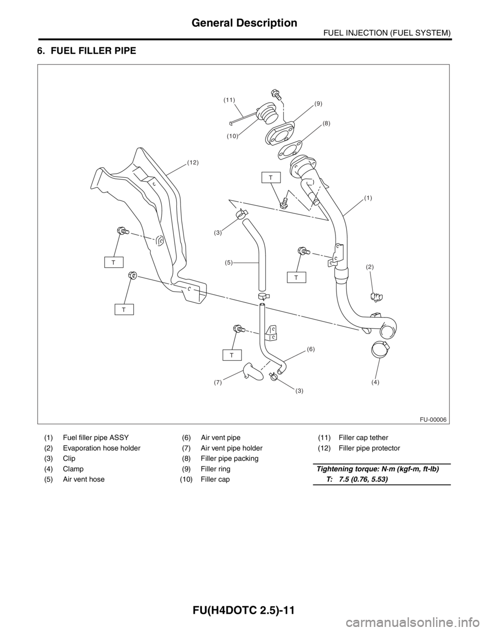
6. FUEL FILLER PIPE
(1) Fuel filler pipe ASSY (6) Air vent pipe (11) Filler cap tether
(2) Evaporation hose holder (7) Air vent pipe holder (12) Filler pipe protector
(3) Clip (8) Filler pipe packing
(4) Clamp (9) Filler ringTightening torque: N·m (kgf-m, ft-lb)
(5) Air vent hose (10) Filler capT: 7.5 (0.76, 5.53)
FU-00006
(4)
(2)
(8)
(1)
(12)(11)
(6)
(7)
(9)
(10)
(5)
(3)
(3)
T
T
T
T
T
Page 1942 of 2870

FU(H4DOTC 2.5)-12
FUEL INJECTION (FUEL SYSTEM)
General Description
C: CAUTION
Wear working clothing, including a cap, protec-
tive goggles, and protective shoes during opera-
tion.
Remove contamination including dirt and corro-
sion before removal, installation or disassembly.
Keep the disassembled parts in order and pro-
tect them from dust or dirt.
Before removal, installation or disassembly, be
sure to clarify the failure. Avoid unnecessary re-
moval, installation, disassembly, and replacement. Be careful not to burn yourself, because each
part on the vehicle is hot after running.
Be sure to tighten fasteners including bolts and
nuts to the specified torque.
Place shop jacks or rigid racks at the specified
points.
Before disconnecting electrical connectors of
sensors or units, be sure to disconnect negative
terminal from battery.
Place “NO FIRE” signs near the working area.
Be careful not to spill fuel on the floor.
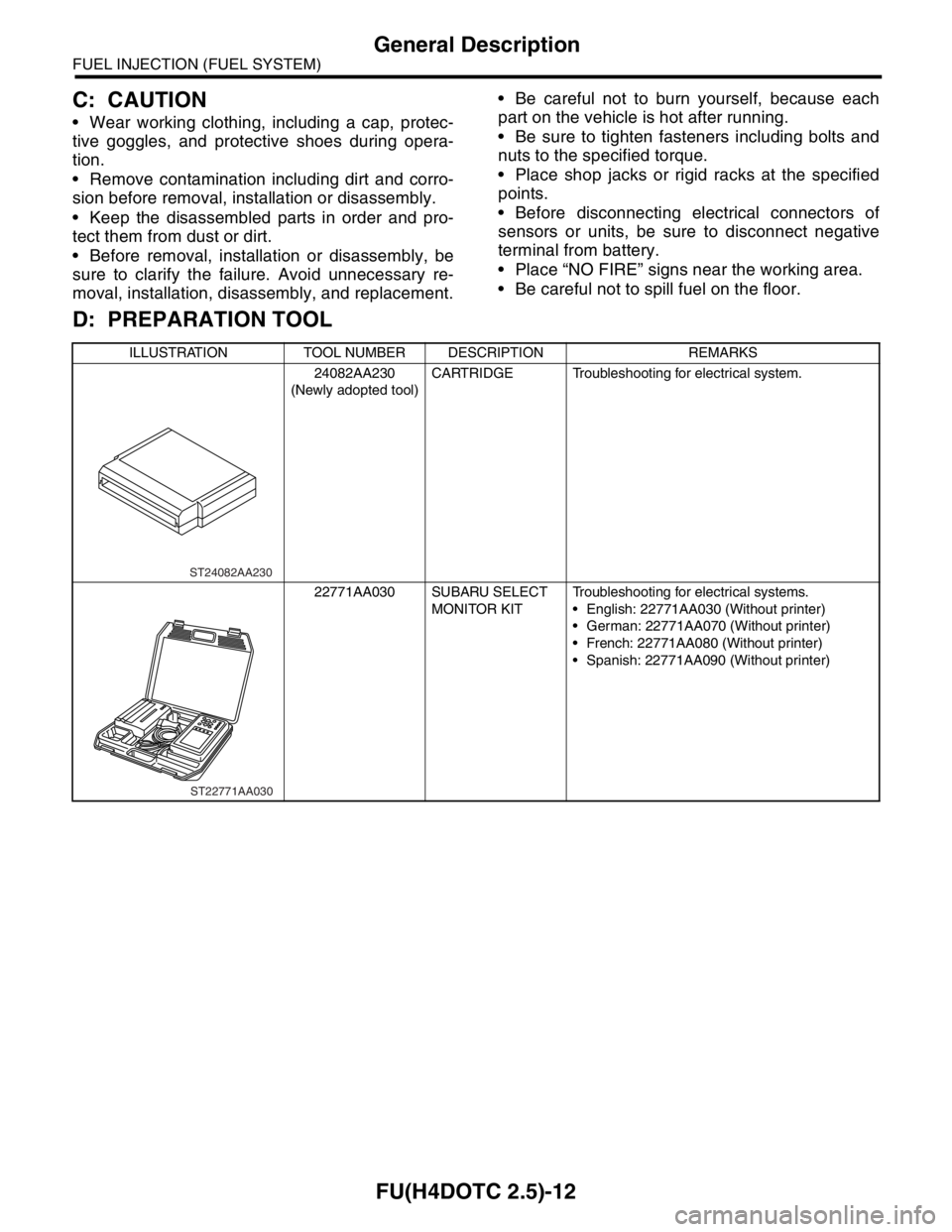
D: PREPARATION TOOL
ILLUSTRATION TOOL NUMBER DESCRIPTION REMARKS
24082AA230
(Newly adopted tool)CARTRIDGE Troubleshooting for electrical system.
22771AA030 SUBARU SELECT
MONITOR KITTroubleshooting for electrical systems.
English: 22771AA030 (Without printer)
German: 22771AA070 (Without printer)
French: 22771AA080 (Without printer)
Spanish: 22771AA090 (Without printer)
ST24082AA230
ST22771AA030