Page 1393 of 2870
FU(H4DOTC)-38
FUEL INJECTION (FUEL SYSTEM)
Fuel Injector
13.Fuel Injector
A: REMOVAL
1. RH SIDE
1) Release the fuel pressure.
54, RELEASING OF FUEL PRESSURE, OPERA-
TION, Fuel.>
2) Open the fuel filler flap lid and remove the fuel
filler cap.
3) Disconnect the ground cable from battery.
4) Remove the intake manifold.
FU(H4DOTC)-14, REMOVAL, Intake Manifold.>
5) Remove the fuel pipe protector RH.
NOTE:
Bolt (A) is tightened together with ground cable.
6) Disconnect the connector from fuel injector.7) Remove the bolts which hold the injector pipe to
intake manifold.
8) Remove the fuel injector while lifting up the fuel
injector pipe.
2. LH SIDE
1) Release the fuel pressure.
54, RELEASING OF FUEL PRESSURE, OPERA-
TION, Fuel.>
2) Open the fuel filler flap lid and remove the fuel
filler cap.
3) Disconnect the ground cable from battery.
FU-00009
FU-00522
(A)
FU-00615
FU-00046
FU-00619
FU-00048
FU-00009
Page 1397 of 2870
FU(H4DOTC)-42
FUEL INJECTION (FUEL SYSTEM)
Tumble Generator Valve Assembly
14.Tumble Generator Valve As-
sembly
A: REMOVAL
1) Release the fuel pressure.
54, RELEASING OF FUEL PRESSURE, OPERA-
TION, Fuel.>
2) Open the fuel filler flap lid, and then remove the
fuel filler cap.
3) Disconnect the ground cable from battery.
4) Remove the intake manifold.
FU(H4DOTC)-14, REMOVAL, Intake Manifold.>
5) Disconnect the connector from tumble generator
valve sensor.
6) Disconnect the connector from tumble generator
valve actuator.
7) Remove the fuel injector.
38, REMOVAL, Fuel Injector.>8) Remove the tumble generator valve body from
intake manifold.
B: INSTALLATION
Install in the reverse order of removal.
NOTE:
Always use new gaskets.
Tightening torque:
8.25 N
⋅m (0.84 kgf-m, 6.1 ft-lb)
FU-00009
FU-00617
FU-00616
FU-00053
FU-00053
Page 1398 of 2870
FU(H4DOTC)-43
FUEL INJECTION (FUEL SYSTEM)
Tumble Generator Valve Actuator
15.Tumble Generator Valve Ac-
tuator
A: REMOVAL
1. RH SIDE
1) Release the fuel pressure.
FU(H4DOTC)-54, RELEASING OF FUEL PRES-
SURE, OPERATION, Fuel.>
2) Open the fuel filler flap lid and remove the fuel
filler cap.
3) Disconnect the ground cable from battery.
4) Remove the intake manifold.
FU(H4DOTC)-14, REMOVAL, Intake Manifold.>
5) Disconnect the connector from tumble generator
valve actuator RH.
6) Remove the tumble generator valve RH.
2. LH SIDE
1) Disconnect the ground cable from battery.
2) Disconnect the connector from tumble generator
valve LH.
3) Remove the tumble generator valve actuator LH.
B: INSTALLATION
1. RH SIDE
Install in the reverse order of removal.
2. LH SIDE
Install in the reverse order of removal.
FU-00009
FU-00621
FU-00009
FU-00622
Page 1409 of 2870
FU(H4DOTC)-54
FUEL INJECTION (FUEL SYSTEM)
Fuel
24.Fuel
A: OPERATION
1. RELEASING OF FUEL PRESSURE
WARNING:
Place “NO FIRE” signs near working area.
Be careful not to spill fuel on floor.
1) Disconnect the connector from fuel pump relay.
2) Start and run the engine until it stalls.
3) After the engine stalls, crank it for 5 more sec-
onds.
4) Turn the ignition switch to OFF.
2. DRAINING FUEL
WARNING:
Place “NO FIRE” signs near working area.
Be careful not to spill fuel on floor.
1) Set the vehicle on a lift.
2) Disconnect the ground cable from battery.
3) Open the fuel filler flap lid and remove the fuel
filler cap.
4) Lift-up the vehicle.5) Drain fuel from the fuel tank.
Set a container under vehicle and remove the drain
plug from fuel tank.
6) Tighten the fuel drain plug.
Tightening torque:
26 N
⋅m (2.7 kgf-m, 19.2 ft-lb)
FU-00262
FU-00009
FU-00089
FU-00089
Page 1413 of 2870
FU(H4DOTC)-58
FUEL INJECTION (FUEL SYSTEM)
Fuel Filler Pipe
26.Fuel Filler Pipe
A: REMOVAL
WARNING:
Place “NO FIRE” signs near working area.
Be careful not to spill fuel on floor.
1) Set the vehicle on a lift.
2) Release the fuel pressure.
FU(H4DOTC)-54, RELEASING OF FUEL PRES-
SURE, OPERATION, Fuel.>
3) Open the fuel filler flap lid and remove the fuel
filler cap.
4) Disconnect the ground cable from battery.
5) Remove the screws holding the packing in place.
6) Loosen the rear right side wheel nuts.
7) Lift-up the vehicle.
8) Remove the rear right side wheel.9) Drain fuel from fuel tank. Set a container under
vehicle and remove the drain plug from fuel tank.
10) Tighten the fuel drain plug, and install the front
right side tank cover.
Tightening torque:
26 N
⋅m (2.7 kgf-m, 19.2 ft-lb)
11) Remove the fuel filler pipe protector.
12) Separate the evaporation hoses from clip of
fuel filler pipe.
FU-00009
FU-00095
FU-00096
FU-00089
FU-00089
FU-00097
FU-00098
Page 1417 of 2870

FU(H4DOTC)-62
FUEL INJECTION (FUEL SYSTEM)
Fuel Pump
27.Fuel Pump
A: REMOVAL
WARNING:
Place “NO FIRE” signs near working area.
Be careful not to spill fuel on floor.
NOTE:
Fuel pump assembly consists of fuel pump and fuel
level sensor.
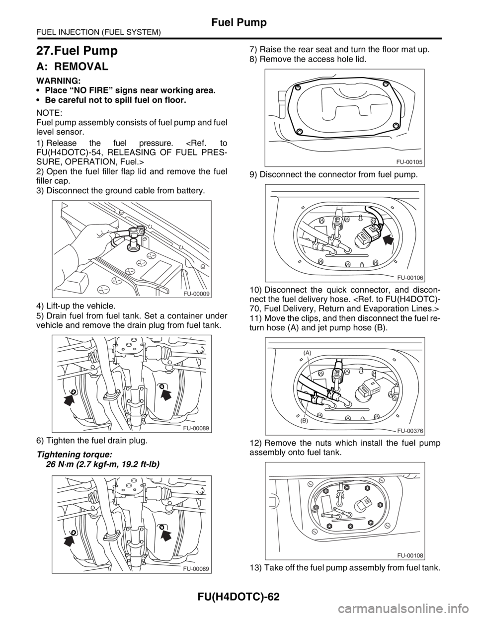
1) Release the fuel pressure.
FU(H4DOTC)-54, RELEASING OF FUEL PRES-
SURE, OPERATION, Fuel.>
2) Open the fuel filler flap lid and remove the fuel
filler cap.
3) Disconnect the ground cable from battery.
4) Lift-up the vehicle.
5) Drain fuel from fuel tank. Set a container under
vehicle and remove the drain plug from fuel tank.
6) Tighten the fuel drain plug.
Tightening torque:
26 N
⋅m (2.7 kgf-m, 19.2 ft-lb)7) Raise the rear seat and turn the floor mat up.
8) Remove the access hole lid.
9) Disconnect the connector from fuel pump.
10) Disconnect the quick connector, and discon-
nect the fuel delivery hose.
70, Fuel Delivery, Return and Evaporation Lines.>
11) Move the clips, and then disconnect the fuel re-
turn hose (A) and jet pump hose (B).
12) Remove the nuts which install the fuel pump
assembly onto fuel tank.
13) Take off the fuel pump assembly from fuel tank.
FU-00009
FU-00089
FU-00089
FU-00105
FU-00106
FU-00376
(B)
(A)
FU-00108
Page 1425 of 2870
FU(H4DOTC)-70
FUEL INJECTION (FUEL SYSTEM)
Fuel Delivery, Return and Evaporation Lines
33.Fuel Delivery, Return and Evaporation Lines
A: REMOVAL
1) Set the vehicle on a lift.
2) Release the fuel pressure.
Fuel.>
3) Open the fuel filler flap lid and remove the fuel filler cap.
4) Remove the floor mat.
5) Remove the fuel delivery pipes and hoses, fuel return pipes and hoses, evaporation pipes and hoses.
6) In the engine compartment, detach the fuel de-
livery hoses (A), return hoses (B) and evaporation
hoses (C).
7) Lift-up the vehicle.8) Disconnect the two-way valve hose (A) from
two-way valve and disconnect the canister hose (B)
from canister.
FU-00122
(B) (A)
(C)
FU-00374
(A)(B)
FU-00091
Page 1492 of 2870

ME(H4DOTC)-36
MECHANICAL
Fuel Pressure
7. Fuel Pressure
A: INSPECTION
CAUTION:
Before removing the fuel pressure gauge, re-
lease the fuel pressure.
NOTE:
If out of specification, check or replace the pressure
regulator and pressure regulator vacuum hose.
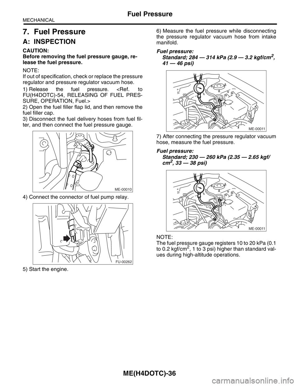
1) Release the fuel pressure.
FU(H4DOTC)-54, RELEASING OF FUEL PRES-
SURE, OPERATION, Fuel.>
2) Open the fuel filler flap lid, and then remove the
fuel filler cap.
3) Disconnect the fuel delivery hoses from fuel fil-
ter, and then connect the fuel pressure gauge.
4) Connect the connector of fuel pump relay.
5) Start the engine.6) Measure the fuel pressure while disconnecting
the pressure regulator vacuum hose from intake
manifold.
Fuel pressure:
Standard; 284 — 314 kPa (2.9 — 3.2 kgf/cm2,
41 — 46 psi)
7) After connecting the pressure regulator vacuum
hose, measure the fuel pressure.
Fuel pressure:
Standard; 230 — 260 kPa (2.35 — 2.65 kgf/
cm
2, 33 — 38 psi)
NOTE:
The fuel pressure gauge registers 10 to 20 kPa (0.1
to 0.2 kgf/cm
2, 1 to 3 psi) higher than standard val-
ues during high-altitude operations.
ME-00010
FU-00262
ME-00011
ME-00011