2004 SUBARU FORESTER stop start
[x] Cancel search: stop startPage 30 of 2870
AC-28
HVAC SYSTEM (HEATER, VENTILATOR AND A/C)
Refrigerant Charging Procedure
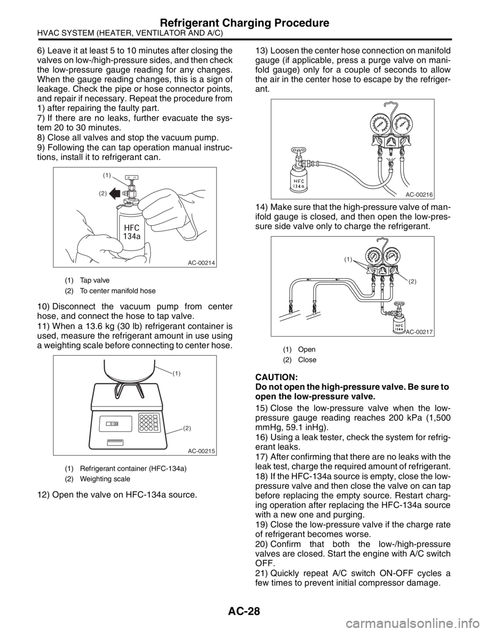
6) Leave it at least 5 to 10 minutes after closing the
valves on low-/high-pressure sides, and then check
the low-pressure gauge reading for any changes.
When the gauge reading changes, this is a sign of
leakage. Check the pipe or hose connector points,
and repair if necessary. Repeat the procedure from
1) after repairing the faulty part.
7) If there are no leaks, further evacuate the sys-
tem 20 to 30 minutes.
8) Close all valves and stop the vacuum pump.
9) Following the can tap operation manual instruc-
tions, install it to refrigerant can.
10) Disconnect the vacuum pump from center
hose, and connect the hose to tap valve.
11) When a 13.6 kg (30 lb) refrigerant container is
used, measure the refrigerant amount in use using
a weighting scale before connecting to center hose.
12) Open the valve on HFC-134a source.13) Loosen the center hose connection on manifold
gauge (if applicable, press a purge valve on mani-
fold gauge) only for a couple of seconds to allow
the air in the center hose to escape by the refriger-
ant.
14) Make sure that the high-pressure valve of man-
ifold gauge is closed, and then open the low-pres-
sure side valve only to charge the refrigerant.
CAUTION:
Do not open the high-pressure valve. Be sure to
open the low-pressure valve.
15) Close the low-pressure valve when the low-
pressure gauge reading reaches 200 kPa (1,500
mmHg, 59.1 inHg).
16) Using a leak tester, check the system for refrig-
erant leaks.
17) After confirming that there are no leaks with the
leak test, charge the required amount of refrigerant.
18) If the HFC-134a source is empty, close the low-
pressure valve and then close the valve on can tap
before replacing the empty source. Restart charg-
ing operation after replacing the HFC-134a source
with a new one and purging.
19) Close the low-pressure valve if the charge rate
of refrigerant becomes worse.
20) Confirm that both the low-/high-pressure
valves are closed. Start the engine with A/C switch
OFF.
21) Quickly repeat A/C switch ON-OFF cycles a
few times to prevent initial compressor damage.
(1) Tap valve
(2) To center manifold hose
(1) Refrigerant container (HFC-134a)
(2) Weighting scale
AC-00214
(1)
(2)
AC-00215
(1)
(2)
(1) Open
(2) Close
AC-00216
AC-00217
(1)
(2)
Page 32 of 2870
AC-30
HVAC SYSTEM (HEATER, VENTILATOR AND A/C)
Refrigerant Leak Check
5. Refrigerant Leak Check
A: INSPECTION
1) Operate the A/C system for approx. 10 minutes,
and confirm that the high-pressure side shows at
least 690 kPa (7.03 kg/cm
2, 100 psi). Then stop the
engine to start the leak test.
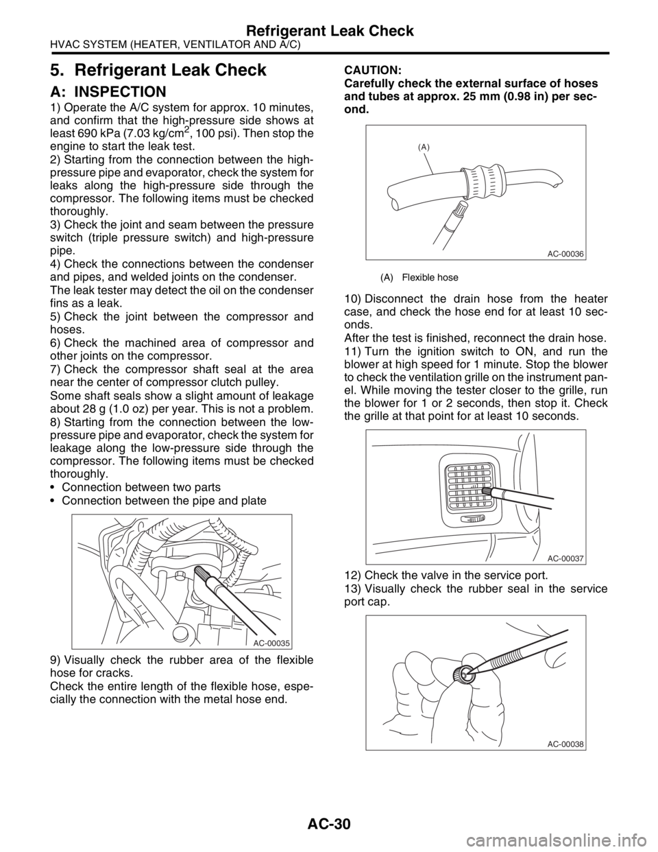
2) Starting from the connection between the high-
pressure pipe and evaporator, check the system for
leaks along the high-pressure side through the
compressor. The following items must be checked
thoroughly.
3) Check the joint and seam between the pressure
switch (triple pressure switch) and high-pressure
pipe.
4) Check the connections between the condenser
and pipes, and welded joints on the condenser.
The leak tester may detect the oil on the condenser
fins as a leak.
5) Check the joint between the compressor and
hoses.
6) Check the machined area of compressor and
other joints on the compressor.
7) Check the compressor shaft seal at the area
near the center of compressor clutch pulley.
Some shaft seals show a slight amount of leakage
about 28 g (1.0 oz) per year. This is not a problem.
8) Starting from the connection between the low-
pressure pipe and evaporator, check the system for
leakage along the low-pressure side through the
compressor. The following items must be checked
thoroughly.
Connection between two parts
Connection between the pipe and plate
9) Visually check the rubber area of the flexible
hose for cracks.
Check the entire length of the flexible hose, espe-
cially the connection with the metal hose end.CAUTION:
Carefully check the external surface of hoses
and tubes at approx. 25 mm (0.98 in) per sec-
ond.
10) Disconnect the drain hose from the heater
case, and check the hose end for at least 10 sec-
onds.
After the test is finished, reconnect the drain hose.
11) Turn the ignition switch to ON, and run the
blower at high speed for 1 minute. Stop the blower
to check the ventilation grille on the instrument pan-
el. While moving the tester closer to the grille, run
the blower for 1 or 2 seconds, then stop it. Check
the grille at that point for at least 10 seconds.
12) Check the valve in the service port.
13) Visually check the rubber seal in the service
port cap.
AC-00035
(A) Flexible hose
AC-00036
(A)
AC-00037
AC-00038
Page 75 of 2870

AC-19
HVAC SYSTEM (AUTO A/C)(DIAGNOSTIC)
Diagnostics for A/C System Malfunction
9 CHECK OPERATION OF MAIN FAN MOTOR.
1) Start the engine and turn the A/C switch to
ON.
2) Check the operation of main fan motor.Does the main fan motor oper-
ate normally?Go to step 14.Go to step 10.
10 CHECK POWER SUPPLY TO MAIN FAN MO-
TOR.
CAUTION:
Be careful not to overheat the engine during
repair.
1) Turn the ignition switch to OFF.
2) Disconnect the connector from main fan
motor.
3) Start the engine, and warm it up until
engine coolant temperature increases over
100°C (212°F).
4) Stop the engine and turn ignition switch to
ON.
5) Measure the voltage between main fan
motor harness connector and chassis ground.
Connector & terminal
Except turbo AT model:
(F17) No. 2 (+) — Chassis ground (
−):
Turbo AT model:
(F17) No. 1 (+) — Chassis ground (
−):Is the voltage more than 10 V? Go to step 11.Repair the har-
ness for main fan
motor power sup-
ply circuit.
11 CHECK GROUND CIRCUIT OF MAIN FAN
MOTOR.
Measure the resistance between main fan
motor harness connector and chassis ground.
Connector & terminal
Except turbo AT model:
(F17) No. 1 — Chassis ground:
Turbo AT model:
(F17) No. 2 — Chassis ground:Is the resistance less than 1
Ω?Go to step 12.Repair the har-
ness for main fan
motor ground cir-
cuit.
12 CHECK MAIN FAN MOTOR.
Connect the battery positive (+) terminal to ter-
minal No. 2, and ground (−) terminal to termi-
nal No. 1 of main fan motor connector to make
sure that main fan motor rotate.Does the main fan rotate? Go to step 13.Replace the main
fan motor.
13 CHECK POOR CONTACT IN MAIN FAN MO-
TOR CONNECTOR.
Check poor contact in main fan motor harness
connector.Is there poor contact in con-
nector?Go to step 14.Repair the poor
contact in main fan
motor connector.
14 CHECK OPERATION OF SUB FAN MOTOR.
1) Start the engine and turn the A/C switch to
ON.
2) Check the operation of sub fan motor.Does the sub fan motor oper-
ate normally?Go to step 19.Go to step 15. Step Check Yes No
Page 76 of 2870

AC-20
HVAC SYSTEM (AUTO A/C)(DIAGNOSTIC)
Diagnostics for A/C System Malfunction
15 CHECK POWER SUPPLY TO SUB FAN MO-
TOR.
CAUTION:
Be careful not to overheat the engine during
repair.
1) Turn the ignition switch to OFF.
2) Disconnect the connector from sub fan
motor.
3) Start the engine, and warm it up until
engine coolant temperature increases over
100°C (212°F).
4) Stop the engine and turn ignition switch to
ON.
5) Measure the voltage between sub fan
motor harness connector and chassis ground.
Connector & terminal
Except turbo AT model:
(F16) No. 2 (+) — Chassis ground (
−):
Turbo AT model:
(F16) No. 1 (+) — Chassis ground (
−):Is the voltage more than 10 V? Go to step 16.Repair the har-
ness for sub fan
motor power sup-
ply circuit.
16 CHECK GROUND CIRCUIT OF SUB FAN
MOTOR.
Measure the resistance between sub fan motor
harness connector and chassis ground.
Connector & terminal
Except turbo AT model:
(F16) No. 1 — Chassis ground:
Turbo AT model:
(F16) No. 2 — Chassis ground:Is the resistance less than 1
Ω?Go to step 17.Repair the har-
ness for sub fan
motor ground cir-
cuit.
17 CHECK SUB FAN MOTOR.
Connect the battery positive (+) terminal to ter-
minal No. 2, and ground (−) terminal to termi-
nal No. 1 of sub fan motor connector to make
sure that sub fan motor rotate.Does the sub fan motor rotate? Go to step 18.Replace the sub
fan motor.
18 CHECK POOR CONTACT IN SUB FAN MO-
TOR CONNECTOR.
Check poor contact in sub fan motor connec-
tor.Is there poor contact in con-
nector?Go to step 19.Repair the poor
contact in sub fan
motor connector.
19 CHECK POOR CONTACT IN AUTO A/C
CONTROL MODULE CONNECTOR.
Check poor contact in auto A/C control module
connector.Is there poor contact in con-
nector?Replace the auto
A/C control mod-
ule.Repair the con-
nector. Step Check Yes No
Page 120 of 2870
AB-20
AIRBAG SYSTEM
Roll Connector
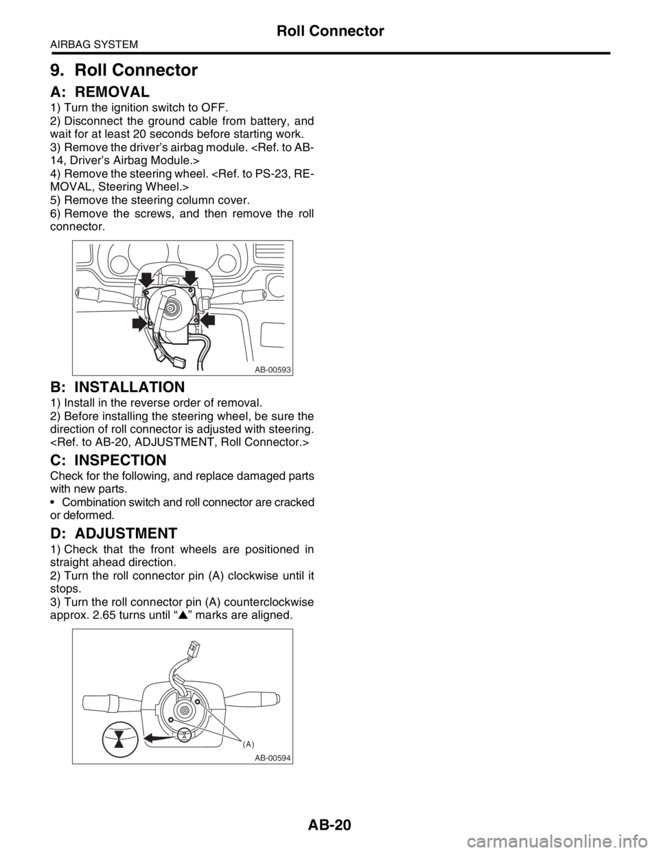
9. Roll Connector
A: REMOVAL
1) Turn the ignition switch to OFF.
2) Disconnect the ground cable from battery, and
wait for at least 20 seconds before starting work.
3) Remove the driver’s airbag module.
4) Remove the steering wheel.
5) Remove the steering column cover.
6) Remove the screws, and then remove the roll
connector.
B: INSTALLATION
1) Install in the reverse order of removal.
2) Before installing the steering wheel, be sure the
direction of roll connector is adjusted with steering.
C: INSPECTION
Check for the following, and replace damaged parts
with new parts.
Combination switch and roll connector are cracked
or deformed.
D: ADJUSTMENT
1) Check that the front wheels are positioned in
straight ahead direction.
2) Turn the roll connector pin (A) clockwise until it
stops.
3) Turn the roll connector pin (A) counterclockwise
approx. 2.65 turns until “▲” marks are aligned.
AB-00593
AB-00594
(A)
Page 713 of 2870
![SUBARU FORESTER 2004 Service Repair Manual ID-4
IDENTIFICATION
Identification
2. MEANING OF V.I.N.
The meaning of the VIN is as follows:
Europe, Australia and General (Except GCC)
]JF1SG5LK44G002001[
The starting and ending brackets ( ][ ) a SUBARU FORESTER 2004 Service Repair Manual ID-4
IDENTIFICATION
Identification
2. MEANING OF V.I.N.
The meaning of the VIN is as follows:
Europe, Australia and General (Except GCC)
]JF1SG5LK44G002001[
The starting and ending brackets ( ][ ) a](/manual-img/17/57426/w960_57426-712.png)
ID-4
IDENTIFICATION
Identification
2. MEANING OF V.I.N.
The meaning of the VIN is as follows:
Europe, Australia and General (Except GCC)
]JF1SG5LK44G002001[
The starting and ending brackets ( ][ ) are stop marks.
GCC countries (Saudi Arabia, etc.)
]JF1SG93MX4J002001[
The starting and ending brackets ( ][ ) are stop marks.
Digits Code Meaning Details
1 to 3 JF1 Manufacturer body area JF1: Passengercar, FHI made
JF2: MPV, FHI made
4 S Car line S: FORESTER
5 G Body type G: Wagon
6 5 Displacement 5: 2.0L AWD
9: 2.5L AWD
7 L Steering position K: RHD (Right-hand drive)
L: LHD (Left-hand drive)
8 K Engine & transmission R: SOHC MPI 4-speed AT
K: SOHC MPI Full-time AWD 5-speed MT Dual range
D: DOHC Turbo Full-time AWD 5-speed MT
T: DOHC Turbo 4-speed D-AT
9 4 Drive type 3: Full-time AWD Single range
4: Full-time AWD Dual range
5: AWD AT
10 4 Model year 3: 2003MY
4: 2004MY
5: 2005MY
11 G Factory location G: FHI (Gunma)
12 to 17 002001 Serial number —
Digits Code Meaning Details
1 to 3 JF1 Manufacturer body area JF1: Passenger car, FHI made
4 S Car line S: FORESTER
5 G Body type G: Wagon
6 9 Displacement 9: 2.5L AWD
7 3 Grade 3: 2.5X
8 M Restraint M: Manual belts, dual airbag
9 X Check digit 0 — 9 & X
10 4 Model year 3: 2003MY
4: 2004MY
5: 2005MY
11 J Transmission type H: Full-time AWD 4-speed AT
J: Full-time AWD 5-speed MT dual range
12 to 17 002001 Serial number —
Page 733 of 2870
PI-10
PRE-DELIVERY INSPECTION
Pre-delivery Inspection
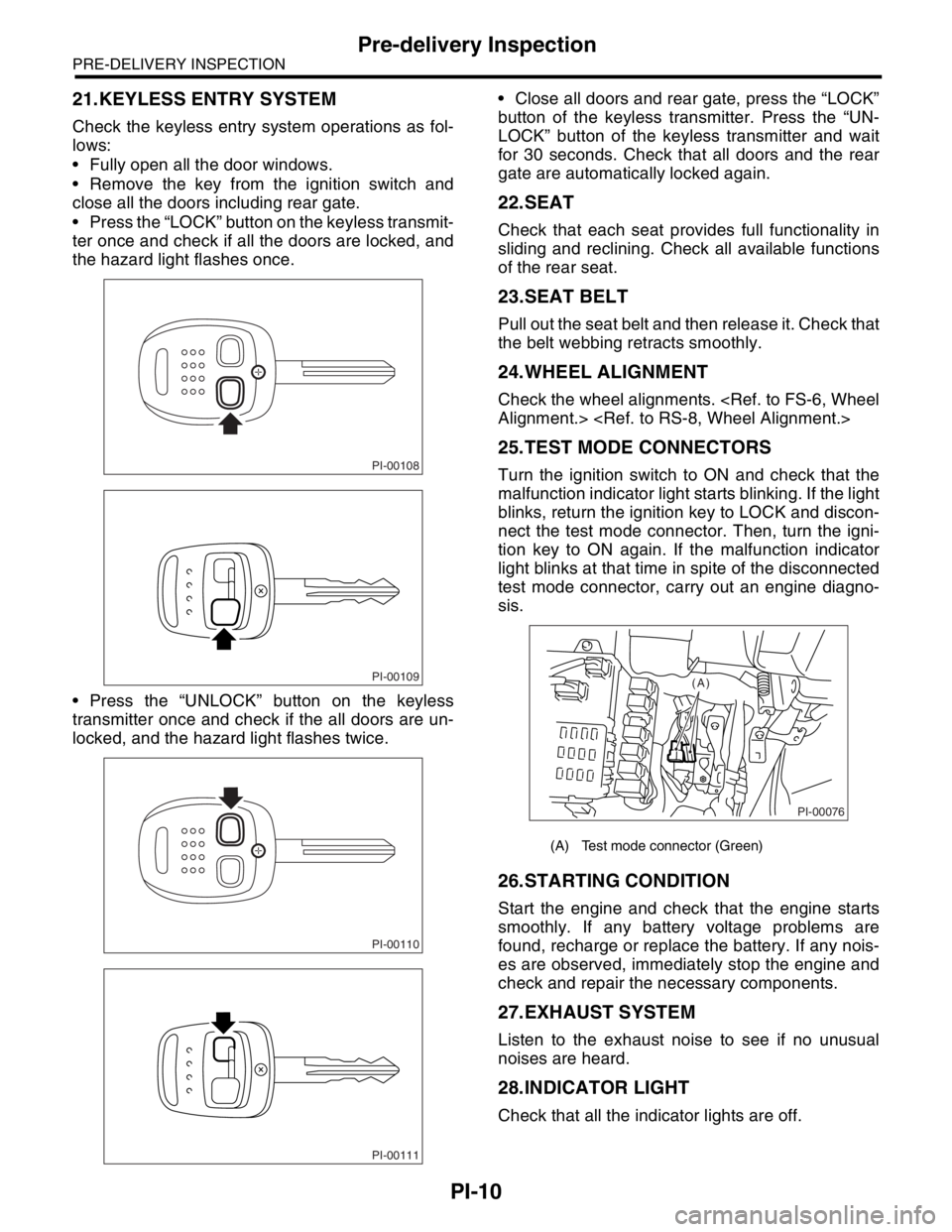
21.KEYLESS ENTRY SYSTEM
Check the keyless entry system operations as fol-
lows:
Fully open all the door windows.
Remove the key from the ignition switch and
close all the doors including rear gate.
Press the “LOCK” button on the keyless transmit-
ter once and check if all the doors are locked, and
the hazard light flashes once.
Press the “UNLOCK” button on the keyless
transmitter once and check if the all doors are un-
locked, and the hazard light flashes twice. Close all doors and rear gate, press the “LOCK”
button of the keyless transmitter. Press the “UN-
LOCK” button of the keyless transmitter and wait
for 30 seconds. Check that all doors and the rear
gate are automatically locked again.
22.SEAT
Check that each seat provides full functionality in
sliding and reclining. Check all available functions
of the rear seat.
23.SEAT BELT
Pull out the seat belt and then release it. Check that
the belt webbing retracts smoothly.
24.WHEEL ALIGNMENT
Check the wheel alignments.
25.TEST MODE CONNECTORS
Turn the ignition switch to ON and check that the
malfunction indicator light starts blinking. If the light
blinks, return the ignition key to LOCK and discon-
nect the test mode connector. Then, turn the igni-
tion key to ON again. If the malfunction indicator
light blinks at that time in spite of the disconnected
test mode connector, carry out an engine diagno-
sis.
26.STARTING CONDITION
Start the engine and check that the engine starts
smoothly. If any battery voltage problems are
found, recharge or replace the battery. If any nois-
es are observed, immediately stop the engine and
check and repair the necessary components.
27.EXHAUST SYSTEM
Listen to the exhaust noise to see if no unusual
noises are heard.
28.INDICATOR LIGHT
Check that all the indicator lights are off.
PI-00108
PI-00109
PI-00110
PI-00111
(A) Test mode connector (Green)
PI-00076
(A)
Page 745 of 2870
PM-8
PERIODIC MAINTENANCE SERVICE
Engine Oil
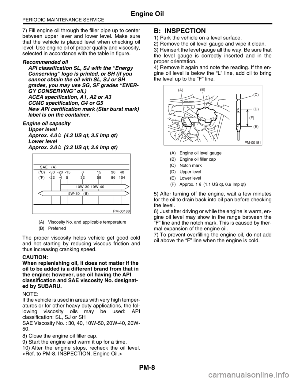
7) Fill engine oil through the filler pipe up to center
between upper lever and lower level. Make sure
that the vehicle is placed level when checking oil
level. Use engine oil of proper quality and viscosity,
selected in accordance with the table in figure.
Recommended oil
API classification SL, SJ with the “Energy
Conserving” logo is printed, or SH (if you
cannot obtain the oil with SL, SJ or SH
grades, you may use SG, SF grades “ENER-
GY CONSERVING” oil.)
ACEA specification, A1, A2 or A3
CCMC specification, G4 or G5
New API certification mark (Star burst mark)
label is on the container.
Engine oil capacity
Upper level
Approx. 4.02 (4.2 US qt, 3.5 Imp qt)
Lower level
Approx. 3.02 (3.2 US qt, 2.6 Imp qt)
The proper viscosity helps vehicle get good cold
and hot starting by reducing viscous friction and
thus increasing cranking speed.
CAUTION:
When replenishing oil, it does not matter if the
oil to be added is a different brand from that in
the engine; however, use oil having the API
classification and SAE viscosity No. designat-
ed by SUBARU.
NOTE:
If the vehicle is used in areas with very high temper-
atures or for other heavy duty applications, the fol-
lowing viscosity oils may be used: API
classification: SL, SJ or SH
SAE Viscosity No. : 30, 40, 10W-50, 20W-40, 20W-
50.
8) Close the engine oil filler cap.
9) Start the engine and warm it up for a time.
10) After the engine stops, recheck the oil level.
1) Park the vehicle on a level surface.
2) Remove the oil level gauge and wipe it clean.
3) Reinsert the level gauge all the way. Be sure that
the level gauge is correctly inserted and in the
proper orientation.
4) Remove it again and note the reading. If the en-
gine oil level is below the “L” line, add oil to bring
the level up to the “F” line.
5) After turning off the engine, wait a few minutes
for the oil to drain back into oil pan before checking
the level.
6) Just after driving or while the engine is warm, en-
gine oil level may show in the range between the
“F” line and the notch mark. This is caused by ther-
mal expansion of the engine oil.
7) To prevent overfilling the engine oil, do not add
oil above the “F” line when the engine is cold.
(A) Viscosity No. and applicable temperature
(B) Preferred
PM-00188
40 30 15 0 -15 -20 -30 ( C)
104 86 59 32
10W-30,10W-40 5 -4 -22 ( F)
SAE (A)
5W-30 (B)
(A) Engine oil level gauge
(B) Engine oil filler cap
(C) Notch mark
(D) Upper level
(E) Lower level
(F) Approx. 12 (1.1 US qt, 0.9 Imp qt)
PM-00181
(A)(B)
(D)
(E) (F)(C)