Page 60 of 2870

AC-4
HVAC SYSTEM (AUTO A/C)(DIAGNOSTIC)
General Description
5. CONTROL SWITCHES
Start and warm-up the engine completely.
1) Inspection using switches
2) Compressor operation inspection
3) Inspection of illumination control
No. Point to check Switch operation Judgment standard
1 Fan speed control dial Turn the fan speed control dial clockwise.Fan speed changes 1st → 2nd → 3rd → 4th
as dial turn.
2AUTO switch1) Press the AUTO switch.
2) Turn the temperature control dial to the left
fully, and set maximum cool position. Outlet air temperature: COOL
Fan speed: 4th
Outlet opening: VENT
Inlet opening: RECIRC
Compressor: AUTO
3) Turn the temperature control dial to the right
slowly, and change the setting from maximum
cool position to maximum hot position gradually. Outlet air temperature: COOL → HOT
Fan speed: AUTO
Outlet opening: AUTO
Inlet opening: AUTO
Compressor: AUTO
4) Turn the temperature control dial to the right
fully, and set maximum hot position. Outlet air temperature: HOT
Fan speed: 4th
Outlet opening: HEAT
Inlet opening: FRESH
Compressor: AUTO
3 Defroster switch Press the defroster switch. Outlet air temperature: AUTO
Fan speed: AUTO
Outlet opening: DEF
Inlet opening: FRESH
Compressor: ON
4FRESH/RECIRC
switchPress the FRESH/RECIRC switch.Inlet opening switches RECIRC → FRESH or
FRESH → RECIRC each time pressing the
switch.
5 Mode control dial Press the mode control dial.Outlet opening switches VENT → BI-LEVEL
→ HEAT → DEF/HEAT each time dialing
clockwise.
No. Point to check Switch operation Judgment standard
1 Compressor1) A/C switch is turned to ON.
2) Turn the fan speed control clockwise.Compressor: ON
No. Point to check Switch operation Judgment standard
1 Illumination1) Turn the lighting switch to ON. Illumination comes on.
2) Press the OFF switch one second or more. Illumination dimming is cancelled.
Page 71 of 2870

AC-15
HVAC SYSTEM (AUTO A/C)(DIAGNOSTIC)
Diagnostics for A/C System Malfunction
Step Check Yes No
1 CHECK FUSE.
1) Remove the fuse No. 1, 2 and 17 from fuse
& relay box.
2) Check the condition of fuse.Is any fuse blown-out? Replace the fuse. Go to step 2.
2 CHECK POWER SUPPLY FOR BLOWER
MOTOR.
1) Turn the ignition switch to ON.
2) Turn the fan speed control dial clockwise.
3) Measure the voltage between blower motor
and chassis ground.
Connector & terminal
(B87) No. 1 (+) — Chassis ground (
−):Is the voltage more than 8 V (at
normal temperature)?Go to step 3.Repair the open
circuit of blower
motor power sup-
ply line harness.
3 CHECK BLOWER MOTOR RELAY.
1) Turn the ignition switch to OFF.
2) Remove the blower motor relay.
3) Connect the battery positive (+) terminal to
terminal No. 1 of blower motor relay, and nega-
tive (−) terminal to terminal No. 3.
4) Measure the resistance between terminals
No. 2 and 4.
Te r m i n a l s
No. 2 — No. 4:Is the resistance less than 1
Ω?Go to step 4.Replace the
blower motor relay.
4 CHECK BLOWER MOTOR.
1) Disconnect the connector from blower
motor.
2) Connect the battery positive (+) terminal to
terminal No. 1 of blower motor connector, and
negative (−) terminal to terminal No. 2 and No.
5.
3) Make sure the blower motor runs.Does the blower motor run? Go to step 5.Replace the
blower motor.
5 CHECK POOR CONTACT.
Check poor contact in auto A/C control module
connector.Is there poor contact in con-
nector?Repair the con-
nector.Replace the auto
A/C control mod-
ule.
Page 120 of 2870

AB-20
AIRBAG SYSTEM
Roll Connector
9. Roll Connector
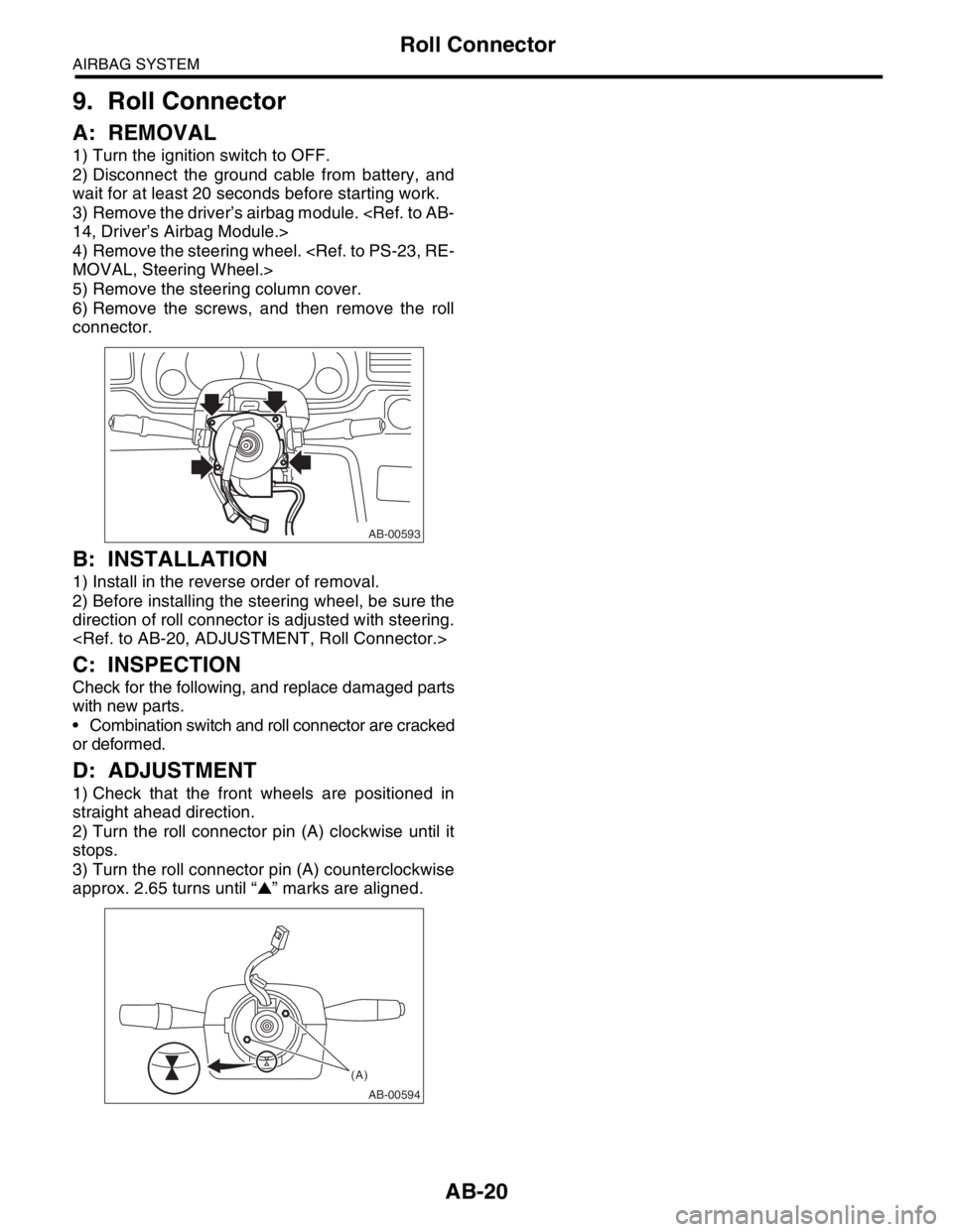
A: REMOVAL
1) Turn the ignition switch to OFF.
2) Disconnect the ground cable from battery, and
wait for at least 20 seconds before starting work.
3) Remove the driver’s airbag module.
14, Driver’s Airbag Module.>
4) Remove the steering wheel.
MOVAL, Steering Wheel.>
5) Remove the steering column cover.
6) Remove the screws, and then remove the roll
connector.
B: INSTALLATION
1) Install in the reverse order of removal.
2) Before installing the steering wheel, be sure the
direction of roll connector is adjusted with steering.
C: INSPECTION
Check for the following, and replace damaged parts
with new parts.
Combination switch and roll connector are cracked
or deformed.
D: ADJUSTMENT
1) Check that the front wheels are positioned in
straight ahead direction.
2) Turn the roll connector pin (A) clockwise until it
stops.
3) Turn the roll connector pin (A) counterclockwise
approx. 2.65 turns until “▲” marks are aligned.
AB-00593
AB-00594
(A)
Page 358 of 2870
GW-28
GLASS/WINDOW/MIRROR
Inner Rearview Mirror
14.Inner Rearview Mirror
A: REMOVAL
NOTE:
The spring cannot be reused. Prepare a new spring
before removal.
1) Turn the mirror base 90 degrees clockwise or
counterclockwise to remove it.
2) Remove the spring from mirror base.
CAUTION:
Be careful not to damage the mirror surface.
3) If the mirror base is damaged, remove the mirror
base using piano wire or spatula, etc.
CAUTION:
Be careful not to damage the windshield glass.
B: INSTALLATION
1) If removing the mirror base, remove the remain-
ing adhesive thoroughly, and then fit the mirror
base to mark on windshield glass to install.
Adhesive:
REPAIR KIT IN MR (Part No. 65029FC000)
2) Verify that the mirror base is adhered securely,
and then install the spring.
3) Install in the reverse order of removal.
C: INSPECTION
1) Check that the mirror is not damaged.
2) Check that the spring is not damaged.
GW-00046
GW-00047
Page 527 of 2870
EI-51
EXTERIOR/INTERIOR TRIM
Instrument Panel Center Compartment
25.Instrument Panel Center
Compartment
A: REMOVAL
1) Disconnect the ground cable from battery.
2) Insert a flat tip screwdriver, and then pry up to re-
move the clips.
3) Remove the instrument panel center compartment
from instrument panel.
4) Disconnect the connector from clock.
B: INSTALLATION
Install in the reverse order of removal.
(A) Clip
EI-00081: A
Page 727 of 2870

PI-4
PRE-DELIVERY INSPECTION
Pre-delivery Inspection
Checks with the Engine Running
Dynamic Test with the Vehicle Running
Checks after Dynamic Test
Step Check point
26. Test mode connectors Test mode connectors
27. Starting condition Start the engine and check that the engine starts smoothly.
28. Exhaust system Check that the exhaust noise is normal and no leaks are found.
29. Indicator light Check that all the indicator lights operate normally.
30. Clock Check that the clock operates normally.
31. Radio Check that the radio system operates normally.
32. Front accessory power supply socket Check that the front accessory power supply socket operates normally.
33. Lighting system Check that the lighting systems operate normally.
34. Window washer Check that the window washer system operates normally.
35. Wiper Check that the wiper system operates normally.
36. Power window operation check Check the power window for correct operations.
Step Check point
37. Brake test Check that the foot brake operates normally.
38. Parking brake Check that the parking brake operates normally.
39. AT shift control Check the AT shift patterns are correct.
40. Heater & ventilation Check that the heater & ventilation system operates normally.
41. Air conditioner Check that the air conditioner operates normally.
42. Speed control Check that the speed control operates normally.
Step Check point
43. ATF level Check that the ATF level is normal.
44. Power steering fluid level Check that the power steering fluid level is normal.
45. Fluid leak check Check for fluid/oil leaks.
46. Water leak check Spray the vehicle with water and check for water leaks.
47. Appearance check 2 (1) Remove the protective coating (wrap guard).(if any)
(2) Check the body paints for damage and smears.
(3) Check the plated parts for damage and rust.
Page 734 of 2870

PI-11
PRE-DELIVERY INSPECTION
Pre-delivery Inspection
29.CLOCK
Check the clock for normal operations and enough
accuracy.
30.RADIO
Check the radio for full functionality and normal
noise level. Also check the CD unit operations.
31.FRONT ACCESSORY POWER SUPPLY
SOCKET
Check the front accessory power supply socket op-
erations.
32.LIGHTING SYSTEM
Check the headlight operations.
Check the brake light operations.
Check the other lights for normal operations.
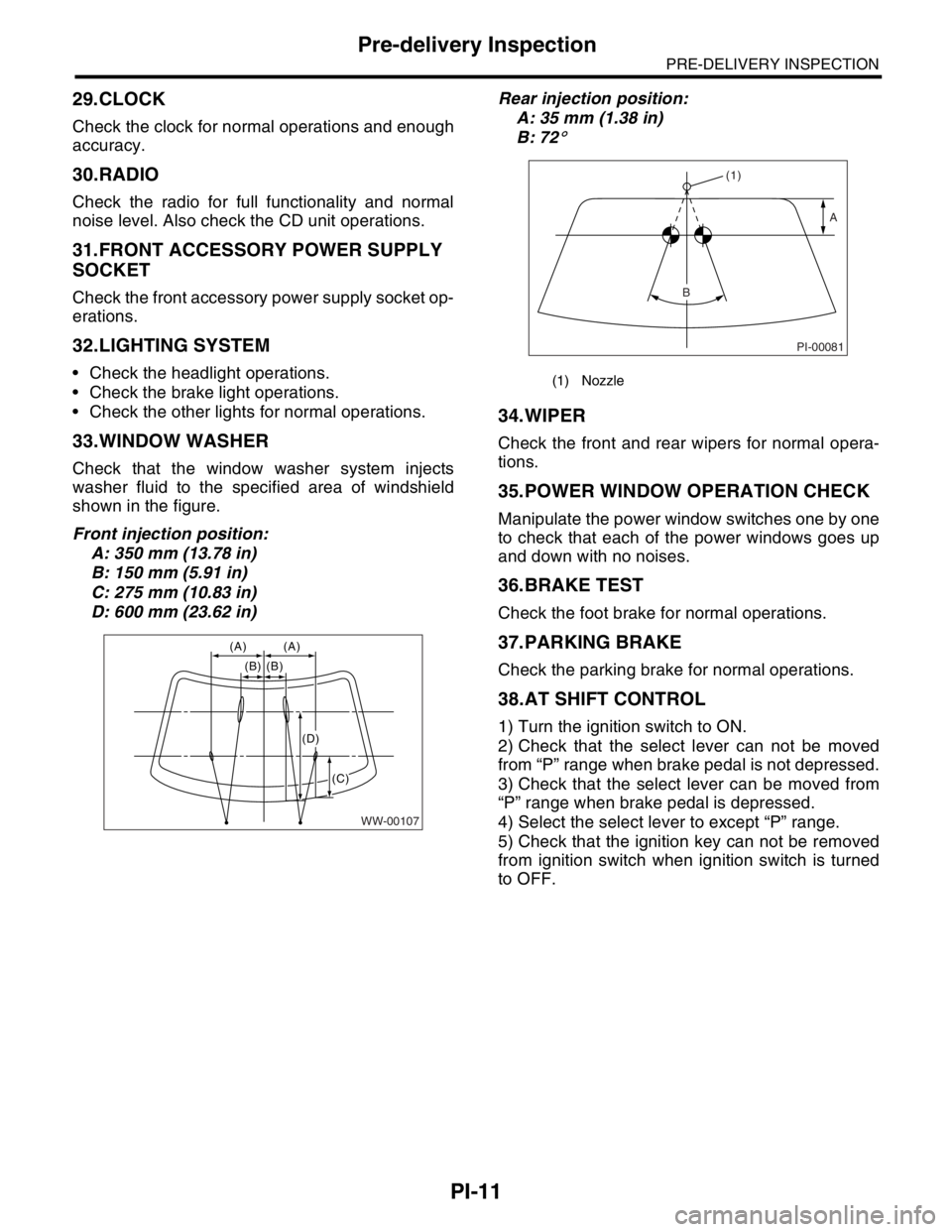
33.WINDOW WASHER
Check that the window washer system injects
washer fluid to the specified area of windshield
shown in the figure.
Front injection position:
A: 350 mm (13.78 in)
B: 150 mm (5.91 in)
C: 275 mm (10.83 in)
D: 600 mm (23.62 in)Rear injection position:
A: 35 mm (1.38 in)
B: 72
°
34.WIPER
Check the front and rear wipers for normal opera-
tions.
35.POWER WINDOW OPERATION CHECK
Manipulate the power window switches one by one
to check that each of the power windows goes up
and down with no noises.
36.BRAKE TEST
Check the foot brake for normal operations.
37.PARKING BRAKE
Check the parking brake for normal operations.
38.AT SHIFT CONTROL
1) Turn the ignition switch to ON.
2) Check that the select lever can not be moved
from “P” range when brake pedal is not depressed.
3) Check that the select lever can be moved from
“P” range when brake pedal is depressed.
4) Select the select lever to except “P” range.
5) Check that the ignition key can not be removed
from ignition switch when ignition switch is turned
to OFF.
WW-00107
(A) (A)
(B) (B)
(C)
(D)
(1) Nozzle
PI-00081
(1)
A
B
Page 744 of 2870
PM-7
PERIODIC MAINTENANCE SERVICE
Engine Oil
3. Engine Oil
A: REPLACEMENT
1) Open the engine oil filler cap for quick draining of
the engine oil.
2) Remove six clips securing service hole cover.
3) Turn the service hole cover counterclockwise.4) Drain the engine oil by loosening engine oil drain
plug.
5) Replace the drain plug gasket with a new one.
6) Tighten the engine oil drain plug after draining
engine oil.
Tightening torque:
44 N·m (4.5 kgf-m, 33 ft-lb)
(A) Oil level gauge
(B) Engine oil filler cap
PM-00155
(A)(B)
LU-00005
LU-00006
(A) Engine oil drain plug
(B) Engine oil filter
(A) Engine oil drain plug
(B) Engine oil filter
LU-00007
(B)
(A)
LU-00007
(B)
(A)