2004 SUBARU FORESTER brakes
[x] Cancel search: brakesPage 693 of 2870

SPC-4
SPECIFICATION
Forester
F: SUSPENSION
G: BRAKE
★: RHD model
H: TIRE
I: CAPACITY
★1: With oil pump★2: MT model with oil cooler Included★3: Model with ATF warmer Front Macpherson strut type, Independent, Coil spring
Rear Dual-link type, Independent, Coil spring
Model 2.0 L Non-turbo, 2.5 L Non-turbo
2.0 L Turbo, 2.5 L Non-turbo
★, 2.5 L Non-turbo
Service brake system Dual circuit hydraulic with vacuum suspended power unit
Front Ventilated disc brake
Rear Drum brake Disc brake
Parking brake Mechanical on rear brakes
Rim size 15×6J 16×6 1/2J
Tire size 205/70 R15 95H 215/60 R16 95V, P215/60 R16 94H
Type Steel belted radial, Tubeless
Model 2.0 L Non-turbo 2.0 L Turbo 2.5 L Non-turbo 2.5 L Turbo
Tr a n s m i s s i o n 5 M T 4 AT 5 M T 4 AT 5 M T 4 AT 5 M T 4 AT
Fuel tank2 (US gal, Imp gal) 60 (15.9, 13.2)
Engine oil
(When
replacing)2 (US qt, Imp qt) Approx. 4.0 (4.2, 3.5)
Tr a n s m i s -
sion gear oil2 (US qt, Imp qt)4.0
(4.2, 3.5)—3.5
(3.7, 3.1),
3.9
(4.1, 3.4)
★1
—4.0
(4.2, 3.5)—3.5
(3.7, 3.1)—
AT F2 (US qt, Imp qt) —8.4
(8.9, 7.4)—9.3
(9.8, 8.2)—9.3
(9.8, 8.2)—9.3
(9.8, 8.2)
Front differ-
ential gear
oil2 (US qt, Imp qt) —1.2
(1.3, 1.1)—1.2
(1.3, 1.1)—1.2
(1.3, 1.1)—1.2
(1.3, 1.1)
Rear differ-
ential gear
oil2 (US qt, Imp qt) 0.8 (0.8, 0.6)
Pow er
steering
fluid2 (US qt, Imp qt) 0.7 (0.7, 0.6)
Engine
coolant2 (US qt, Imp qt)6.6
(7.0, 5.8)6.5
(6.9, 5.7),
6.9
(7.3, 6.1)
★3
7.4
(7.8, 6.5)7.3
(7.7, 6.4)
★2
6.9
(7.3, 6.1)6.8
(7.2, 6.0)7.4
(7.8, 6.5)7.3
(7.7, 6.4)
Page 768 of 2870
PM-31
PERIODIC MAINTENANCE SERVICE
Brake Line
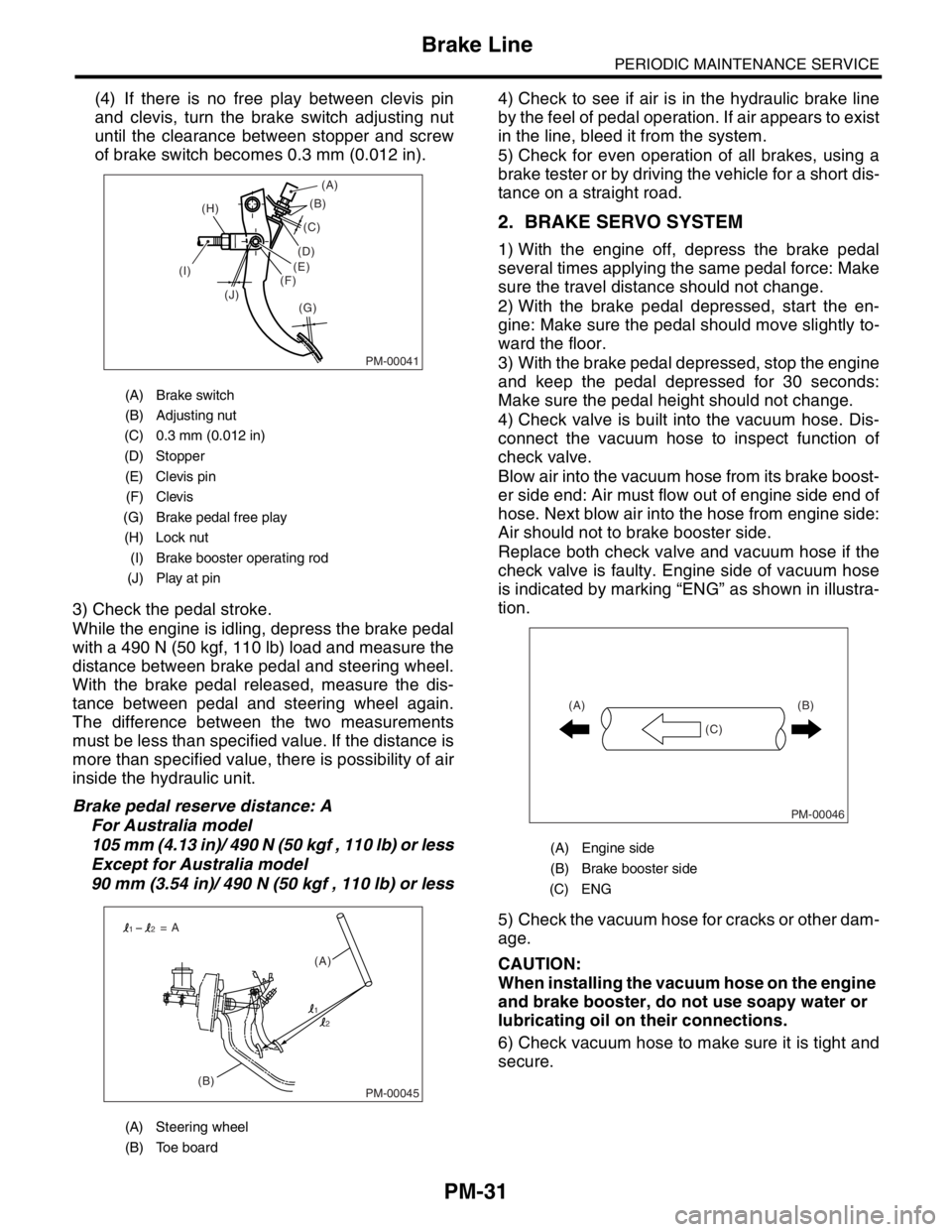
(4) If there is no free play between clevis pin
and clevis, turn the brake switch adjusting nut
until the clearance between stopper and screw
of brake switch becomes 0.3 mm (0.012 in).
3) Check the pedal stroke.
While the engine is idling, depress the brake pedal
with a 490 N (50 kgf, 110 lb) load and measure the
distance between brake pedal and steering wheel.
With the brake pedal released, measure the dis-
tance between pedal and steering wheel again.
The difference between the two measurements
must be less than specified value. If the distance is
more than specified value, there is possibility of air
inside the hydraulic unit.
Brake pedal reserve distance: A
For Australia model
105 mm (4.13 in)/ 490 N (50 kgf , 110 lb) or less
Except for Australia model
90 mm (3.54 in)/ 490 N (50 kgf , 110 lb) or less4) Check to see if air is in the hydraulic brake line
by the feel of pedal operation. If air appears to exist
in the line, bleed it from the system.
5) Check for even operation of all brakes, using a
brake tester or by driving the vehicle for a short dis-
tance on a straight road.
2. BRAKE SERVO SYSTEM
1) With the engine off, depress the brake pedal
several times applying the same pedal force: Make
sure the travel distance should not change.
2) With the brake pedal depressed, start the en-
gine: Make sure the pedal should move slightly to-
ward the floor.
3) With the brake pedal depressed, stop the engine
and keep the pedal depressed for 30 seconds:
Make sure the pedal height should not change.
4) Check valve is built into the vacuum hose. Dis-
connect the vacuum hose to inspect function of
check valve.
Blow air into the vacuum hose from its brake boost-
er side end: Air must flow out of engine side end of
hose. Next blow air into the hose from engine side:
Air should not to brake booster side.
Replace both check valve and vacuum hose if the
check valve is faulty. Engine side of vacuum hose
is indicated by marking “ENG” as shown in illustra-
tion.
5) Check the vacuum hose for cracks or other dam-
age.
CAUTION:
When installing the vacuum hose on the engine
and brake booster, do not use soapy water or
lubricating oil on their connections.
6) Check vacuum hose to make sure it is tight and
secure.
(A) Brake switch
(B) Adjusting nut
(C) 0.3 mm (0.012 in)
(D) Stopper
(E) Clevis pin
(F) Clevis
(G) Brake pedal free play
(H) Lock nut
(I) Brake booster operating rod
(J) Play at pin
(A) Steering wheel
(B) Toe board
PM-00041
(B)
(G) (H)
(I)
(J)(C)
(D)
(E)
(F)(A)
PM-00045(B)(A) = A
1
12
2
(A) Engine side
(B) Brake booster side
(C) ENG
PM-00046
(B)
(C) (A)
Page 769 of 2870

PM-32
PERIODIC MAINTENANCE SERVICE
Brake Fluid
19.Brake Fluid
A: REPLACEMENT
1) Lift-up the vehicle.
2) Remove both front and rear wheels.
3) Draw out the brake fluid from master cylinder
with syringe.
4) Refill the reservoir tank with recommended
brake fluid.
Recommended brake fluid:
FMVSS No. 116, fresh DOT3 or DOT4 brake
fluid
CAUTION:
Avoid mixing different brands of brake fluid
to prevent degrading the quality of the fluid.
Be careful not to allow dirt or dust to get into
the reservoir tank.
Bleeding sequence (1) → (2) → (3) → (4)
5) Install one end of a vinyl tube onto the air bleeder
and insert the other end of the tube into a container
to collect the brake fluid.
CAUTION:
Cover the bleeder with waste cloth, when
loosening it, to prevent brake fluid from being
splashed over surrounding parts. During the bleeding operation, keep the
brake reservoir tank filled with brake fluid to
eliminate entry of air.
The brake pedal operating must be very slow.
For convenience and safety, two people
should do the work.
NOTE:
The amount of brake fluid required is approx. 500
m2 (16.9 US fl oz, 17.6 Imp fl oz) for total brake
system.
6) Instruct your co-worker to depress the brake
pedal slowly two or three times and then hold it de-
pressed.
7) Loosen the bleeder screw approx. 1/4 turn until a
small amount of brake fluid drains into container,
and then quickly tighten the screw.
8) Repeat steps 6) and 7) above until there are no
air bubbles in the drained brake fluid and new fluid
flows through vinyl tube.
NOTE:
Add brake fluid as necessary while performing the
air bleed operation, in order to prevent the tank
from running short of brake fluid.
9) After completing the bleeding operation, hold
brake pedal depressed and tighten the bleeder
screw and install bleeder cap.
Tightening torque:
8 N·m (0.8 kgf-m, 5.8 ft-lb)
10) Bleed air from each wheel cylinder by following
the previous 5 steps.
11) Depress the brake pedal with a force of approx.
294 N (30 kgf, 66 lb) and hold it there for approx. 20
seconds. At this time check the pedal to see if it
makes any unusual movement. Visually inspect the
bleeder screws and brake pipe joints to make sure
that there is no fluid leakage.
12) Install the wheels, and drive the vehicle for a
short distance between 2 to 3 km (1 to 2 miles) to
make sure that brakes are operating properly.
(1) Front right
(2) Rear left
(3) Front left
(4) Rear right
(5) Secondary
(6) Primary
(1) (4)
(2) (3) (5) (6)
PM-00047
PM-00048
Page 1137 of 2870
EN(H4SO)-39
ENGINE (DIAGNOSTIC)
Inspection Mode
1. PREPARATION FOR THE INSPECTION
MODE
1) Check battery voltage is more than 12 V and fuel
remains half [20 — 402 (5.3 — 10.6 US gal, 4.4 —
8.8 Imp gal)].
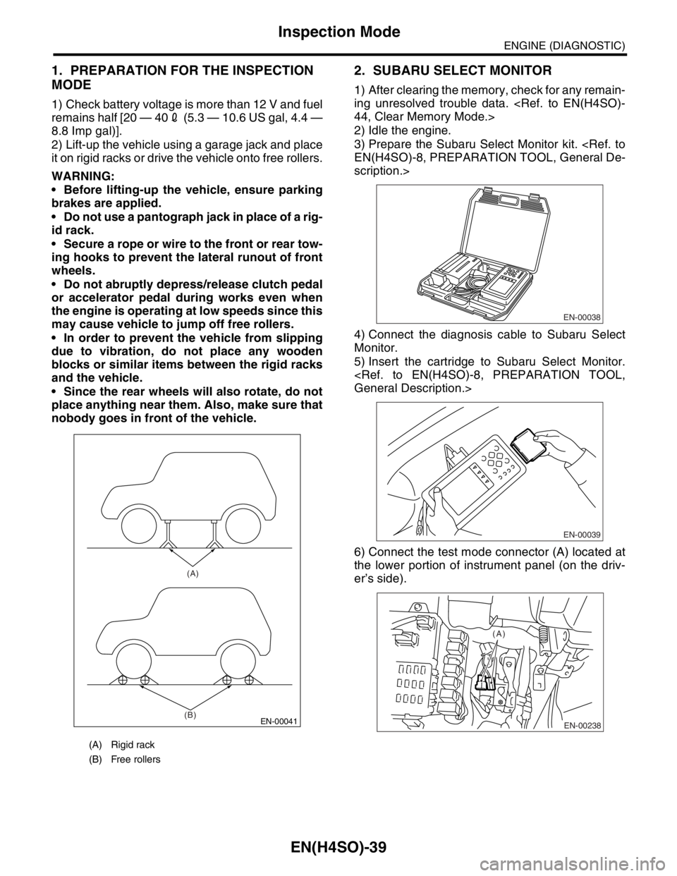
2) Lift-up the vehicle using a garage jack and place
it on rigid racks or drive the vehicle onto free rollers.
WARNING:
Before lifting-up the vehicle, ensure parking
brakes are applied.
Do not use a pantograph jack in place of a rig-
id rack.
Secure a rope or wire to the front or rear tow-
ing hooks to prevent the lateral runout of front
wheels.
Do not abruptly depress/release clutch pedal
or accelerator pedal during works even when
the engine is operating at low speeds since this
may cause vehicle to jump off free rollers.
In order to prevent the vehicle from slipping
due to vibration, do not place any wooden
blocks or similar items between the rigid racks
and the vehicle.
Since the rear wheels will also rotate, do not
place anything near them. Also, make sure that
nobody goes in front of the vehicle.
2. SUBARU SELECT MONITOR
1) After clearing the memory, check for any remain-
ing unresolved trouble data.
2) Idle the engine.
3) Prepare the Subaru Select Monitor kit.
scription.>
4) Connect the diagnosis cable to Subaru Select
Monitor.
5) Insert the cartridge to Subaru Select Monitor.
6) Connect the test mode connector (A) located at
the lower portion of instrument panel (on the driv-
er’s side).
(A) Rigid rack
(B) Free rollers
EN-00041
(A)
(B)
EN-00038
EN-00039
EN-00238
(A)
Page 1672 of 2870
EN(H4DOTC)-42
ENGINE (DIAGNOSTIC)
Inspection Mode
1. PREPARATION FOR THE INSPECTION
MODE
1) Check battery voltage is more than 12 V and fuel
remains half [20 to 402 (5.3 to 10.6 US gal, 4.4 to
8.8 Imp gal)].
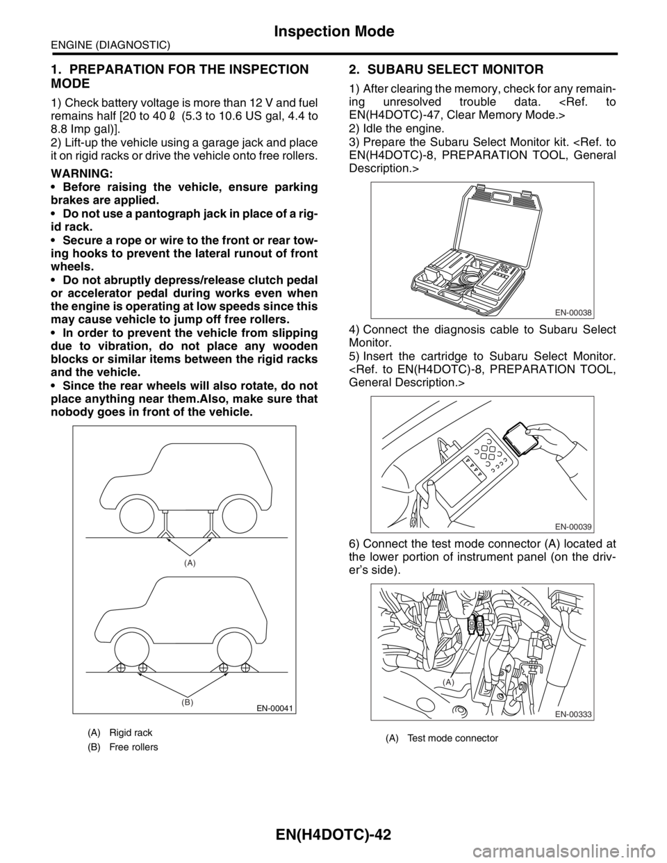
2) Lift-up the vehicle using a garage jack and place
it on rigid racks or drive the vehicle onto free rollers.
WARNING:
Before raising the vehicle, ensure parking
brakes are applied.
Do not use a pantograph jack in place of a rig-
id rack.
Secure a rope or wire to the front or rear tow-
ing hooks to prevent the lateral runout of front
wheels.
Do not abruptly depress/release clutch pedal
or accelerator pedal during works even when
the engine is operating at low speeds since this
may cause vehicle to jump off free rollers.
In order to prevent the vehicle from slipping
due to vibration, do not place any wooden
blocks or similar items between the rigid racks
and the vehicle.
Since the rear wheels will also rotate, do not
place anything near them.Also, make sure that
nobody goes in front of the vehicle.
2. SUBARU SELECT MONITOR
1) After clearing the memory, check for any remain-
ing unresolved trouble data.
2) Idle the engine.
3) Prepare the Subaru Select Monitor kit.
Description.>
4) Connect the diagnosis cable to Subaru Select
Monitor.
5) Insert the cartridge to Subaru Select Monitor.
6) Connect the test mode connector (A) located at
the lower portion of instrument panel (on the driv-
er’s side).
(A) Rigid rack
(B) Free rollers
EN-00041
(A)
(B)
(A) Test mode connector
EN-00038
EN-00039
EN-00333
(A)
Page 2061 of 2870
EN(H4DOTC 2.5)-37
ENGINE (DIAGNOSTIC)
Inspection Mode
1. PREPARATION FOR THE INSPECTION
MODE
1) Check battery voltage is more than 12 V and fuel
remains half [20 — 402 (5.3 — 10.6 US gal, 4.4 —
8.8 Imp gal)].
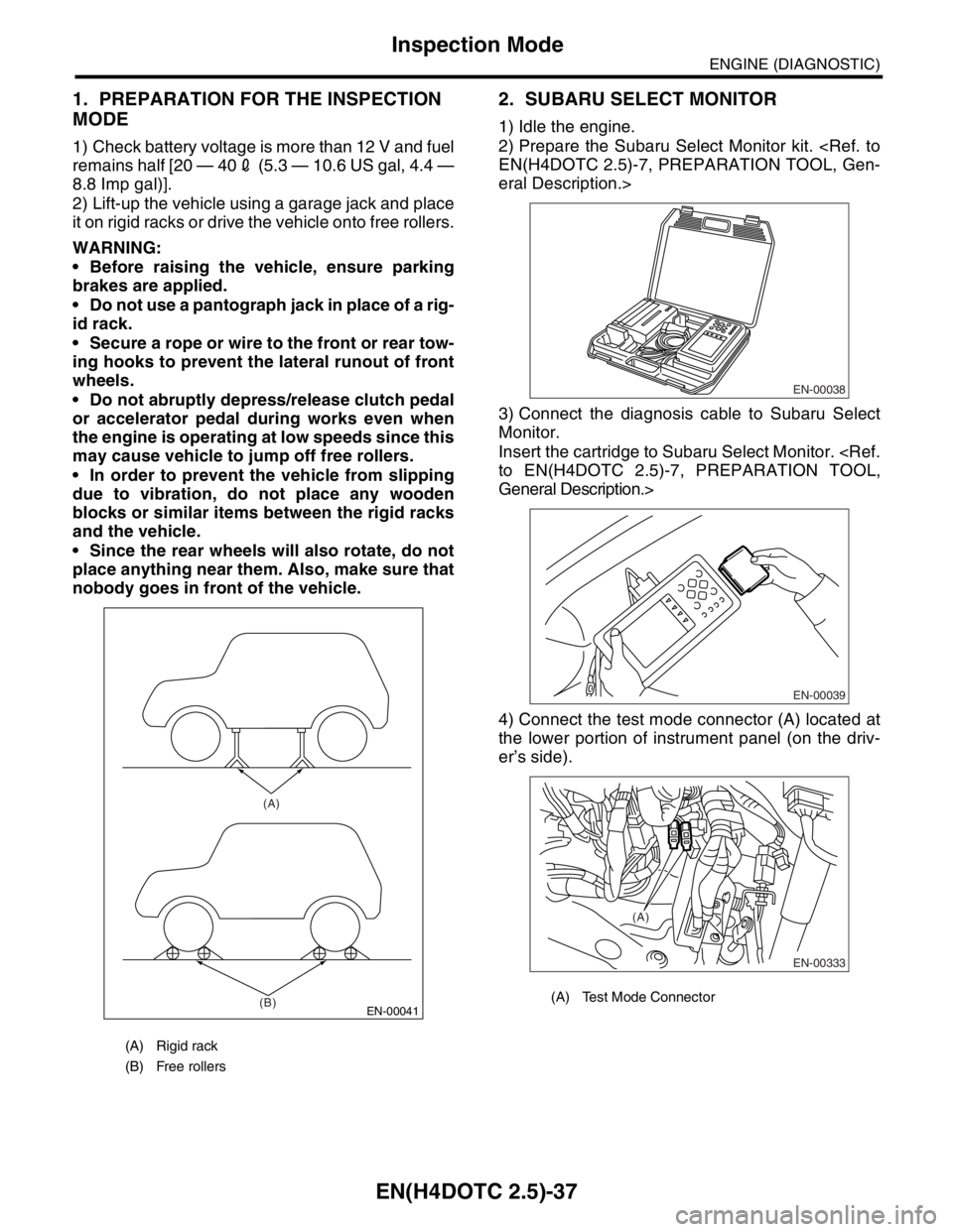
2) Lift-up the vehicle using a garage jack and place
it on rigid racks or drive the vehicle onto free rollers.
WARNING:
Before raising the vehicle, ensure parking
brakes are applied.
Do not use a pantograph jack in place of a rig-
id rack.
Secure a rope or wire to the front or rear tow-
ing hooks to prevent the lateral runout of front
wheels.
Do not abruptly depress/release clutch pedal
or accelerator pedal during works even when
the engine is operating at low speeds since this
may cause vehicle to jump off free rollers.
In order to prevent the vehicle from slipping
due to vibration, do not place any wooden
blocks or similar items between the rigid racks
and the vehicle.
Since the rear wheels will also rotate, do not
place anything near them. Also, make sure that
nobody goes in front of the vehicle.
2. SUBARU SELECT MONITOR
1) Idle the engine.
2) Prepare the Subaru Select Monitor kit.
eral Description.>
3) Connect the diagnosis cable to Subaru Select
Monitor.
Insert the cartridge to Subaru Select Monitor.
General Description.>
4) Connect the test mode connector (A) located at
the lower portion of instrument panel (on the driv-
er’s side).
(A) Rigid rack
(B) Free rollers
EN-00041
(A)
(B)
(A) Test Mode Connector
EN-00038
EN-00039
EN-00333
(A)
Page 2344 of 2870

4AT-32
AUTOMATIC TRANSMISSION
Road Test
4. Road Test
A: INSPECTION
1. GENERAL PRECAUTION
Road tests should be conducted to properly diag-
nose the condition of the automatic transmission.
NOTE:
When performing the test, do not exceed posted
speed limit.
2. D RANGE SHIFT FUNCTION
Check shifting between 1st ←→ 2nd ←→ 3rd ←→
4th while driving on normal city streets.
3. D RANGE SHIFT SHOCK
Check the shock level when shifting up during nor-
mal driving.
4. KICK-DOWN FUNCTION
Check kick-down for each gear. Also check the
kick-down shock level.
5. ENGINE BRAKE OPERATION
Check the 3rd gear engine brake when shifting
down from D ←→ 3rd range while driving in 4th
gear of D range [50 — 60 km/h (31 — 37 MPH)].
Check the 2nd gear engine brake when shifting
between 3rd ←→ 2nd range while driving in the 3rd
range of 3rd gear [40 — 50 km/h (25 — 31 MPH)].
Check the 1st gear engine brake when shifting
between 2nd ←→ 1st range while driving in the 2nd
range of 2nd gear [20 — 30 km/h (12 — 19 MPH)].
6. LOCK-UP FUNCTION
Check that rpm does not change sharply when
the axle pedal is lightly depressed when driving on
flat roads at 60 km/h (37 MPH).
Check slip lock-up with following procedure.
Subaru Select Monitor is needed for checking (EC,
EK model).
Before start checking, check that the DTC is not ex-
isted using Subaru Select Monitor. When the DTC
is existed, perform the collective action with DTC
and check that the DTC is not existed again, and
then start the checking.
1) The check performed on flat and straight road or
free roller.
NOTE:
Slip lock-up does not operate when the vehicle is
lifted up, because of not occurring surface resis-
tance.
Also checking on the free roller, check with de-
pressing foot brake lightly to make the checking
easier, because the surface resistance will be defi-
cient2) Connect the Subaru Select Monitor.
3) Check ATF temperature using Subaru Select
Monitor.
NOTE:
ATF temperature is between 50 — 100°C (122
— 212°F).
When the temperature is low, warm-up the ATF
by running the vehicle or etc.
4) Start the engine, and make the lock-up duty be
able to read on data display of Subaru Select Mon-
itor.
5) 35 — 40 Drive the vehicle at a constant speed of
35 — 40 km/h (22 — 25 MPH).
6) Read the lock-up duty while vehicle is running.
Standard value:
25 — 45%
NOTE:
On the free roller, the value sometimes lowers.
Slip lock-up control is not operating when the
lock-up duty is less than 5%, or when the lock-up
duty goes down immediately after starts rise. On
these cases, improper ATF or deterioration of ATF
may be the cause. Check the amount of ATF or re-
place them, and then recheck it.
7. P RANGE OPERATION
Stop the vehicle on an uphill grade of 5% or more
and shift to “P” range. Check that the vehicle does
not move when the parking brake is released.
8. NOISE AND VIBRATION
Check for unusual sounds and vibration while driv-
ing and during shifting.
9. CLIMBING CONTROL FUNCTION
Check that the gear remains in 3rd when going
up a grade.
Check that the gear remains in 3rd when apply-
ing the brakes while going down a grade.
10.TRANSFER CLUTCH
Check tight corner braking when the vehicle started
with steering fully turned.
11.OIL LEAKS
After the driving test, inspect for oil leaks.
Page 2348 of 2870
4AT-36
AUTOMATIC TRANSMISSION
Line Pressure Test
7. Line Pressure Test
A: MEASUREMENT
NOTE:
If the clutch or the brake shows a sign of slippage or
shifting sensation is not correct, the line pressure
should be checked.
Excessive shocks during upshifting or shifting
takes place at a higher point than under normal cir-
cumstances, may be due to the line pressure being
too high.
Slippage or inability to operate the vehicle may,
in most cases, be due to insufficient oil pressure for
the operation of the clutch, brake or control valve.
1) Line pressure measurement (under no load):
(1) Before measuring line pressure, jack-up all
wheels.
(2) Maintain the temperature of ATF at approx.
70 — 80°C (158 — 176°F) during measurement.
(ATF will reach the above temperature after
idling the engine for approx. 30 minutes with the
select lever in “N” or “P”.)
2) Line pressure measurement (under heavy load):
(1) Before measuring line pressure, apply both
foot and parking brakes with all wheels chocked
(Same as for “stall” test conditions).
(2) Measure the line pressure when the select
lever is in “D”, “2” (HOLD switch ON) with engine
under stall conditions.
(3) Measure the line pressure within 5 seconds
after shifting the select lever to each position. (If
the line pressure needs to be measured again,
allow the engine to idle and cool it down more
than 1 minute.)
(4) Maintain the ATF temperature at approx. 70
— 80°C (158 — 176°F) during measurement.
(ATF will reach the above temperature after
idling the engine for approx. 30 minutes with the
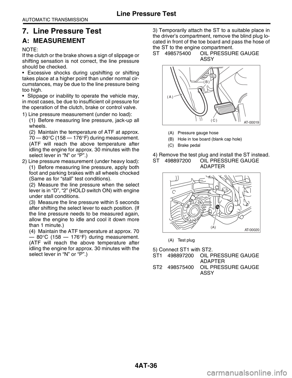
select lever in “N” or “P”.)3) Temporarily attach the ST to a suitable place in
the driver’s compartment, remove the blind plug lo-
cated in front of the toe board and pass the hose of
the ST to the engine compartment.
ST 498575400 OIL PRESSURE GAUGE
ASSY
4) Remove the test plug and install the ST instead.
ST 498897200 OIL PRESSURE GAUGE
ADAPTER
5) Connect ST1 with ST2.
ST1 498897200 OIL PRESSURE GAUGE
ADAPTER
ST2 498575400 OIL PRESSURE GAUGE
ASSY
(A) Pressure gauge hose
(B) Hole in toe board (blank cap hole)
(C) Brake pedal
(A) Test plug
AT-00019
(A)(B)
(C)
AT-00020(A)