2004 SUBARU FORESTER washer fluid
[x] Cancel search: washer fluidPage 294 of 2870

WW-6
WIPER AND WASHER SYSTEM
Wiper and Washer System
2. Wiper and Washer System
A: WIRING DIAGRAM
1. WIPER AND WASHER (FRONT)
2. WIPER AND WASHER (REAR)
B: INSPECTION
Symptom Repair order
Wiper and washers do not operate. (1) Wiper fuse (F/B No. 14, 15)
(2) Combination switch
(3) Wiper motor
(4) Wiring harness
Wipers do not operate in LO or HI. (1) Combination switch
(2) Wiper motor
(3) Wiring harness
Wipers do not operate in INT. (1) Combination switch
(2) Wiper motor
(3) Wiring harness
Washer motor does not operate. (1) Washer switch
(2) Washer motor
(3) Wiring harness
Wipers do not operate when washer switch is ON. (1) Washer motor
(2) Wiring harness
Washer fluid spray does not operate. (1) Washer motor
(2) Washer hose and nozzle
Page 308 of 2870
WW-20
WIPER AND WASHER SYSTEM
Headlight Washer
13.Headlight Washer
A: REMOVAL
1) Disconnect the ground cable from the battery.
2) Remove the front grille.
3) Remove the headlight.
4) Draw out headlight washer hose.
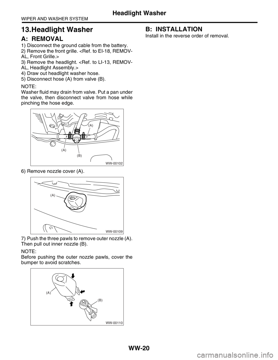
5) Disconnect hose (A) from valve (B).
NOTE:
Washer fluid may drain from valve. Put a pan under
the valve, then disconnect valve from hose while
pinching the hose edge.
6) Remove nozzle cover (A).
7) Push the three pawls to remove outer nozzle (A).
Then pull out inner nozzle (B).
NOTE:
Before pushing the outer nozzle pawls, cover the
bumper to avoid scratches.
B: INSTALLATION
Install in the reverse order of removal.
WW-00102
(B) (A)
(A)
WW-00109
(A)
WW-00110
(A)
(B)
Page 726 of 2870

PI-3
PRE-DELIVERY INSPECTION
Pre-delivery Inspection
B: PDI PROCEDURE
Follow the procedures shown in the table below.
Static Checks Just After Vehicle Receipt
Step Check point
1. Appearance check (1) If the vehicle is covered with protective coating, visually check the vehicle
body for damage and dents. If the protective coating has been removed,
visually check the body paints for small areas of damage or stains.
(2) Visually check the glass and light lenses for any damage and cracks or
excessive gaps to the body sheet metal.
(3) Visually check the plated parts for any damage.
2. Tire check (1) Check the tires for damage, abnormal conditions, and dents on the
wheels.
(2) Check the tire air pressure.
3. Fuse installation If the vehicle is about to be delivered to the customer, attach a room light
fuse.
4. Connection of air conditioner harness If the vehicle is about to be delivered to the customer, connect the air condi-
tioner harness.
5. Check the doors for lock/unlock and open/close
operations.(1) Using the key, check if the door can be locked and unlocked normally.
(2) Open and close all doors to see that there are no abnormal conditions.
6. Operation check of double lock Check that the double lock operates normally.
7. Operation check of the child safety lock system. Check the child safety lock system operates normally.
8. Check the rear gate for lock/unlock and open/
close operations.(1) Check if the rear gate can be unlocked normally from the emergency
door.
(2) Open and close the rear gate to see that there are no abnormal condi-
tions.
(3) Operate the power door locking switch to check that the rear gate is
locked and unlocked normally.
9. Operation check of fuel lid opener lock release
leverOperate the fuel lid opener to check that the fuel lid is unlocked normally.
10. Accessory check Check that the following accessories are provided:
Owner’s manual
Warranty booklet
Service booklet
Spare key
Jack
Tool set
Spare tire
11. Operation check of hood lock release system Operate the hood lock release lever to check that the hood opens normally.
12. Battery Check the battery for any abnormal conditions such as rust and trace of bat-
tery fluid leaks.
13. Brake fluid Check the fluid amount.
14. Engine oil Check the oil amount.
15. Transmission fluid (1) Check the fluid amount.
(2) For AT, check the front differential oil.
16. AT front differential oil Check the AT front differential oil amount.
17. Coolant Check the coolant amount.
18. Clutch fluid Check the clutch fluid amount.
19. Window washer fluid Check the window washer fluid amount.
20. Hood latch check Check that the hood is closed and latched securely.
21. Keyless entry system Check that the keyless entry system operates normally.
22. Security system Check that the security system operates normally.
23. Seat (1) Check the seat surfaces for smears or dirt.
(2) Check the seat installation conditions and functionality.
24. Seat belt Check the seat belt installation conditions and functionality.
25. Wheel alignment Check that the wheel alignments are properly adjusted.
Page 727 of 2870

PI-4
PRE-DELIVERY INSPECTION
Pre-delivery Inspection
Checks with the Engine Running
Dynamic Test with the Vehicle Running
Checks after Dynamic Test
Step Check point
26. Test mode connectors Test mode connectors
27. Starting condition Start the engine and check that the engine starts smoothly.
28. Exhaust system Check that the exhaust noise is normal and no leaks are found.
29. Indicator light Check that all the indicator lights operate normally.
30. Clock Check that the clock operates normally.
31. Radio Check that the radio system operates normally.
32. Front accessory power supply socket Check that the front accessory power supply socket operates normally.
33. Lighting system Check that the lighting systems operate normally.
34. Window washer Check that the window washer system operates normally.
35. Wiper Check that the wiper system operates normally.
36. Power window operation check Check the power window for correct operations.
Step Check point
37. Brake test Check that the foot brake operates normally.
38. Parking brake Check that the parking brake operates normally.
39. AT shift control Check the AT shift patterns are correct.
40. Heater & ventilation Check that the heater & ventilation system operates normally.
41. Air conditioner Check that the air conditioner operates normally.
42. Speed control Check that the speed control operates normally.
Step Check point
43. ATF level Check that the ATF level is normal.
44. Power steering fluid level Check that the power steering fluid level is normal.
45. Fluid leak check Check for fluid/oil leaks.
46. Water leak check Spray the vehicle with water and check for water leaks.
47. Appearance check 2 (1) Remove the protective coating (wrap guard).(if any)
(2) Check the body paints for damage and smears.
(3) Check the plated parts for damage and rust.
Page 732 of 2870
PI-9
PRE-DELIVERY INSPECTION
Pre-delivery Inspection
15.TRANSMISSION FLUID
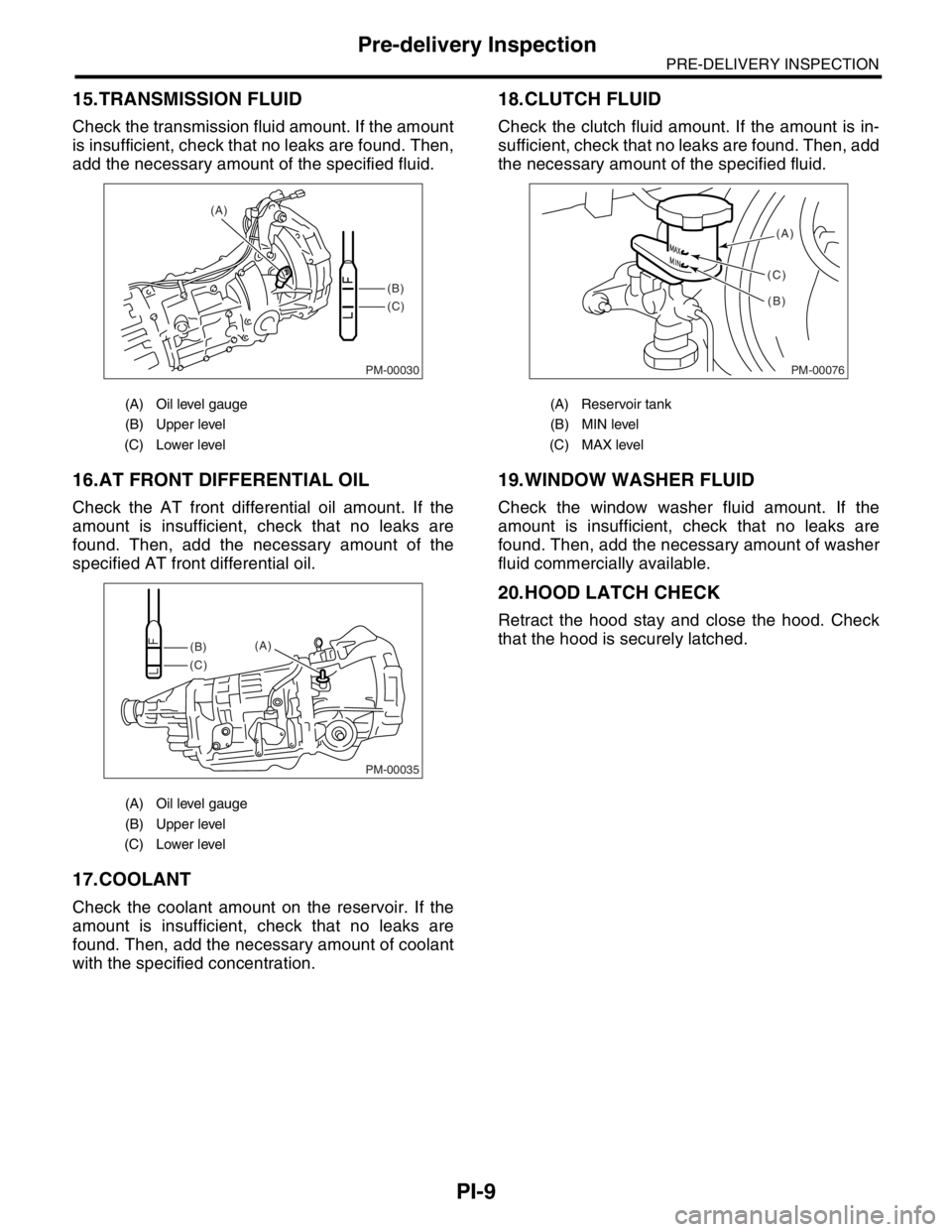
Check the transmission fluid amount. If the amount
is insufficient, check that no leaks are found. Then,
add the necessary amount of the specified fluid.
16.AT FRONT DIFFERENTIAL OIL
Check the AT front differential oil amount. If the
amount is insufficient, check that no leaks are
found. Then, add the necessary amount of the
specified AT front differential oil.
17.COOLANT
Check the coolant amount on the reservoir. If the
amount is insufficient, check that no leaks are
found. Then, add the necessary amount of coolant
with the specified concentration.
18.CLUTCH FLUID
Check the clutch fluid amount. If the amount is in-
sufficient, check that no leaks are found. Then, add
the necessary amount of the specified fluid.
19.WINDOW WASHER FLUID
Check the window washer fluid amount. If the
amount is insufficient, check that no leaks are
found. Then, add the necessary amount of washer
fluid commercially available.
20.HOOD LATCH CHECK
Retract the hood stay and close the hood. Check
that the hood is securely latched.
(A) Oil level gauge
(B) Upper level
(C) Lower level
(A) Oil level gauge
(B) Upper level
(C) Lower level
PM-00030
(B)
(C) (A)
PM-00035
(B)
(C)(A)
(A) Reservoir tank
(B) MIN level
(C) MAX level
PM-00076
(A)
(B) (C)
Page 734 of 2870
PI-11
PRE-DELIVERY INSPECTION
Pre-delivery Inspection
29.CLOCK
Check the clock for normal operations and enough
accuracy.
30.RADIO
Check the radio for full functionality and normal
noise level. Also check the CD unit operations.
31.FRONT ACCESSORY POWER SUPPLY
SOCKET
Check the front accessory power supply socket op-
erations.
32.LIGHTING SYSTEM
Check the headlight operations.
Check the brake light operations.
Check the other lights for normal operations.
33.WINDOW WASHER
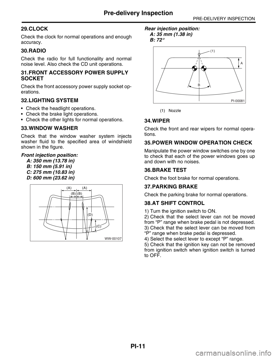
Check that the window washer system injects
washer fluid to the specified area of windshield
shown in the figure.
Front injection position:
A: 350 mm (13.78 in)
B: 150 mm (5.91 in)
C: 275 mm (10.83 in)
D: 600 mm (23.62 in)Rear injection position:
A: 35 mm (1.38 in)
B: 72
°
34.WIPER
Check the front and rear wipers for normal opera-
tions.
35.POWER WINDOW OPERATION CHECK
Manipulate the power window switches one by one
to check that each of the power windows goes up
and down with no noises.
36.BRAKE TEST
Check the foot brake for normal operations.
37.PARKING BRAKE
Check the parking brake for normal operations.
38.AT SHIFT CONTROL
1) Turn the ignition switch to ON.
2) Check that the select lever can not be moved
from “P” range when brake pedal is not depressed.
3) Check that the select lever can be moved from
“P” range when brake pedal is depressed.
4) Select the select lever to except “P” range.
5) Check that the ignition key can not be removed
from ignition switch when ignition switch is turned
to OFF.
WW-00107
(A) (A)
(B) (B)
(C)
(D)
(1) Nozzle
PI-00081
(1)
A
B
Page 2394 of 2870
4AT-81
AUTOMATIC TRANSMISSION
ATF Cooler Pipe and Hose
B: INSTALLATION
1. EXCEPT WITH ATF COOLER MODEL
(WITH WARMER FUNCTION)
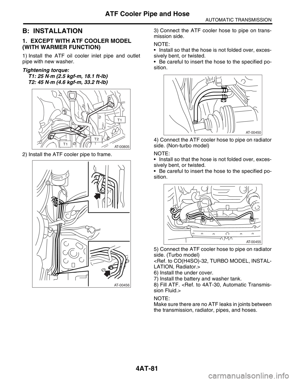
1) Install the ATF oil cooler inlet pipe and outlet
pipe with new washer.
Tightening torque:
T1: 25 N
⋅m (2.5 kgf-m, 18.1 ft-lb)
T2: 45 N
⋅m (4.6 kgf-m, 33.2 ft-lb)
2) Install the ATF cooler pipe to frame.3) Connect the ATF cooler hose to pipe on trans-
mission side.
NOTE:
Install so that the hose is not folded over, exces-
sively bent, or twisted.
Be careful to insert the hose to the specified po-
sition.
4) Connect the ATF cooler hose to pipe on radiator
side. (Non-turbo model)
NOTE:
Install so that the hose is not folded over, exces-
sively bent, or twisted.
Be careful to insert the hose to the specified po-
sition.
5) Connect the ATF cooler hose to pipe on radiator
side. (Turbo model)
6) Install the under cover.
7) Install the battery and washer tank.
8) Fill ATF.
NOTE:
Make sure there are no ATF leaks in joints between
the transmission, radiator, pipes, and hoses.
AT-00805
T1
T1
T2
AT-00456
AT-00450
AT-00455
Page 2854 of 2870
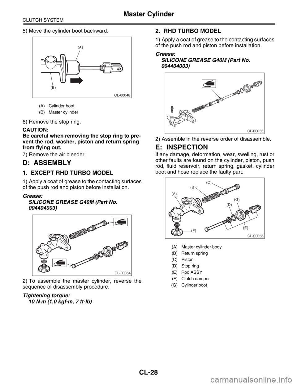
CL-28
CLUTCH SYSTEM
Master Cylinder
5) Move the cylinder boot backward.
6) Remove the stop ring.
CAUTION:
Be careful when removing the stop ring to pre-
vent the rod, washer, piston and return spring
from flying out.
7) Remove the air bleeder.
D: ASSEMBLY
1. EXCEPT RHD TURBO MODEL
1) Apply a coat of grease to the contacting surfaces
of the push rod and piston before installation.
Grease:
SILICONE GREASE G40M (Part No.
004404003)
2) To assemble the master cylinder, reverse the
sequence of disassembly procedure.
Tightening torque:
10 N
⋅m (1.0 kgf-m, 7 ft-lb)
2. RHD TURBO MODEL
1) Apply a coat of grease to the contacting surfaces
of the push rod and piston before installation.
Grease:
SILICONE GREASE G40M (Part No.
004404003)
2) Assemble in the reverse order of disassemble.
E: INSPECTION
If any damage, deformation, wear, swelling, rust or
other faults are found on the cylinder, piston, push
rod, fluid reservoir, return spring, gasket, cylinder
boot and hose replace the faulty part.
(A) Cylinder boot
(B) Master cylinder
CL-00048
(A)
(B)
CL-00054
(A) Master cylinder body
(B) Return spring
(C) Piston
(D) Stop ring
(E) Rod ASSY
(F) Clutch damper
(G) Cylinder boot
CL-00055
CL-00056
(B)
(C)
(D)
(E) (A)
(F)
(G)