2004 SUBARU FORESTER clock
[x] Cancel search: clockPage 746 of 2870
PM-9
PERIODIC MAINTENANCE SERVICE
Engine Oil Filter
4. Engine Oil Filter
A: REPLACEMENT
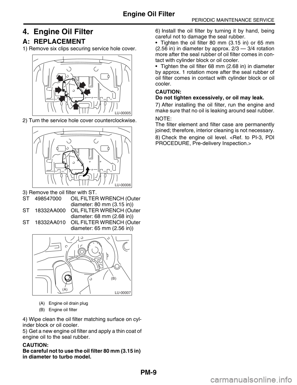
1) Remove six clips securing service hole cover.
2) Turn the service hole cover counterclockwise.
3) Remove the oil filter with ST.
ST 498547000 OIL FILTER WRENCH (Outer
diameter: 80 mm (3.15 in))
ST 18332AA000 OIL FILTER WRENCH (Outer
diameter: 68 mm (2.68 in))
ST 18332AA010 OIL FILTER WRENCH (Outer
diameter: 65 mm (2.56 in))
4) Wipe clean the oil filter matching surface on cyl-
inder block or oil cooler.
5) Get a new engine oil filter and apply a thin coat of
engine oil to the seal rubber.
CAUTION:
Be careful not to use the oil filter 80 mm (3.15 in)
in diameter to turbo model.6) Install the oil filter by turning it by hand, being
careful not to damage the seal rubber.
Tighten the oil filter 80 mm (3.15 in) or 65 mm
(2.56 in) in diameter by approx. 2/3 — 3/4 rotation
more after the seal rubber of oil filter comes in con-
tact with cylinder block or oil cooler.
Tighten the oil filter 68 mm (2.68 in) in diameter
by approx. 1 rotation more after the seal rubber of
oil filter comes in contact with cylinder block or oil
cooler.
CAUTION:
Do not tighten excessively, or oil may leak.
7) After installing the oil filter, run the engine and
make sure that no oil is leaking around seal rubber.
NOTE:
The filter element and filter case are permanently
joined; therefore, interior cleaning is not necessary.
8) Check the engine oil level.
(A) Engine oil drain plug
(B) Engine oil filter
LU-00005
LU-00006
LU-00007
(B)
(A)
Page 900 of 2870
ME(H4SO)-31
MECHANICAL
Valve Clearance
8. Valve Clearance
A: INSPECTION
NOTE:
Inspection and adjustment of the valve clearance
should be performed while engine is cold.
1) Set the vehicle on a lift.
2) Lift-up the vehicle.
3) Remove the under cover.
4) Lower the vehicle.
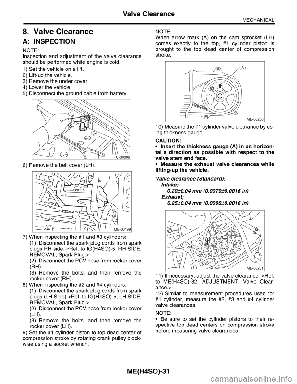
5) Disconnect the ground cable from battery.
6) Remove the belt cover (LH).
7) When inspecting the #1 and #3 cylinders:
(1) Disconnect the spark plug cords from spark
plugs RH side.
(2) Disconnect the PCV hose from rocker cover
(RH).
(3) Remove the bolts, and then remove the
rocker cover (RH).
8) When inspecting the #2 and #4 cylinders:
(1) Disconnect the spark plug cords from spark
plugs (LH Side)
(2) Disconnect the PCV hose from rocker cover
(LH).
(3) Remove the bolts, and then remove the
rocker cover (LH).
9) Set the #1 cylinder piston to top dead center of
compression stroke by rotating crank pulley clock-
wise using a socket wrench.NOTE:
When arrow mark (A) on the cam sprocket (LH)
comes exactly to the top, #1 cylinder piston is
brought to the top dead center of compression
stroke.
10) Measure the #1 cylinder valve clearance by us-
ing thickness gauge.
CAUTION:
Insert the thickness gauge (A) in as horizon-
tal a direction as possible with respect to the
valve stem end face.
Measure the exhaust valve clearances while
lifting-up the vehicle.
Valve clearance (Standard):
Intake;
0.20
±0.04 mm (0.0079±0.0016 in)
Exhaust;
0.25
±0.04 mm (0.0098±0.0016 in)
11) If necessary, adjust the valve clearance.
ance.>
12) Similar to measurement procedures used for
#1 cylinder, measure the #2, #3 and #4 cylinder
valve clearances.
NOTE:
Be sure to set the cylinder pistons to their re-
spective top dead centers on compression stroke
before measuring valve clearances.
FU-00009
ME-00199
ME-00200
(A)
ME-00201
(A)
Page 901 of 2870
ME(H4SO)-32
MECHANICAL
Valve Clearance
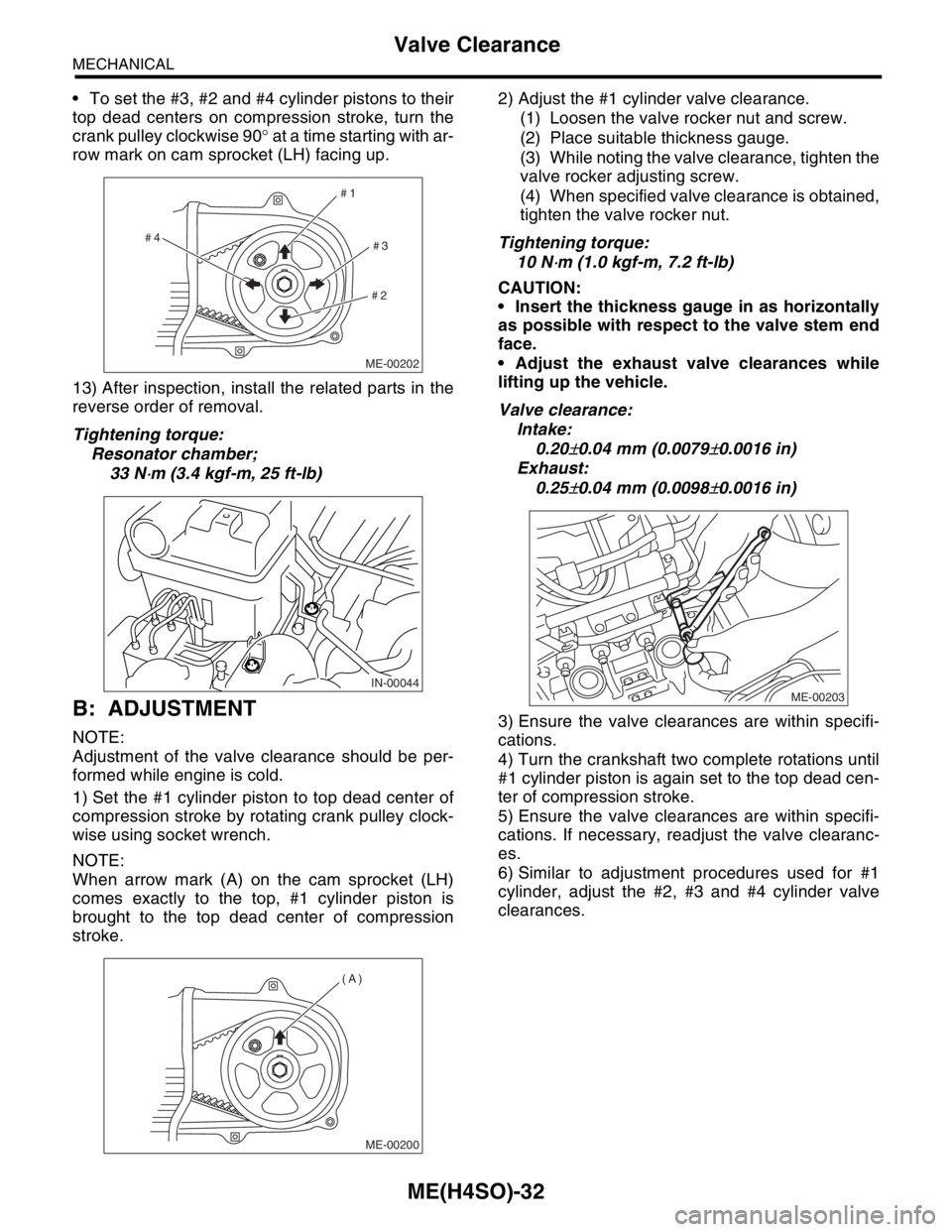
To set the #3, #2 and #4 cylinder pistons to their
top dead centers on compression stroke, turn the
crank pulley clockwise 90° at a time starting with ar-
row mark on cam sprocket (LH) facing up.
13) After inspection, install the related parts in the
reverse order of removal.
Tightening torque:
Resonator chamber;
33 N
⋅m (3.4 kgf-m, 25 ft-lb)
B: ADJUSTMENT
NOTE:
Adjustment of the valve clearance should be per-
formed while engine is cold.
1) Set the #1 cylinder piston to top dead center of
compression stroke by rotating crank pulley clock-
wise using socket wrench.
NOTE:
When arrow mark (A) on the cam sprocket (LH)
comes exactly to the top, #1 cylinder piston is
brought to the top dead center of compression
stroke.2) Adjust the #1 cylinder valve clearance.
(1) Loosen the valve rocker nut and screw.
(2) Place suitable thickness gauge.
(3) While noting the valve clearance, tighten the
valve rocker adjusting screw.
(4) When specified valve clearance is obtained,
tighten the valve rocker nut.
Tightening torque:
10 N
⋅m (1.0 kgf-m, 7.2 ft-lb)
CAUTION:
Insert the thickness gauge in as horizontally
as possible with respect to the valve stem end
face.
Adjust the exhaust valve clearances while
lifting up the vehicle.
Valve clearance:
Intake:
0.20
±0.04 mm (0.0079±0.0016 in)
Exhaust:
0.25
±0.04 mm (0.0098±0.0016 in)
3) Ensure the valve clearances are within specifi-
cations.
4) Turn the crankshaft two complete rotations until
#1 cylinder piston is again set to the top dead cen-
ter of compression stroke.
5) Ensure the valve clearances are within specifi-
cations. If necessary, readjust the valve clearanc-
es.
6) Similar to adjustment procedures used for #1
cylinder, adjust the #2, #3 and #4 cylinder valve
clearances.
ME-00202
#1
#2#3 #4
IN-00044
ME-00200
(A)
ME-00203
Page 902 of 2870
ME(H4SO)-33
MECHANICAL
Valve Clearance
NOTE:
Be sure to set the cylinder pistons to their re-
spective top dead centers on compression stroke
before adjusting valve clearances.
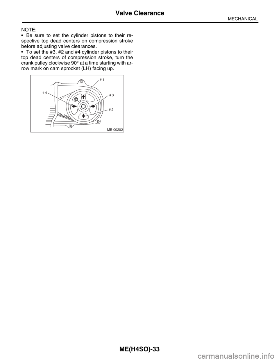
To set the #3, #2 and #4 cylinder pistons to their
top dead centers of compression stroke, turn the
crank pulley clockwise 90° at a time starting with ar-
row mark on cam sprocket (LH) facing up.
ME-00202
#1
#2#3 #4
Page 938 of 2870
ME(H4SO)-67
MECHANICAL
Cylinder Head
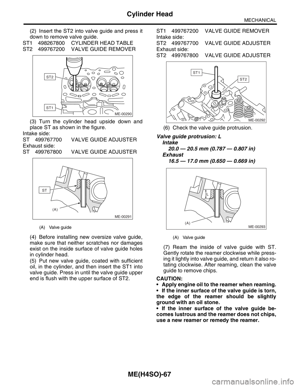
(2) Insert the ST2 into valve guide and press it
down to remove valve guide.
ST1 498267800 CYLINDER HEAD TABLE
ST2 499767200 VALVE GUIDE REMOVER
(3) Turn the cylinder head upside down and
place ST as shown in the figure.
Intake side:
ST 499767700 VALVE GUIDE ADJUSTER
Exhaust side:
ST 499767800 VALVE GUIDE ADJUSTER
(4) Before installing new oversize valve guide,
make sure that neither scratches nor damages
exist on the inside surface of valve guide holes
in cylinder head.
(5) Put new valve guide, coated with sufficient
oil, in the cylinder, and then insert the ST1 into
valve guide. Press in until the valve guide upper
end is flush with the upper surface of ST2.ST1 499767200 VALVE GUIDE REMOVER
Intake side:
ST2 499767700 VALVE GUIDE ADJUSTER
Exhaust side:
ST2 499767800 VALVE GUIDE ADJUSTER
(6) Check the valve guide protrusion.
Valve guide protrusion: L
Intake
20.0 — 20.5 mm (0.787 — 0.807 in)
Exhaust
16.5 — 17.0 mm (0.650 — 0.669 in)
(7) Ream the inside of valve guide with ST.
Gently rotate the reamer clockwise while press-
ing it lightly into valve guide, and return it also ro-
tating clockwise. After reaming, clean the valve
guide to remove chips.
CAUTION:
Apply engine oil to the reamer when reaming.
If the inner surface of the valve guide is torn,
the edge of the reamer should be slightly
ground with an oil stone.
If the inner surface of the valve guide be-
comes lustrous and the reamer does not chips,
use a new reamer or remedy the reamer.
(A) Valve guide
ME-00290
ST2
ST1
(A)
ME-00291
ST
(A) Valve guide
ST2
ME-00292
ST1
ME-00293(A)L
Page 1038 of 2870
LU(H4SO)-10
LUBRICATION
Engine Oil
3. Engine Oil
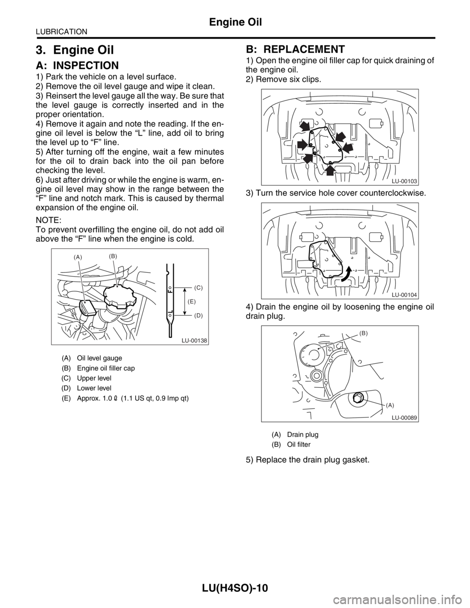
A: INSPECTION
1) Park the vehicle on a level surface.
2) Remove the oil level gauge and wipe it clean.
3) Reinsert the level gauge all the way. Be sure that
the level gauge is correctly inserted and in the
proper orientation.
4) Remove it again and note the reading. If the en-
gine oil level is below the “L” line, add oil to bring
the level up to “F” line.
5) After turning off the engine, wait a few minutes
for the oil to drain back into the oil pan before
checking the level.
6) Just after driving or while the engine is warm, en-
gine oil level may show in the range between the
“F” line and notch mark. This is caused by thermal
expansion of the engine oil.
NOTE:
To prevent overfilling the engine oil, do not add oil
above the “F” line when the engine is cold.
B: REPLACEMENT
1) Open the engine oil filler cap for quick draining of
the engine oil.
2) Remove six clips.
3) Turn the service hole cover counterclockwise.
4) Drain the engine oil by loosening the engine oil
drain plug.
5) Replace the drain plug gasket.
(A) Oil level gauge
(B) Engine oil filler cap
(C) Upper level
(D) Lower level
(E) Approx. 1.02 (1.1 US qt, 0.9 Imp qt)
LU-00138
(A)(B)
(C)
(D) (E)
(A) Drain plug
(B) Oil filter
LU-00103
LU-00104
LU-00089
(B)
(A)
Page 1051 of 2870
LU(H4SO)-23
LUBRICATION
Engine Oil Filter
8. Engine Oil Filter
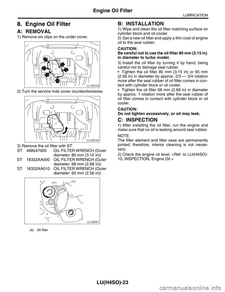
A: REMOVAL
1) Remove six clips on the under cover.
2) Turn the service hole cover counterclockwise.
3) Remove the oil filter with ST.
ST 498547000 OIL FILTER WRENCH (Outer
diameter: 80 mm (3.15 in))
ST 18332AA000 OIL FILTER WRENCH (Outer
diameter: 68 mm (2.68 in))
ST 18332AA010 OIL FILTER WRENCH (Outer
diameter: 65 mm (2.56 in))
B: INSTALLATION
1) Wipe and clean the oil filter matching surface on
cylinder block and oil cooler.
2) Get a new oil filter and apply a thin coat of engine
oil to the seal rubber.
CAUTION:
Be careful not to use the oil filter 80 mm (3.15 in)
in diameter to turbo model.
3) Install the oil filter by turning it by hand, being
careful not to damage seal rubber.
Tighten the oil filter 80 mm (3.15 in) or 65 mm
(2.56 in) in diameter by approx. 2/3 — 3/4 rotation
more after the seal rubber of oil filter comes in con-
tact with cylinder block or oil cooler.
Tighten the oil filter 68 mm (2.68 in) in diameter
by approx. 1 rotation more after the seal rubber of
oil filter comes in contact with cylinder block or oil
cooler.
CAUTION:
Do not tighten excessively, or oil may leak.
C: INSPECTION
1) After installing the oil filter, run the engine and
make sure that no oil is leaking around seal rubber.
NOTE:
The filter element and filter case are permanently
jointed; therefore, interior cleaning is not neces-
sary.
2) Check the engine oil level.
(A) Oil filter
LU-00103
LU-00104
LU-00091
(A)
Page 1077 of 2870

SC(H4SO)-2
STARTING/CHARGING SYSTEM
General Description
1. General Description
A: SPECIFICATION
Item Designation
StarterType Reduction type
Vehicle type MT model AT model
Model M000T30471 M000T20171
Manufacturer Mitsubishi Electric
Voltage and output 12 V — 1.0 kW 12 V — 1.4 kW
Direction of rotation Counterclockwise (viewed from pinion gear side)
Number of pinion teeth 8 9
No-load charac-
teristicsVo l t a g e 1 1 V
Current 95 A or less 90 A or less
Rotating speed 2,500 rpm or more 2,000 rpm or more
Load character-
isticsVoltage 7.5 V 7.7 V
Current 300 A 400 A
Torque 8.84 N (0.90 kgf, 1.99 lb) or more 16.7 N (1.70 kgf, 3.75 lb) or more
Rotating speed 870 rpm or more 710 rpm or more
Lock character-
isticsVo l t a g e 4 V 3 . 5 V
Current 680 A or less 960 A or less
Torque 17 N (1.73 kgf, 12.5 lb) or more 31 N (3.16 kgf, 22.9 lb) or more
GeneratorTy p eRotating-field three-phase type, Voltage regulator built-in type, with load
response control system
ModelEC, EK model: A002TG0391
Other model: A002TB6991
Manufacturer Mitsubishi Electric
Voltage and output 12 V — 90 A
Polarity on ground side Negative
Rotating direction Clockwise (viewed from pulley side)
Armature connection 3-phase Y-type
Output currentEC, EK model1,500 rpm — 40 A or more
2,500 rpm — 74 A or more
5,000 rpm — 84 A or more
Other model1,500 rpm — 36 A or more
2,500 rpm — 65 A or more
5,000 rpm — 86 A or more
Regulated voltage 14.1 — 14.8 V [20°C (68°F)]