2004 SUBARU FORESTER charging
[x] Cancel search: chargingPage 3 of 2870

HVAC SYSTEM
(HEATER, VENTILATOR AND A/C)
AC
Page
1. General Description ....................................................................................2
2. Refrigerant Pressure with Manifold Gauge Set .........................................25
3. Refrigerant Recovery Procedure...............................................................26
4. Refrigerant Charging Procedure ...............................................................27
5. Refrigerant Leak Check ............................................................................30
6. Compressor Oil .........................................................................................31
7. Blower Motor Unit Assembly .....................................................................32
8. Blower Resistor (Manual A/C Model) ........................................................33
9. Heater Core...............................................................................................34
10. Control Unit ...............................................................................................35
11. Compressor...............................................................................................36
12. Condenser.................................................................................................37
13. Condenser (Sub Fan)................................................................................38
14. Heater Cooling Unit ...................................................................................39
15. Evaporator.................................................................................................40
16. Hose and Tube..........................................................................................41
17. Relay and Fuse .........................................................................................42
18. Pressure Switch (Triple Pressure Switch) .................................................43
19. Ambient Sensor (Auto A/C Model) ............................................................44
20. Sunload Sensor (Auto A/C Model) ............................................................45
21. Air Vent Grille ............................................................................................46
22. Heater Duct ...............................................................................................47
23. Heater Vent Duct.......................................................................................48
24. Heater Cock Solenoid Valve .....................................................................49
25. General Diagnostics ..................................................................................50
Page 26 of 2870
AC-24
HVAC SYSTEM (HEATER, VENTILATOR AND A/C)
General Description
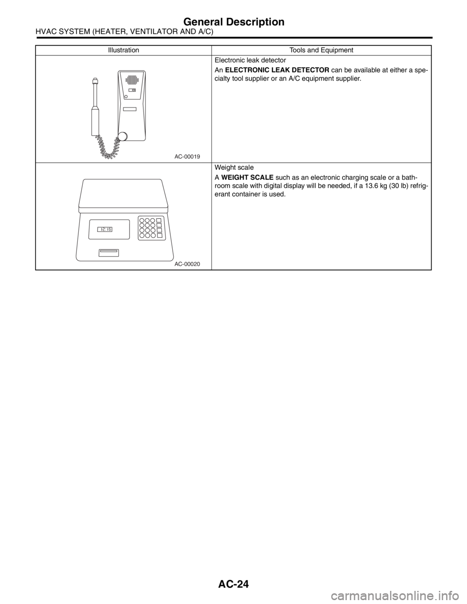
Electronic leak detector
An ELECTRONIC LEAK DETECTOR can be available at either a spe-
cialty tool supplier or an A/C equipment supplier.
Weight scale
A WEIGHT SCALE such as an electronic charging scale or a bath-
room scale with digital display will be needed, if a 13.6 kg (30 lb) refrig-
erant container is used. Illustration Tools and Equipment
AC-00019
AC-00020
Page 29 of 2870
AC-27
HVAC SYSTEM (HEATER, VENTILATOR AND A/C)
Refrigerant Charging Procedure
4. Refrigerant Charging Proce-
dure
A: OPERATION
CAUTION:
During operation, be sure to wear safety gog-
gles and protective gloves.
If air is mixed in refrigeration cycle, poor cool-
ing may result, and also if moisture is mixed in re-
frigeration cycle, clogging (freezing) or rust may
result.
Before charging the refrigerant, evacuate the
system using vacuum pump to remove air and
moisture in the system. Moisture can be evapo-
rated and removed easily even at normal tem-
perature, if the system is evacuated using
vacuum pump.
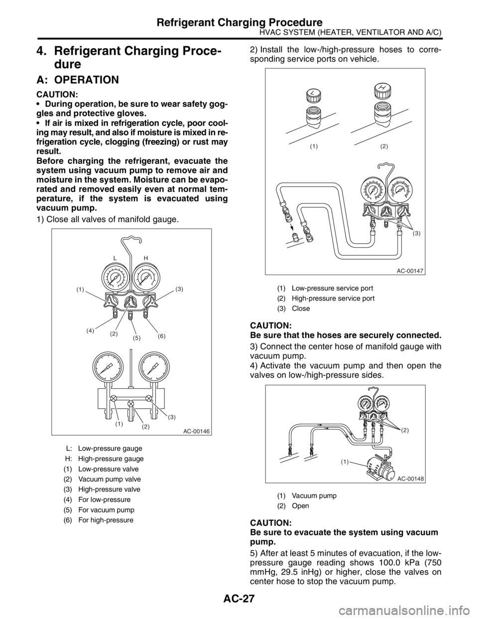
1) Close all valves of manifold gauge.2) Install the low-/high-pressure hoses to corre-
sponding service ports on vehicle.
CAUTION:
Be sure that the hoses are securely connected.
3) Connect the center hose of manifold gauge with
vacuum pump.
4) Activate the vacuum pump and then open the
valves on low-/high-pressure sides.
CAUTION:
Be sure to evacuate the system using vacuum
pump.
5) After at least 5 minutes of evacuation, if the low-
pressure gauge reading shows 100.0 kPa (750
mmHg, 29.5 inHg) or higher, close the valves on
center hose to stop the vacuum pump.
L: Low-pressure gauge
H: High-pressure gauge
(1) Low-pressure valve
(2) Vacuum pump valve
(3) High-pressure valve
(4) For low-pressure
(5) For vacuum pump
(6) For high-pressure
AC-00146
(2) (4)
(5)(6)
(3)(3)
(2) (1)H L
(1)
(1) Low-pressure service port
(2) High-pressure service port
(3) Close
(1) Vacuum pump
(2) Open
AC-00147
(3) (2) (1)
AC-00148
(1)(2)
Page 30 of 2870
AC-28
HVAC SYSTEM (HEATER, VENTILATOR AND A/C)
Refrigerant Charging Procedure
6) Leave it at least 5 to 10 minutes after closing the
valves on low-/high-pressure sides, and then check
the low-pressure gauge reading for any changes.
When the gauge reading changes, this is a sign of
leakage. Check the pipe or hose connector points,
and repair if necessary. Repeat the procedure from
1) after repairing the faulty part.
7) If there are no leaks, further evacuate the sys-
tem 20 to 30 minutes.
8) Close all valves and stop the vacuum pump.
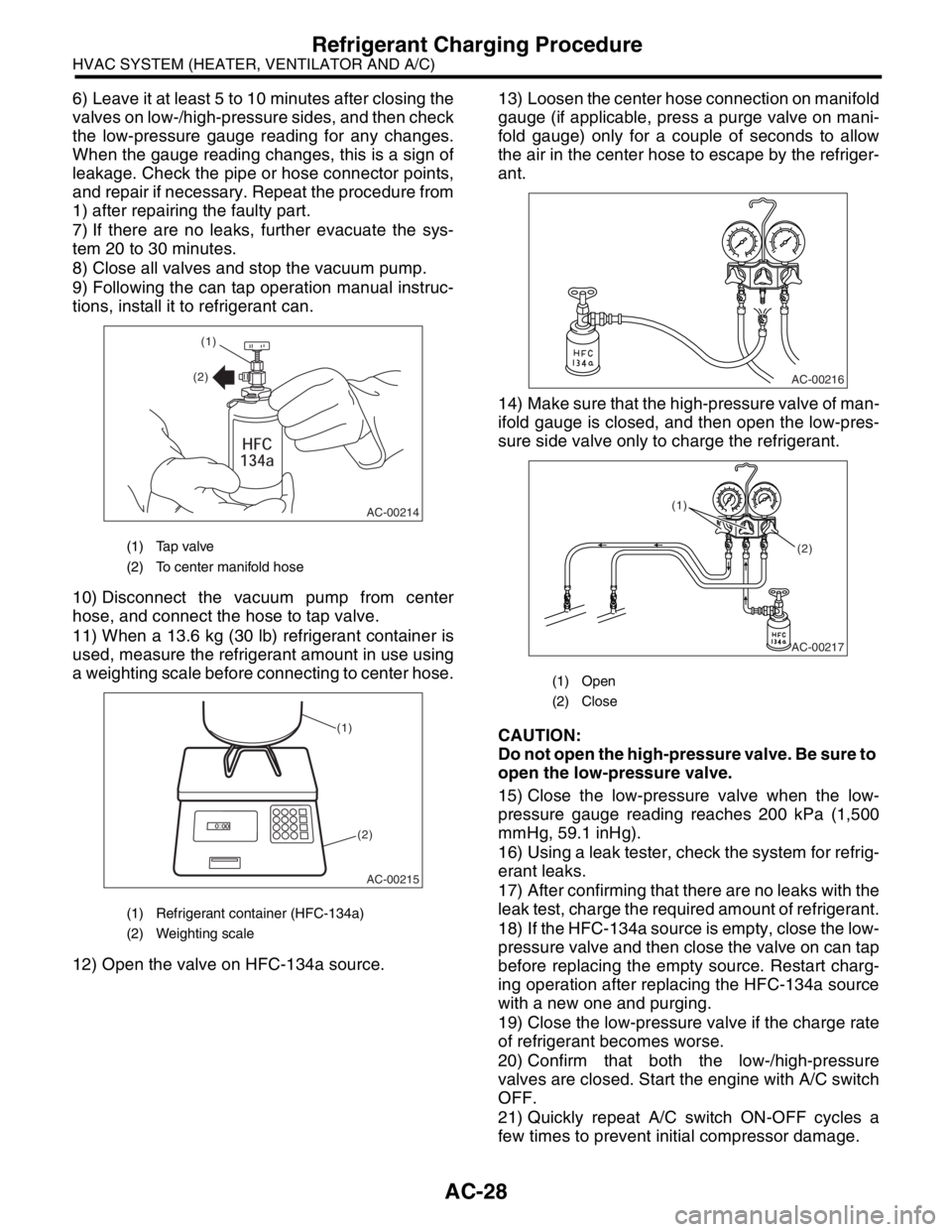
9) Following the can tap operation manual instruc-
tions, install it to refrigerant can.
10) Disconnect the vacuum pump from center
hose, and connect the hose to tap valve.
11) When a 13.6 kg (30 lb) refrigerant container is
used, measure the refrigerant amount in use using
a weighting scale before connecting to center hose.
12) Open the valve on HFC-134a source.13) Loosen the center hose connection on manifold
gauge (if applicable, press a purge valve on mani-
fold gauge) only for a couple of seconds to allow
the air in the center hose to escape by the refriger-
ant.
14) Make sure that the high-pressure valve of man-
ifold gauge is closed, and then open the low-pres-
sure side valve only to charge the refrigerant.
CAUTION:
Do not open the high-pressure valve. Be sure to
open the low-pressure valve.
15) Close the low-pressure valve when the low-
pressure gauge reading reaches 200 kPa (1,500
mmHg, 59.1 inHg).
16) Using a leak tester, check the system for refrig-
erant leaks.
17) After confirming that there are no leaks with the
leak test, charge the required amount of refrigerant.
18) If the HFC-134a source is empty, close the low-
pressure valve and then close the valve on can tap
before replacing the empty source. Restart charg-
ing operation after replacing the HFC-134a source
with a new one and purging.
19) Close the low-pressure valve if the charge rate
of refrigerant becomes worse.
20) Confirm that both the low-/high-pressure
valves are closed. Start the engine with A/C switch
OFF.
21) Quickly repeat A/C switch ON-OFF cycles a
few times to prevent initial compressor damage.
(1) Tap valve
(2) To center manifold hose
(1) Refrigerant container (HFC-134a)
(2) Weighting scale
AC-00214
(1)
(2)
AC-00215
(1)
(2)
(1) Open
(2) Close
AC-00216
AC-00217
(1)
(2)
Page 31 of 2870

AC-29
HVAC SYSTEM (HEATER, VENTILATOR AND A/C)
Refrigerant Charging Procedure
22) Set up the vehicle to the following status:
A/C switch ON
Engine running at 1,500 rpm
Blower speed setting to “HI”
Temperature setting to “MAX COOL”
Air inlet setting to “RECIRC”
Window open
23) Open the low-pressure valve and charge the
specified amount of refrigerant.
24) Close all valves and disconnect the hoses from
service port after charging the refrigerant.
25) Install the cap to service port.
Page 38 of 2870
AC-36
HVAC SYSTEM (HEATER, VENTILATOR AND A/C)
Compressor
11.Compressor
A: INSPECTION
1. MAGNETIC CLUTCH CLEARANCE
1) Check the clearance of the entire circumference
around the drive plate and pulley.
Standard:
0.3 — 0.6 mm (0.0118 — 0.0236 in)
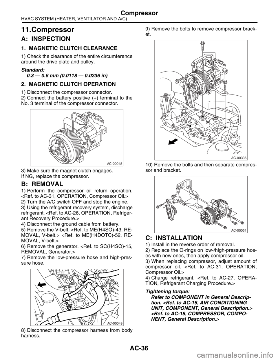
2. MAGNETIC CLUTCH OPERATION
1) Disconnect the compressor connector.
2) Connect the battery positive (+) terminal to the
No. 3 terminal of the compressor connector.
3) Make sure the magnet clutch engages.
If NG, replace the compressor.
B: REMOVAL
1) Perform the compressor oil return operation.
2) Turn the A/C switch OFF and stop the engine.
3) Using the refrigerant recovery system, discharge
refrigerant.
4) Disconnect the ground cable from battery.
5) Remove the V-belt.
6) Remove the generator.
7) Remove the low-pressure hose and high-pres-
sure hose.
8) Disconnect the compressor harness from body
harness.9) Remove the bolts to remove compressor brack-
et.
10) Remove the bolts and then separate compres-
sor and bracket.
C: INSTALLATION
1) Install in the reverse order of removal.
2) Replace the O-rings on low-/high-pressure hos-
es with new ones, then apply compressor oil.
3) When replacing compressor, adjust amount of
compressor oil.
4) Charge refrigerant.
Tightening torque:
Refer to COMPONENT in General Descrip-
tion.
AC-00048
AC-00049
AC-00336
AC-00051
Page 39 of 2870
AC-37
HVAC SYSTEM (HEATER, VENTILATOR AND A/C)
Condenser
12.Condenser
A: REMOVAL
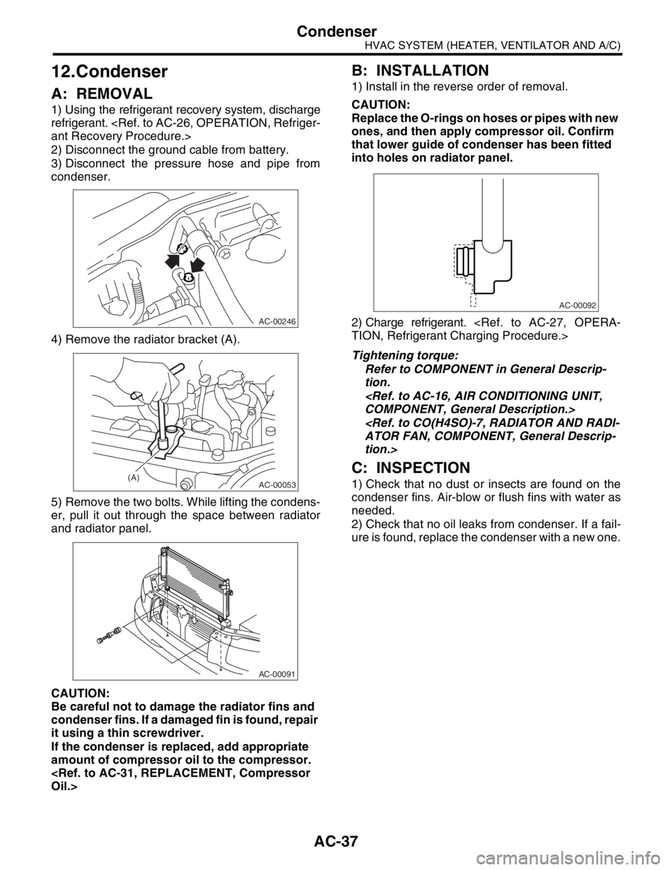
1) Using the refrigerant recovery system, discharge
refrigerant.
2) Disconnect the ground cable from battery.
3) Disconnect the pressure hose and pipe from
condenser.
4) Remove the radiator bracket (A).
5) Remove the two bolts. While lifting the condens-
er, pull it out through the space between radiator
and radiator panel.
CAUTION:
Be careful not to damage the radiator fins and
condenser fins. If a damaged fin is found, repair
it using a thin screwdriver.
If the condenser is replaced, add appropriate
amount of compressor oil to the compressor.
B: INSTALLATION
1) Install in the reverse order of removal.
CAUTION:
Replace the O-rings on hoses or pipes with new
ones, and then apply compressor oil. Confirm
that lower guide of condenser has been fitted
into holes on radiator panel.
2) Charge refrigerant.
Tightening torque:
Refer to COMPONENT in General Descrip-
tion.
tion.>
C: INSPECTION
1) Check that no dust or insects are found on the
condenser fins. Air-blow or flush fins with water as
needed.
2) Check that no oil leaks from condenser. If a fail-
ure is found, replace the condenser with a new one.
AC-00246
AC-00053(A)
AC-00091
AC-00092
Page 41 of 2870
AC-39
HVAC SYSTEM (HEATER, VENTILATOR AND A/C)
Heater Cooling Unit
14.Heater Cooling Unit
A: REMOVAL
1) Disconnect the ground cable from battery.
2) Using the refrigerant recovery system, dis-
charge refrigerant.
3) Drain the engine coolant from radiator.
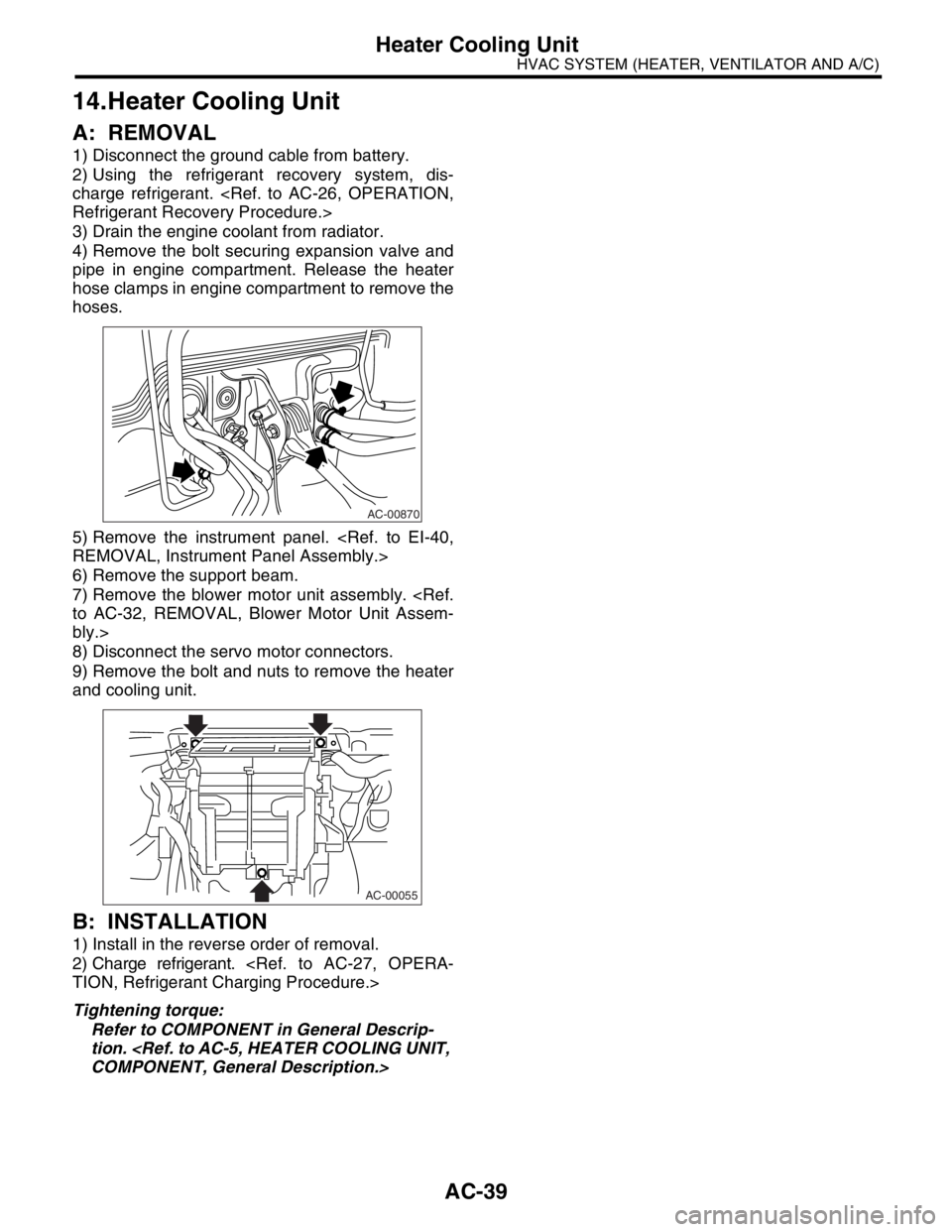
4) Remove the bolt securing expansion valve and
pipe in engine compartment. Release the heater
hose clamps in engine compartment to remove the
hoses.
5) Remove the instrument panel.
6) Remove the support beam.
7) Remove the blower motor unit assembly.
bly.>
8) Disconnect the servo motor connectors.
9) Remove the bolt and nuts to remove the heater
and cooling unit.
B: INSTALLATION
1) Install in the reverse order of removal.
2) Charge refrigerant.
Tightening torque:
Refer to COMPONENT in General Descrip-
tion.
AC-00870
AC-00055