2004 SUBARU FORESTER glove box
[x] Cancel search: glove boxPage 34 of 2870
AC-32
HVAC SYSTEM (HEATER, VENTILATOR AND A/C)
Blower Motor Unit Assembly
7. Blower Motor Unit Assembly
A: REMOVAL
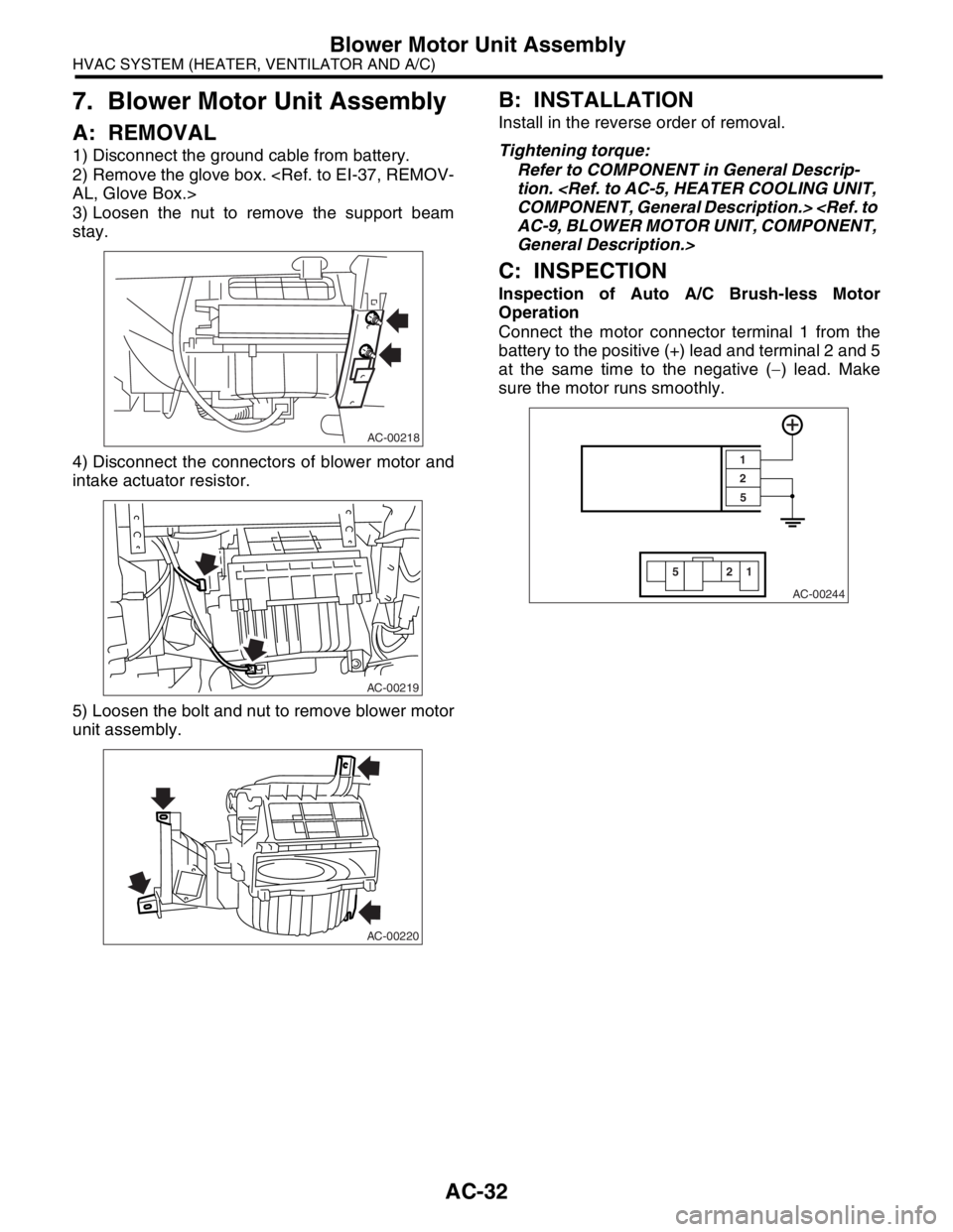
1) Disconnect the ground cable from battery.
2) Remove the glove box.
3) Loosen the nut to remove the support beam
stay.
4) Disconnect the connectors of blower motor and
intake actuator resistor.
5) Loosen the bolt and nut to remove blower motor
unit assembly.
B: INSTALLATION
Install in the reverse order of removal.
Tightening torque:
Refer to COMPONENT in General Descrip-
tion.
General Description.>
C: INSPECTION
Inspection of Auto A/C Brush-less Motor
Operation
Connect the motor connector terminal 1 from the
battery to the positive (+) lead and terminal 2 and 5
at the same time to the negative (−) lead. Make
sure the motor runs smoothly.
AC-00218
AC-00219
AC-00220
AC-00244
22
55
1 1
Page 35 of 2870
AC-33
HVAC SYSTEM (HEATER, VENTILATOR AND A/C)
Blower Resistor (Manual A/C Model)
8. Blower Resistor (Manual A/C
Model)
A: REMOVAL
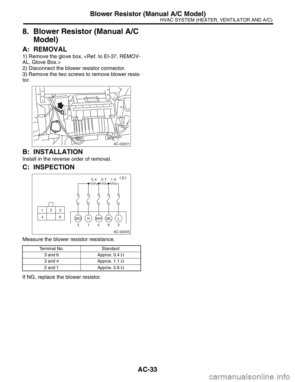
1) Remove the glove box.
2) Disconnect the blower resistor connector.
3) Remove the two screws to remove blower resis-
tor.
B: INSTALLATION
Install in the reverse order of removal.
C: INSPECTION
Measure the blower resistor resistance.
If NG, replace the blower resistor.
Terminal No. Standard
3 and 6 Approx. 0.4 Ω
3 and 4 Approx. 1.1 Ω
2 and 1 Approx. 2.6 Ω
AC-00221
AC-00245
MOHMHMLL
23 6
4 1
0.4 0.7 1.5
12 3
46
Page 42 of 2870
AC-40
HVAC SYSTEM (HEATER, VENTILATOR AND A/C)
Evaporator
15.Evaporator
A: REMOVAL
1) Perform the refrigerant recovery operation, and
then disconnect the toe board area A/C pipe.
cedure.>
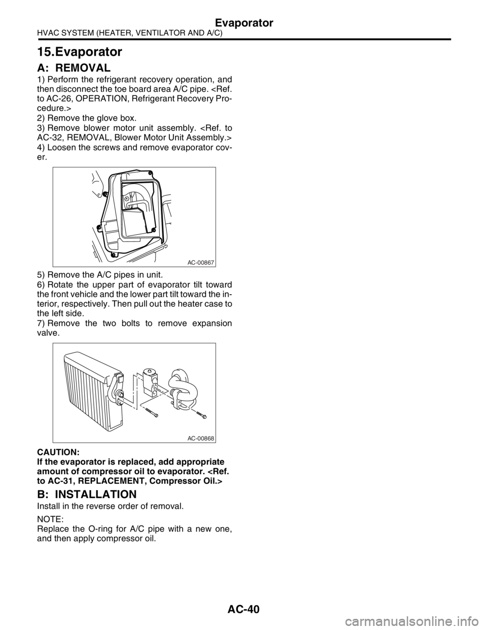
2) Remove the glove box.
3) Remove blower motor unit assembly.
4) Loosen the screws and remove evaporator cov-
er.
5) Remove the A/C pipes in unit.
6) Rotate the upper part of evaporator tilt toward
the front vehicle and the lower part tilt toward the in-
terior, respectively. Then pull out the heater case to
the left side.
7) Remove the two bolts to remove expansion
valve.
CAUTION:
If the evaporator is replaced, add appropriate
amount of compressor oil to evaporator.
B: INSTALLATION
Install in the reverse order of removal.
NOTE:
Replace the O-ring for A/C pipe with a new one,
and then apply compressor oil.
AC-00867
AC-00868
Page 94 of 2870

AC-38
HVAC SYSTEM (AUTO A/C)(DIAGNOSTIC)
Diagnostic Procedure for Sensors
Step Check Yes No
1 CHECK EVAPORATOR SENSOR.
1) Turn the ignition switch to OFF.
2) Remove the glove box.
3) Disconnect the connector from evaporator
sensor.
4) Measure the resistance between connector
terminals of evaporator sensor.
Te r m i n a l s
No. 1 — No. 2:Is the resistance approx. 2.7
kΩ at 20°C (68°F)?Go to step 2.Replace the evap-
orator sensor.
2 CHECK INPUT SIGNAL FOR EVAPORATOR
SENSOR.
1) Turn the ignition switch to ON.
2) Measure the voltage between connector
(B256) terminal and chassis ground.
Connector & terminal
(B256) No. 1 (+) — Chassis ground (
−):Is the voltage approx. 5 V? Go to step 5.Go to step 3.
3 CHECK AUTO A/C CONTROL MODULE
OUTPUT SIGNAL.
1) Turn the ignition switch to OFF.
2) Remove the auto A/C control module.
3) Turn the ignition switch to ON.
4) Measure the voltage between connector
terminals of auto A/C control module.
Connector & terminal
(i49) No. 2 (+) — (i48) No. 16 (
−):Is the voltage approx. 5 V? Go to step 4.Go to step 6.
4 CHECK HARNESS CONNECTOR BETWEEN
AUTO A/C CONTROL MODULE AND EVAP-
ORATOR SENSOR.
1) Turn the ignition switch to OFF.
2) Disconnect the connector from auto A/C
control module.
3) Measure the resistance in harness
between auto A/C control module and evapo-
rator sensor.
Connector & terminal
(B256) No. 1 — (i49) No. 2:Is the resistance less than 1Ω? Go to step 5.Repair the open
circuit in harness
between auto A/C
control module
and evaporator
sensor.
5 CHECK HARNESS CONNECTOR BETWEEN
AUTO A/C CONTROL MODULE AND EVAP-
ORATOR SENSOR.
Measure the resistance in harness between
auto A/C control module and evaporator sen-
sor.
Connector & terminal
(B256) No. 3 — (i48) No. 16:Is the resistance less than 1
Ω?Go to step 6.Repair the open
circuit in harness
between auto A/C
control module
and evaporator
sensor.
6 CHECK POOR CONTACT.
Check poor contact in auto A/C control module
connector.Is there poor contact in con-
nector?Repair the con-
nector.Replace the auto
A/C control mod-
ule.
Page 115 of 2870
AB-15
AIRBAG SYSTEM
Passenger’s Airbag Module
5. Passenger’s Airbag Module
A: REMOVAL
CAUTION:
Refer to “CAUTION” in General Description be-
fore handing the airbag module.
1) Turn the ignition switch to OFF.
2) Disconnect the ground cable from battery, and
wait for at least 20 seconds before starting work.
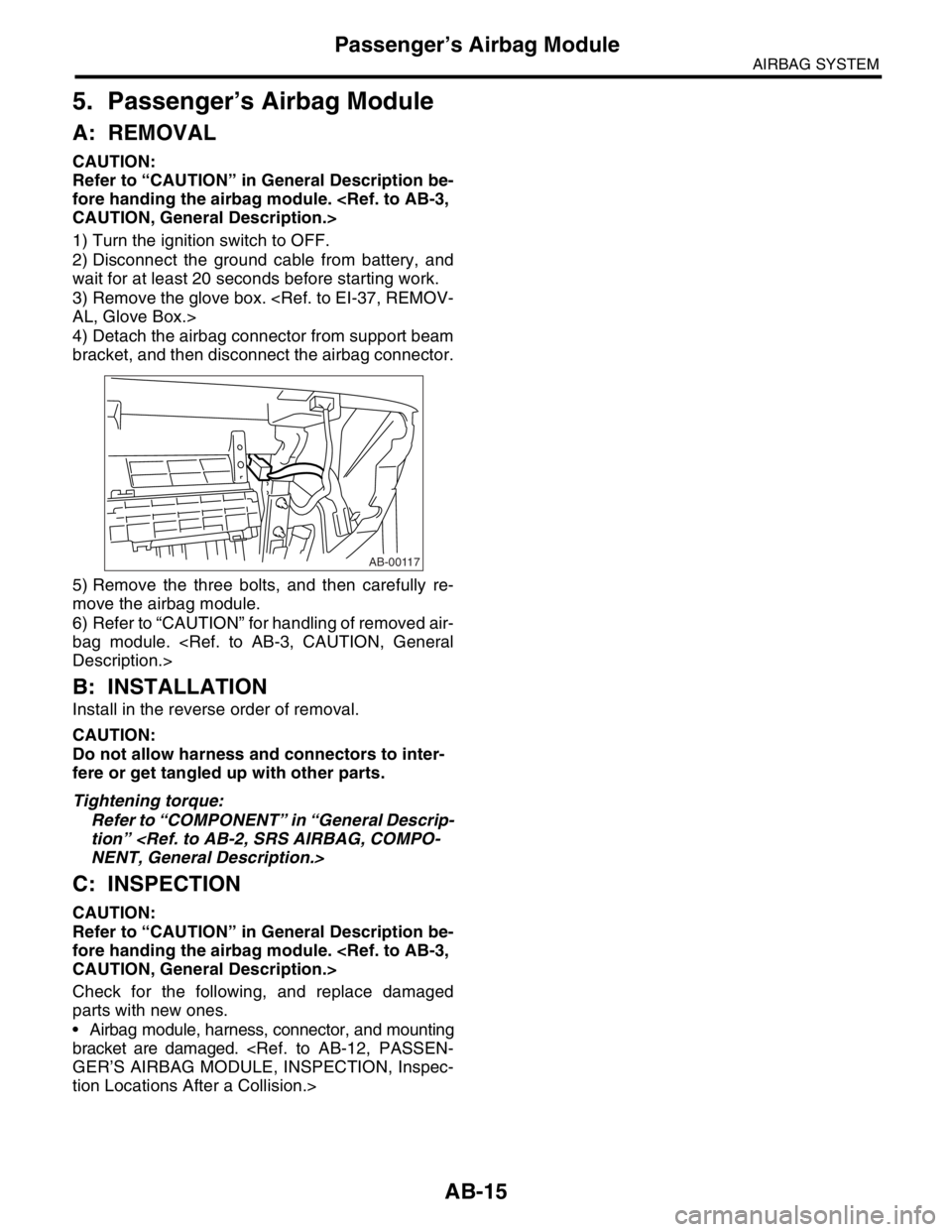
3) Remove the glove box.
4) Detach the airbag connector from support beam
bracket, and then disconnect the airbag connector.
5) Remove the three bolts, and then carefully re-
move the airbag module.
6) Refer to “CAUTION” for handling of removed air-
bag module.
B: INSTALLATION
Install in the reverse order of removal.
CAUTION:
Do not allow harness and connectors to inter-
fere or get tangled up with other parts.
Tightening torque:
Refer to “COMPONENT” in “General Descrip-
tion”
C: INSPECTION
CAUTION:
Refer to “CAUTION” in General Description be-
fore handing the airbag module.
Check for the following, and replace damaged
parts with new ones.
Airbag module, harness, connector, and mounting
bracket are damaged.
tion Locations After a Collision.>
AB-00117
Page 123 of 2870
AB-23
AIRBAG SYSTEM
Airbag Module Disposal (Deployment Processing On Vehicle)
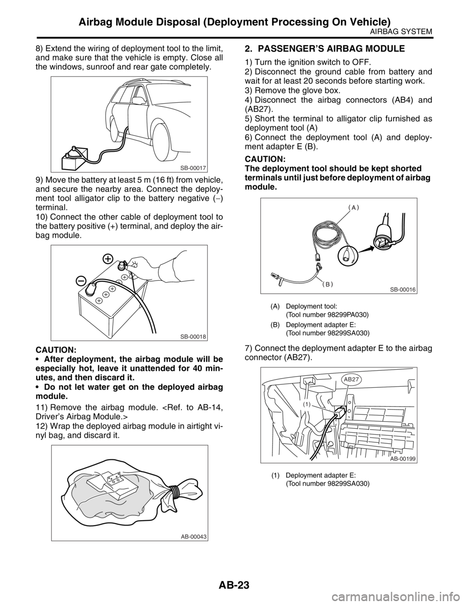
8) Extend the wiring of deployment tool to the limit,
and make sure that the vehicle is empty. Close all
the windows, sunroof and rear gate completely.
9) Move the battery at least 5 m (16 ft) from vehicle,
and secure the nearby area. Connect the deploy-
ment tool alligator clip to the battery negative (−)
terminal.
10) Connect the other cable of deployment tool to
the battery positive (+) terminal, and deploy the air-
bag module.
CAUTION:
After deployment, the airbag module will be
especially hot, leave it unattended for 40 min-
utes, and then discard it.
Do not let water get on the deployed airbag
module.
11) Remove the airbag module.
12) Wrap the deployed airbag module in airtight vi-
nyl bag, and discard it.2. PASSENGER’S AIRBAG MODULE
1) Turn the ignition switch to OFF.
2) Disconnect the ground cable from battery and
wait for at least 20 seconds before starting work.
3) Remove the glove box.
4) Disconnect the airbag connectors (AB4) and
(AB27).
5) Short the terminal to alligator clip furnished as
deployment tool (A)
6) Connect the deployment tool (A) and deploy-
ment adapter E (B).
CAUTION:
The deployment tool should be kept shorted
terminals until just before deployment of airbag
module.
7) Connect the deployment adapter E to the airbag
connector (AB27).
SB-00017
SB-00018
AB-00043
(A) Deployment tool:
(Tool number 98299PA030)
(B) Deployment adapter E:
(Tool number 98299SA030)
(1) Deployment adapter E:
(Tool number 98299SA030)
SB-00016
AB-00199
AB27
(1)
Page 168 of 2870

AB-36
AIRBAG SYSTEM (DIAGNOSTIC)
Airbag Warning Light Failure
2 CHECK AIRBAG WARNING LIGHT.
1) Turn the ignition switch to OFF, disconnect
the battery ground cable, and wait more than
20 seconds.
2) Connect the connector (1T) in test harness
T to body harness connector (B31).
3) Connect the connector (1M) in test harness
M to connector (2T) in test harness T.
4) Connect the battery ground cable and turn
the ignition switch to ON.
5) Connect the connectors, (3M) and (4M) in
test harness M.Is the airbag warning light
turned off?Go to step 4.Go to step 3.
3 CHECK BODY HARNESS.
Check the body harness.
N
OTE:
After problem has been eliminated, disconnect
the connectors (3M) and (4M).Is the anything unusual to body
harness? Repair the body
harness.Replace the com-
bination meter
printed circuit.
Meter Assembly.>
4 CHECK POOR CONTACT.
Confirm that firm contact is secured between
the airbag control module and the connector
(AB3).
tor (AB3)?Replace the airbag
main harness with
body harness or
replace the airbag
control module.
Module.>Go to step 5.
5 CHECK AIRBAG MAIN HARNESS.
1) Turn the ignition switch to OFF, disconnect
the battery ground cable, and wait more than
20 seconds.
2) Connect the connector (AB1) to (B31).
3) Disconnect the connectors (AB2) and
(AB30).
4) Remove the glove box and disconnect the
connectors (AB4).
5) Disconnect the connector (AB3) from the
airbag control module, and connect the con-
nector (1R) in test harness R.
6) Connect the battery ground cable and turn
the ignition switch to ON.
7) Connect the connectors (5R) and (6R) in
test harness R.
N
OTE:
After problem has been eliminated, disconnect
the connectors (5R) and (6R).Is the airbag warning light
turned off?Go to step 6.Replace the airbag
main harness with
body harness.
6 CHECK GROUNDING CIRCUIT.
1) Turn the ignition switch to OFF, disconnect
the battery ground cable, and wait more than
20 seconds.
2) Disconnect the connector (AB3) from the
airbag control module.
3) Connect the connector (1R) in test harness
R to body harness connector (AB3).
4) Measure the resistance between connector
(2R) in test harness R and the chassis ground.
Connector & terminal
(2R) No. 10 — Chassis ground:
(2R) No. 11 — Chassis ground: Is the resistance less than 10
Ω?Replace the airbag
control module.
Module.>Repair the body-
grounding circuit. Step Check Yes No
Page 170 of 2870

AB-38
AIRBAG SYSTEM (DIAGNOSTIC)
Airbag Warning Light Failure
2 CHECK AIRBAG WARNING LIGHT.
1) Turn the ignition switch to OFF, disconnect
the battery ground cable, and wait more than
20 seconds.
2) Connect the connector (1M) in test harness
M to body harness connector (B31).
3) Connect the battery ground cable and turn
the ignition switch to ON.
4) Connect the connectors, (3M) and (4M) in
test harness M.Is the airbag warning light
turned off?Go to step 4.Go to step 3.
3 CHECK BODY HARNESS.
Check the body harness.
N
OTE:
After problem has been eliminated, disconnect
the connectors (3M) and (4M).Is the anything unusual to body
harness?Repair the body
harness.Replace the com-
bination meter
printed circuit.
Meter Assembly.>
4 CHECK POOR CONTACT.
Confirm that firm contact is secured between
the airbag control module and the connector
(AB3).
tor (AB3)? Replace the airbag
main harness with
body harness or
replace the airbag
control module.
Module.>Go to step 5.
5 CHECK AIRBAG MAIN HARNESS.
1) Turn the ignition switch to OFF, disconnect
the battery ground cable, and wait more than
20 seconds.
2) Connect the connector (AB1) to (B31).
3) Disconnect the connectors (AB21) and
(AB26).
4) Remove the glove box and disconnect the
connectors (AB4).
5) Disconnect the connector (AB3) from the
airbag control module, and connect the con-
nector (1R) in test harness R.
6) Connect the battery ground cable and turn
the ignition switch to ON.
7) Connect the connectors (5R) and (6R) in
test harness R.
N
OTE:
After problem has been eliminated, disconnect
the connectors (5R) and (6R).Is the airbag warning light
turned off? Go to step 6.Replace the airbag
main harness with
body harness.
6 CHECK GROUNDING CIRCUIT.
1) Turn the ignition switch to OFF, disconnect
the battery ground cable, and wait more than
20 seconds.
2) Disconnect the connector (AB3) from the
airbag control module.
3) Connect the connector (1R) in test harness
R to body harness connector (AB3).
4) Measure the resistance between connector
(2R) in test harness R and the chassis ground.
Connector & terminal
(2R) No. 10 — Chassis ground:
(2R) No. 11 — Chassis ground: Is the resistance less than 10
Ω?Replace the airbag
control module.
Module.>Repair the body-
grounding circuit. Step Check Yes No