Page 1078 of 2870
SC(H4SO)-3
STARTING/CHARGING SYSTEM
General Description
B: COMPONENT
1. STARTER
(1) Front bracket (7) Internal gear ASSY (13) Brush holder ASSY
(2) Sleeve bearing (8) Shaft ASSY (14) Sleeve bearing
(3) Lever set (9) Gear ASSY (15) Rear cover
(4) Magnet switch ASSY (10) Packing (16) Rear cover set
(5) Stopper set (11) Yoke ASSY
(6) Over running clutch (12) Armature
SC-00058
(14) (1)
(2)(3)(4)
(10)
(11)(12)
(13)(15)(16) (5)(6)(7)(8) (9)
Page 1079 of 2870
SC(H4SO)-4
STARTING/CHARGING SYSTEM
General Description
2. GENERATOR
(1) Pulley (5) Rotor (9) Brush
(2) Front cover (6) Bearing (10) Rectifier
(3) Ball bearing (7) Stator coil (11) Rear cover
(4) Bearing retainer (8) IC regulator with brush (12) Terminal
SC-00144
(1)
(2)
(7)
(8)
(9)
(10)
(11)
(12)
(3)
(4)
(5)(6)
Page 1080 of 2870
SC(H4SO)-5
STARTING/CHARGING SYSTEM
General Description
C: CAUTION
Wear working clothing, including a cap, protec-
tive goggles, and protective shoes during opera-
tion.
Remove contamination including dirt and corro-
sion before removal, installation or disassembly.
Keep the disassembled parts in order and pro-
tect them from dust or dirt.
Before removal, installation or disassembly, be
sure to clarify the failure. Avoid unnecessary re-
moval, installation, disassembly, and replacement.
Be careful not to burn yourself, because each
part in the vehicle is hot after running.
Be sure to tighten fasteners including bolts and
nuts to the specified torque.
Place shop jacks or rigid racks at the specified
points.
Before disconnecting electrical connectors of
sensors or units, be sure to disconnect the ground
cable from battery.
Page 1081 of 2870
SC(H4SO)-6
STARTING/CHARGING SYSTEM
Starter
2. Starter
A: REMOVAL
1) Disconnect the ground cable from battery.
2) Remove the air cleaner case. (Non-turbo model)
Case.>
3) Remove the intercooler. (Turbo model)
IN(H4DOTC)-10, REMOVAL, Intercooler.>
4) Remove the air cleaner case stay. (Non-turbo
model)
MT model
AT model5) Disconnect the connector and terminal from
starter.
6) Remove the starter from transmission.
B: INSTALLATION
Install in the reverse order of removal.
Tightening torque:
50 N
⋅m (5.1 kgf-m, 37 ft-lb)
FU-00009
SC-00004
SC-00005
(A) Terminal
(B) Connector
SC-00006
SC-00007
SC-00007
Page 1082 of 2870

SC(H4SO)-7
STARTING/CHARGING SYSTEM
Starter
C: DISASSEMBLY
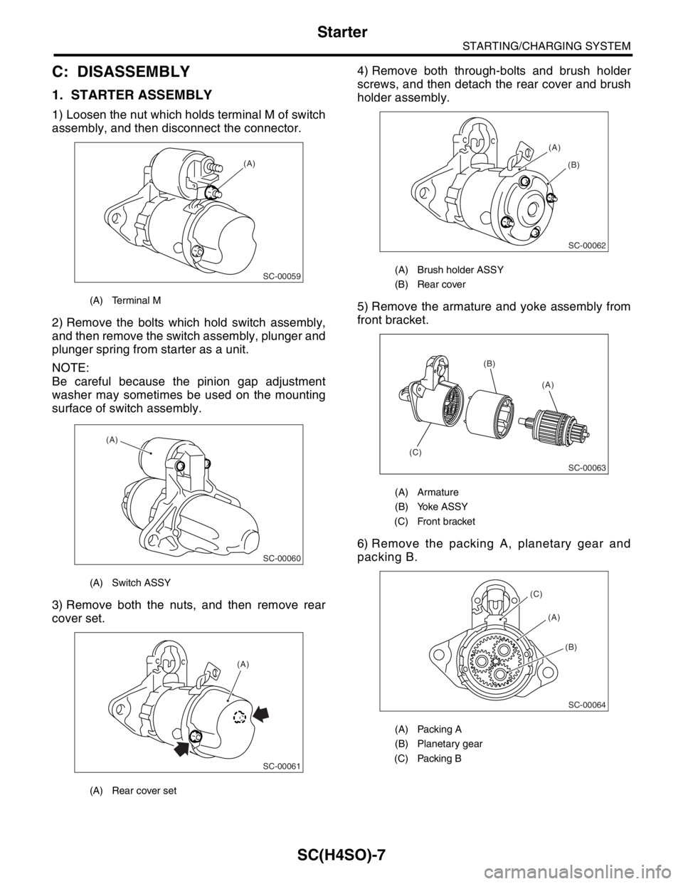
1. STARTER ASSEMBLY
1) Loosen the nut which holds terminal M of switch
assembly, and then disconnect the connector.
2) Remove the bolts which hold switch assembly,
and then remove the switch assembly, plunger and
plunger spring from starter as a unit.
NOTE:
Be careful because the pinion gap adjustment
washer may sometimes be used on the mounting
surface of switch assembly.
3) Remove both the nuts, and then remove rear
cover set.4) Remove both through-bolts and brush holder
screws, and then detach the rear cover and brush
holder assembly.
5) Remove the armature and yoke assembly from
front bracket.
6) Remove the packing A, planetary gear and
packing B.
(A) Terminal M
(A) Switch ASSY
(A) Rear cover set
SC-00059
(A)
SC-00060
(A)
SC-00061
(A)
(A) Brush holder ASSY
(B) Rear cover
(A) Armature
(B) Yoke ASSY
(C) Front bracket
(A) Packing A
(B) Planetary gear
(C) Packing B
SC-00062
(A)
(B)
(A) (B)
(C)
SC-00063
SC-00064
(A)
(C)
(B)
Page 1083 of 2870
SC(H4SO)-8
STARTING/CHARGING SYSTEM
Starter
7) Remove the plate.
8) Remove the shaft assembly and overrunning
clutch from front bracket as a unit.
NOTE:
Check the following points before removal.
Lever direction
Position of internal gear assembly
9) Remove the overrunning clutch from shaft as-
sembly as follows:
(1) Remove the stopper from ring by lightly tap-
ping the stopper with an appropriate tool (such
as a 14 mm (0.55 in) a fit socket wrench).(2) Remove the ring, stopper and clutch from
shaft.
(A) Plate
(A) Lever
(B) Shaft ASSY
(C) Overrunning clutch
(D) Internal gear ASSY
SC-00065
(A)
SC-00066
(A)
(D)
(C) (B)
(A) Socket wrench
(B) Ring
(C) Shaft
(D) Stopper
SC-00014
Page 1084 of 2870
SC(H4SO)-9
STARTING/CHARGING SYSTEM
Starter
D: ASSEMBLY
NOTE:
Apply grease to the following parts before assem-
bly.
Sleeve bearing
Pinion shaft rotational portion
Shaft spline portion
Inside of reduction system
Lever fulcrum/Clutch rotational portion
1) Install the overrunning clutch to shaft assembly.
2) Install the stopper to shaft assembly as follows.
(1) Insert the ring into the shaft groove by lightly
tapping it with an appropriate tool (such as a fit
socket wrench).
(2) Install the stopper to ring using a press.
3) Install the shaft assembly to front bracket while
taking care of the following points.
(1) Lever direction(2) Internal gear position
4) Install the plate.
5) Install the planetary gear.
6) Install packing A and B while taking care of in-
stalling positions.
7) Install the armature to yoke assembly.
(A) Ring
(B) Stopper
SC-00067
(B)(A)
SC-00068
(A)
(B)
SC-00069
(A) Plate
(A) Packing A
(B) Packing B
SC-00070
SC-00065
(A)
SC-00071
(A)
(B)
Page 1085 of 2870
SC(H4SO)-10
STARTING/CHARGING SYSTEM
Starter
8) Install the yoke to front bracket matching front
bracket to groove of yoke assembly.
9) Install the brush holder to yoke assembly as fol-
lows.
(1) Press the brush down into brush holder, and
then fix the brush in that position using an appro-
priate tool (such as a fit socket wrench).
(2) Match the brush holder to groove of yoke,
and then slide the brush holder into yoke assem-
bly to install.10) Install the rear cover matching it’s groove to
brush holder assembly.
11) Install rear cover set.
12) Install the switch assembly to front bracket as
follows.
(1) Insert the plunger and plunger spring into
switch assembly.
(2) Hook the plunger protrusion on lever edge
to install plunger to front bracket.
SC-00072
SC-00073
SC-00074
(A) Brush holder ASSY
(B) Rear cover
(A) Rear cover set
(A) Switch ASSY
SC-00062
(A)
(B)
SC-00061
(A)
SC-00060
(A)