2004 SUBARU FORESTER Engine mount
[x] Cancel search: Engine mountPage 27 of 2870

AC-25
HVAC SYSTEM (HEATER, VENTILATOR AND A/C)
Refrigerant Pressure with Manifold Gauge Set
2. Refrigerant Pressure with Manifold Gauge Set
A: OPERATION
1) Place the vehicle in the shade and draftless condition.
2) Connect the manifold gauge set.
3) Open the front windows and close all doors.
4) Open the hood.
5) Increase the engine speed to 1,500 rpm.
6) Turn ON the A/C switch.
7) Turn the temperature control dial to MAX COOL.
8) Set the air inlet select switch to RECIRC position.
9) Turn the fan dial to HI.
10) Read the gauge.
Standard:
Low pressure: 127 — 196 kPa (1.3 — 2.0 kg/cm
2, 18 — 28 psi)
High pressure: 1,471 — 1, 667 kPa (15 — 17 kg/cm2, 213 — 242 psi)
Ambient temperature: 30 — 35
°C (86 — 95°F)
B: INSPECTION
Symptom Probable cause Repair order
High-pressure side is unusually high. Defective condenser fan motor
Clogged condenser fin
Too much refrigerant
Air inside the system
Defective receiver dryer Replace the fan motor.
Clean the condenser fin.
Discharge refrigerant.
Replace the receiver dryer.
After reevacuating the receiver dryer,
charge appropriate amount of refriger-
ant.
High-pressure side is unusually low. Defective compressor
Not enough refrigerant
Clogged expansion valve
Expansion valve frozen temporarily by
moisture Replace the compressor.
Check for leaks.
Replace the expansion valve.
Fully evacuate the expansion valve.
Low-pressure side is unusually high. Defective compressor
Defective expansion valve
Too much refrigerant Replace the compressor.
Replace the expansion valve.
Discharge refrigerant.
Low-pressure side is unusually low. Not enough refrigerant
Clogged expansion valve
Expansion valve frozen temporarily by
moisture
Saturated receiver dryer Check for leaks.
Replace the expansion valve.
Replace the receiver dryer.
Page 30 of 2870

AC-28
HVAC SYSTEM (HEATER, VENTILATOR AND A/C)
Refrigerant Charging Procedure
6) Leave it at least 5 to 10 minutes after closing the
valves on low-/high-pressure sides, and then check
the low-pressure gauge reading for any changes.
When the gauge reading changes, this is a sign of
leakage. Check the pipe or hose connector points,
and repair if necessary. Repeat the procedure from
1) after repairing the faulty part.
7) If there are no leaks, further evacuate the sys-
tem 20 to 30 minutes.
8) Close all valves and stop the vacuum pump.
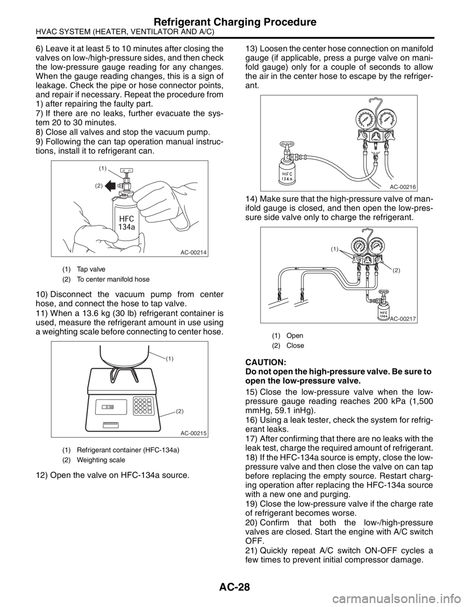
9) Following the can tap operation manual instruc-
tions, install it to refrigerant can.
10) Disconnect the vacuum pump from center
hose, and connect the hose to tap valve.
11) When a 13.6 kg (30 lb) refrigerant container is
used, measure the refrigerant amount in use using
a weighting scale before connecting to center hose.
12) Open the valve on HFC-134a source.13) Loosen the center hose connection on manifold
gauge (if applicable, press a purge valve on mani-
fold gauge) only for a couple of seconds to allow
the air in the center hose to escape by the refriger-
ant.
14) Make sure that the high-pressure valve of man-
ifold gauge is closed, and then open the low-pres-
sure side valve only to charge the refrigerant.
CAUTION:
Do not open the high-pressure valve. Be sure to
open the low-pressure valve.
15) Close the low-pressure valve when the low-
pressure gauge reading reaches 200 kPa (1,500
mmHg, 59.1 inHg).
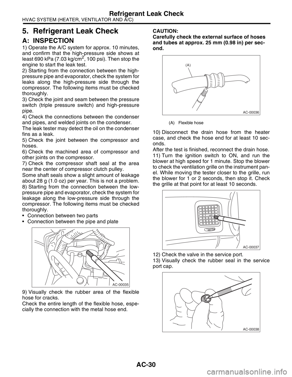
16) Using a leak tester, check the system for refrig-
erant leaks.
17) After confirming that there are no leaks with the
leak test, charge the required amount of refrigerant.
18) If the HFC-134a source is empty, close the low-
pressure valve and then close the valve on can tap
before replacing the empty source. Restart charg-
ing operation after replacing the HFC-134a source
with a new one and purging.
19) Close the low-pressure valve if the charge rate
of refrigerant becomes worse.
20) Confirm that both the low-/high-pressure
valves are closed. Start the engine with A/C switch
OFF.
21) Quickly repeat A/C switch ON-OFF cycles a
few times to prevent initial compressor damage.
(1) Tap valve
(2) To center manifold hose
(1) Refrigerant container (HFC-134a)
(2) Weighting scale
AC-00214
(1)
(2)
AC-00215
(1)
(2)
(1) Open
(2) Close
AC-00216
AC-00217
(1)
(2)
Page 31 of 2870

AC-29
HVAC SYSTEM (HEATER, VENTILATOR AND A/C)
Refrigerant Charging Procedure
22) Set up the vehicle to the following status:
A/C switch ON
Engine running at 1,500 rpm
Blower speed setting to “HI”
Temperature setting to “MAX COOL”
Air inlet setting to “RECIRC”
Window open
23) Open the low-pressure valve and charge the
specified amount of refrigerant.
24) Close all valves and disconnect the hoses from
service port after charging the refrigerant.
25) Install the cap to service port.
Page 32 of 2870

AC-30
HVAC SYSTEM (HEATER, VENTILATOR AND A/C)
Refrigerant Leak Check
5. Refrigerant Leak Check
A: INSPECTION
1) Operate the A/C system for approx. 10 minutes,
and confirm that the high-pressure side shows at
least 690 kPa (7.03 kg/cm
2, 100 psi). Then stop the
engine to start the leak test.
2) Starting from the connection between the high-
pressure pipe and evaporator, check the system for
leaks along the high-pressure side through the
compressor. The following items must be checked
thoroughly.
3) Check the joint and seam between the pressure
switch (triple pressure switch) and high-pressure
pipe.
4) Check the connections between the condenser
and pipes, and welded joints on the condenser.
The leak tester may detect the oil on the condenser
fins as a leak.
5) Check the joint between the compressor and
hoses.
6) Check the machined area of compressor and
other joints on the compressor.
7) Check the compressor shaft seal at the area
near the center of compressor clutch pulley.
Some shaft seals show a slight amount of leakage
about 28 g (1.0 oz) per year. This is not a problem.
8) Starting from the connection between the low-
pressure pipe and evaporator, check the system for
leakage along the low-pressure side through the
compressor. The following items must be checked
thoroughly.
Connection between two parts
Connection between the pipe and plate
9) Visually check the rubber area of the flexible
hose for cracks.
Check the entire length of the flexible hose, espe-
cially the connection with the metal hose end.CAUTION:
Carefully check the external surface of hoses
and tubes at approx. 25 mm (0.98 in) per sec-
ond.
10) Disconnect the drain hose from the heater
case, and check the hose end for at least 10 sec-
onds.
After the test is finished, reconnect the drain hose.
11) Turn the ignition switch to ON, and run the
blower at high speed for 1 minute. Stop the blower
to check the ventilation grille on the instrument pan-
el. While moving the tester closer to the grille, run
the blower for 1 or 2 seconds, then stop it. Check
the grille at that point for at least 10 seconds.
12) Check the valve in the service port.
13) Visually check the rubber seal in the service
port cap.
AC-00035
(A) Flexible hose
AC-00036
(A)
AC-00037
AC-00038
Page 33 of 2870

AC-31
HVAC SYSTEM (HEATER, VENTILATOR AND A/C)
Compressor Oil
6. Compressor Oil
A: OPERATION
NOTE:
Before making repairs, conduct the oil return oper-
ation to return the compressor oil in circulation with
the refrigerant to the compressor.
1) Increase the engine speed to 1,500 rpm.
2) Turn ON the A/C switch.
3) Turn the temperature control dial to MAX COOL.
4) Set the air inlet select switch to RECIRC posi-
tion.
5) Turn the fan dial to HI.
6) Leave in this condition for 10 minutes.
B: REPLACEMENT
NOTE:
If a component is replaced, add an appropriate
amount of compressor oil (same as the amount of
remaining oil in removed component).
When replacing the compressor, the new com-
pressor will already have the specified amount of
oil in it. Install the new compressor after removing
the same amount of oil that is remaining in the com-
pressor removed.
Replacement parts Amount of oil replenishment
EvaporatorApprox. 50 cm
3
(1.7 US fl oz, 1.8 Imp fl oz)
CondenserApprox. 30 cm
3
(1.0 US fl oz, 1.1 Imp fl oz)
HoseApprox. 10 cm
3
(0.4 US fl oz, 0.4 Imp fl oz)
Receiver dryerApprox. 10 cm
3
(0.4 US fl oz, 0.4 Imp fl oz)
Page 38 of 2870

AC-36
HVAC SYSTEM (HEATER, VENTILATOR AND A/C)
Compressor
11.Compressor
A: INSPECTION
1. MAGNETIC CLUTCH CLEARANCE
1) Check the clearance of the entire circumference
around the drive plate and pulley.
Standard:
0.3 — 0.6 mm (0.0118 — 0.0236 in)
2. MAGNETIC CLUTCH OPERATION
1) Disconnect the compressor connector.
2) Connect the battery positive (+) terminal to the
No. 3 terminal of the compressor connector.
3) Make sure the magnet clutch engages.
If NG, replace the compressor.
B: REMOVAL
1) Perform the compressor oil return operation.
2) Turn the A/C switch OFF and stop the engine.
3) Using the refrigerant recovery system, discharge
refrigerant.
4) Disconnect the ground cable from battery.
5) Remove the V-belt.
6) Remove the generator.
7) Remove the low-pressure hose and high-pres-
sure hose.
8) Disconnect the compressor harness from body
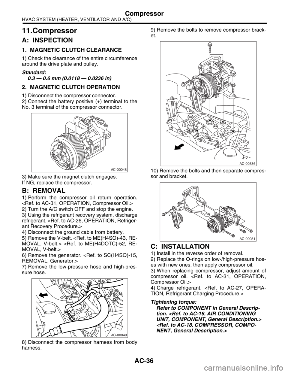
harness.9) Remove the bolts to remove compressor brack-
et.
10) Remove the bolts and then separate compres-
sor and bracket.
C: INSTALLATION
1) Install in the reverse order of removal.
2) Replace the O-rings on low-/high-pressure hos-
es with new ones, then apply compressor oil.
3) When replacing compressor, adjust amount of
compressor oil.
4) Charge refrigerant.
Tightening torque:
Refer to COMPONENT in General Descrip-
tion.
AC-00048
AC-00049
AC-00336
AC-00051
Page 726 of 2870

PI-3
PRE-DELIVERY INSPECTION
Pre-delivery Inspection
B: PDI PROCEDURE
Follow the procedures shown in the table below.
Static Checks Just After Vehicle Receipt
Step Check point
1. Appearance check (1) If the vehicle is covered with protective coating, visually check the vehicle
body for damage and dents. If the protective coating has been removed,
visually check the body paints for small areas of damage or stains.
(2) Visually check the glass and light lenses for any damage and cracks or
excessive gaps to the body sheet metal.
(3) Visually check the plated parts for any damage.
2. Tire check (1) Check the tires for damage, abnormal conditions, and dents on the
wheels.
(2) Check the tire air pressure.
3. Fuse installation If the vehicle is about to be delivered to the customer, attach a room light
fuse.
4. Connection of air conditioner harness If the vehicle is about to be delivered to the customer, connect the air condi-
tioner harness.
5. Check the doors for lock/unlock and open/close
operations.(1) Using the key, check if the door can be locked and unlocked normally.
(2) Open and close all doors to see that there are no abnormal conditions.
6. Operation check of double lock Check that the double lock operates normally.
7. Operation check of the child safety lock system. Check the child safety lock system operates normally.
8. Check the rear gate for lock/unlock and open/
close operations.(1) Check if the rear gate can be unlocked normally from the emergency
door.
(2) Open and close the rear gate to see that there are no abnormal condi-
tions.
(3) Operate the power door locking switch to check that the rear gate is
locked and unlocked normally.
9. Operation check of fuel lid opener lock release
leverOperate the fuel lid opener to check that the fuel lid is unlocked normally.
10. Accessory check Check that the following accessories are provided:
Owner’s manual
Warranty booklet
Service booklet
Spare key
Jack
Tool set
Spare tire
11. Operation check of hood lock release system Operate the hood lock release lever to check that the hood opens normally.
12. Battery Check the battery for any abnormal conditions such as rust and trace of bat-
tery fluid leaks.
13. Brake fluid Check the fluid amount.
14. Engine oil Check the oil amount.
15. Transmission fluid (1) Check the fluid amount.
(2) For AT, check the front differential oil.
16. AT front differential oil Check the AT front differential oil amount.
17. Coolant Check the coolant amount.
18. Clutch fluid Check the clutch fluid amount.
19. Window washer fluid Check the window washer fluid amount.
20. Hood latch check Check that the hood is closed and latched securely.
21. Keyless entry system Check that the keyless entry system operates normally.
22. Security system Check that the security system operates normally.
23. Seat (1) Check the seat surfaces for smears or dirt.
(2) Check the seat installation conditions and functionality.
24. Seat belt Check the seat belt installation conditions and functionality.
25. Wheel alignment Check that the wheel alignments are properly adjusted.
Page 731 of 2870

PI-8
PRE-DELIVERY INSPECTION
Pre-delivery Inspection
11.OPERATION CHECK OF HOOD LOCK
RELEASE SYSTEM
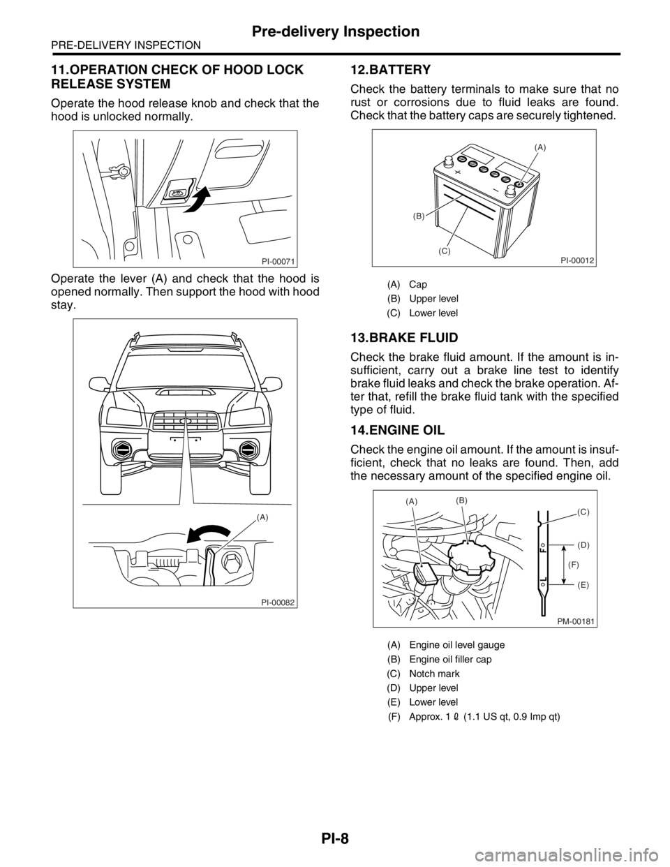
Operate the hood release knob and check that the
hood is unlocked normally.
Operate the lever (A) and check that the hood is
opened normally. Then support the hood with hood
stay.
12.BATTERY
Check the battery terminals to make sure that no
rust or corrosions due to fluid leaks are found.
Check that the battery caps are securely tightened.
13.BRAKE FLUID
Check the brake fluid amount. If the amount is in-
sufficient, carry out a brake line test to identify
brake fluid leaks and check the brake operation. Af-
ter that, refill the brake fluid tank with the specified
type of fluid.
14.ENGINE OIL
Check the engine oil amount. If the amount is insuf-
ficient, check that no leaks are found. Then, add
the necessary amount of the specified engine oil.
PI-00071
PI-00082
(A)
(A) Cap
(B) Upper level
(C) Lower level
(A) Engine oil level gauge
(B) Engine oil filler cap
(C) Notch mark
(D) Upper level
(E) Lower level
(F) Approx. 12 (1.1 US qt, 0.9 Imp qt)
PI-00012
(A)
(B)
(C)
PM-00181
(A)(B)
(D)
(E) (F)(C)