2004 SUBARU FORESTER Engine mount
[x] Cancel search: Engine mountPage 759 of 2870
PM-22
PERIODIC MAINTENANCE SERVICE
Engine Coolant
2. RELATIONSHIP OF SUBARU COOLANT
CONCENTRATION AND FREEZING TEM-
PERATURE
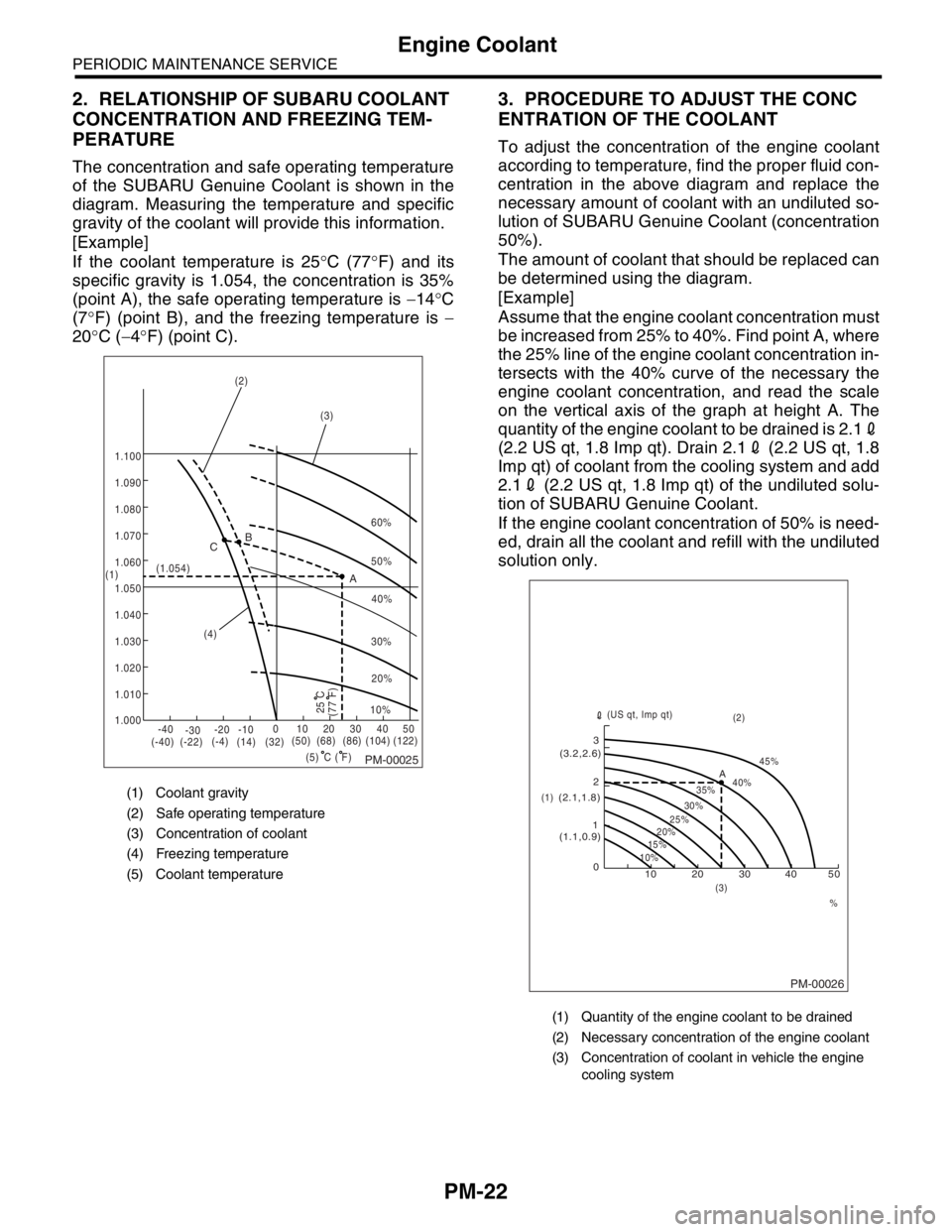
The concentration and safe operating temperature
of the SUBARU Genuine Coolant is shown in the
diagram. Measuring the temperature and specific
gravity of the coolant will provide this information.
[Example]
If the coolant temperature is 25°C (77°F) and its
specific gravity is 1.054, the concentration is 35%
(point A), the safe operating temperature is −14°C
(7°F) (point B), and the freezing temperature is −
20°C (−4°F) (point C).
3. PROCEDURE TO ADJUST THE CONC
ENTRATION OF THE COOLANT
To adjust the concentration of the engine coolant
according to temperature, find the proper fluid con-
centration in the above diagram and replace the
necessary amount of coolant with an undiluted so-
lution of SUBARU Genuine Coolant (concentration
50%).
The amount of coolant that should be replaced can
be determined using the diagram.
[Example]
Assume that the engine coolant concentration must
be increased from 25% to 40%. Find point A, where
the 25% line of the engine coolant concentration in-
tersects with the 40% curve of the necessary the
engine coolant concentration, and read the scale
on the vertical axis of the graph at height A. The
quantity of the engine coolant to be drained is 2.12
(2.2 US qt, 1.8 Imp qt). Drain 2.12 (2.2 US qt, 1.8
Imp qt) of coolant from the cooling system and add
2.12 (2.2 US qt, 1.8 Imp qt) of the undiluted solu-
tion of SUBARU Genuine Coolant.
If the engine coolant concentration of 50% is need-
ed, drain all the coolant and refill with the undiluted
solution only.
(1) Coolant gravity
(2) Safe operating temperature
(3) Concentration of coolant
(4) Freezing temperature
(5) Coolant temperature
PM-00025
60%
(1.054)
1.000 1.010 1.020
1.030
1.040
1.050
1.060
1.070 1.080 1.090
1.100
(5) (4)(3) (2)
(1)B
A C
-40
(-40) (-22)(-4)
(14)(32)(50) (68) (86)
( F)(104) (122) -30-20 -1001020304050
(77 F)
50%
40%
30%
20%
25 C10%
C
(1) Quantity of the engine coolant to be drained
(2) Necessary concentration of the engine coolant
(3) Concentration of coolant in vehicle the engine
cooling system
PM-00026
10 0 12 3
(1.1,0.9) (2.1,1.8)(3.2,2.6)
10%15%25%
20%30%35%40%45%
A
20 30 40 50
% (3)(2)
(1)(US qt, Imp qt)
Page 763 of 2870
PM-26
PERIODIC MAINTENANCE SERVICE
ATF
16.ATF
A: INSPECTION
CAUTION:
The level of ATF varies with fluid temperature.
Pay attention to the fluid temperature when
checking ATF level.
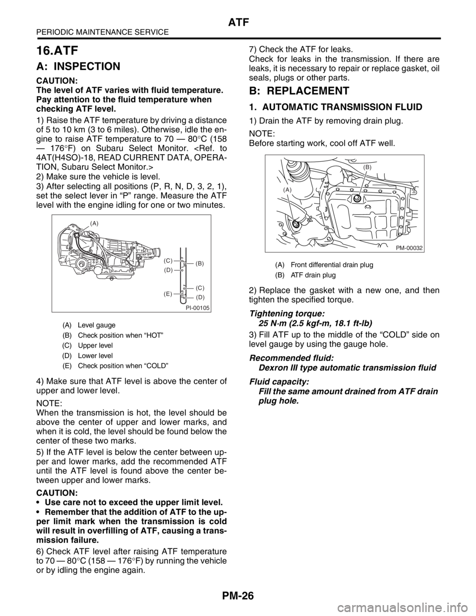
1) Raise the ATF temperature by driving a distance
of 5 to 10 km (3 to 6 miles). Otherwise, idle the en-
gine to raise ATF temperature to 70 — 80°C (158
— 176°F) on Subaru Select Monitor.
TION, Subaru Select Monitor.>
2) Make sure the vehicle is level.
3) After selecting all positions (P, R, N, D, 3, 2, 1),
set the select lever in “P” range. Measure the ATF
level with the engine idling for one or two minutes.
4) Make sure that ATF level is above the center of
upper and lower level.
NOTE:
When the transmission is hot, the level should be
above the center of upper and lower marks, and
when it is cold, the level should be found below the
center of these two marks.
5) If the ATF level is below the center between up-
per and lower marks, add the recommended ATF
until the ATF level is found above the center be-
tween upper and lower marks.
CAUTION:
Use care not to exceed the upper limit level.
Remember that the addition of ATF to the up-
per limit mark when the transmission is cold
will result in overfilling of ATF, causing a trans-
mission failure.
6) Check ATF level after raising ATF temperature
to 70 — 80°C (158 — 176°F) by running the vehicle
or by idling the engine again.7) Check the ATF for leaks.
Check for leaks in the transmission. If there are
leaks, it is necessary to repair or replace gasket, oil
seals, plugs or other parts.
B: REPLACEMENT
1. AUTOMATIC TRANSMISSION FLUID
1) Drain the ATF by removing drain plug.
NOTE:
Before starting work, cool off ATF well.
2) Replace the gasket with a new one, and then
tighten the specified torque.
Tightening torque:
25 N·m (2.5 kgf-m, 18.1 ft-lb)
3) Fill ATF up to the middle of the “COLD” side on
level gauge by using the gauge hole.
Recommended fluid:
Dexron III type automatic transmission fluid
Fluid capacity:
Fill the same amount drained from ATF drain
plug hole.
(A) Level gauge
(B) Check position when “HOT”
(C) Upper level
(D) Lower level
(E) Check position when “COLD”
PI-00105
COLD
LFHOT LF
(A)
(C)
(D)
(C)
(D)
(E)
(B)(A) Front differential drain plug
(B) ATF drain plug
PM-00032
(B)
(A)
Page 870 of 2870

MECHANICAL
ME(H4SO)
Page
1. General Description ....................................................................................2
2. Compression .............................................................................................25
3. Idle Speed .................................................................................................26
4. Ignition Timing ...........................................................................................27
5. Intake Manifold Vacuum............................................................................28
6. Engine Oil Pressure ..................................................................................29
7. Fuel Pressure ............................................................................................30
8. Valve Clearance ........................................................................................31
9. Engine Assembly ......................................................................................34
10. Engine Mounting .......................................................................................41
11. Preparation for Overhaul ...........................................................................42
12. V-belt .........................................................................................................43
13. Crank Pulley ..............................................................................................45
14. Timing Belt Cover......................................................................................47
15. Timing Belt ................................................................................................48
16. Cam Sprocket ...........................................................................................53
17. Crank Sprocket .........................................................................................55
18. Valve Rocker Assembly ............................................................................56
19. Camshaft ...................................................................................................58
20. Cylinder Head ...........................................................................................62
21. Cylinder Block ...........................................................................................69
22. Engine Trouble in General ........................................................................91
23. Engine Noise .............................................................................................96
Page 883 of 2870
ME(H4SO)-14
MECHANICAL
General Description
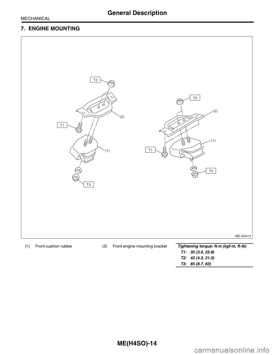
7. ENGINE MOUNTING
(1) Front cushion rubber (2) Front engine mounting bracketTightening torque: N⋅m (kgf-m, ft-lb)
T1: 35 (3.6, 25.8)
T2: 42 (4.3, 31.0)
T3: 85 (8.7, 63)
ME-00413
T2
T1
T1
T3
T3 (2)(2)
(1)(1)
T2
Page 907 of 2870
ME(H4SO)-38
MECHANICAL
Engine Assembly
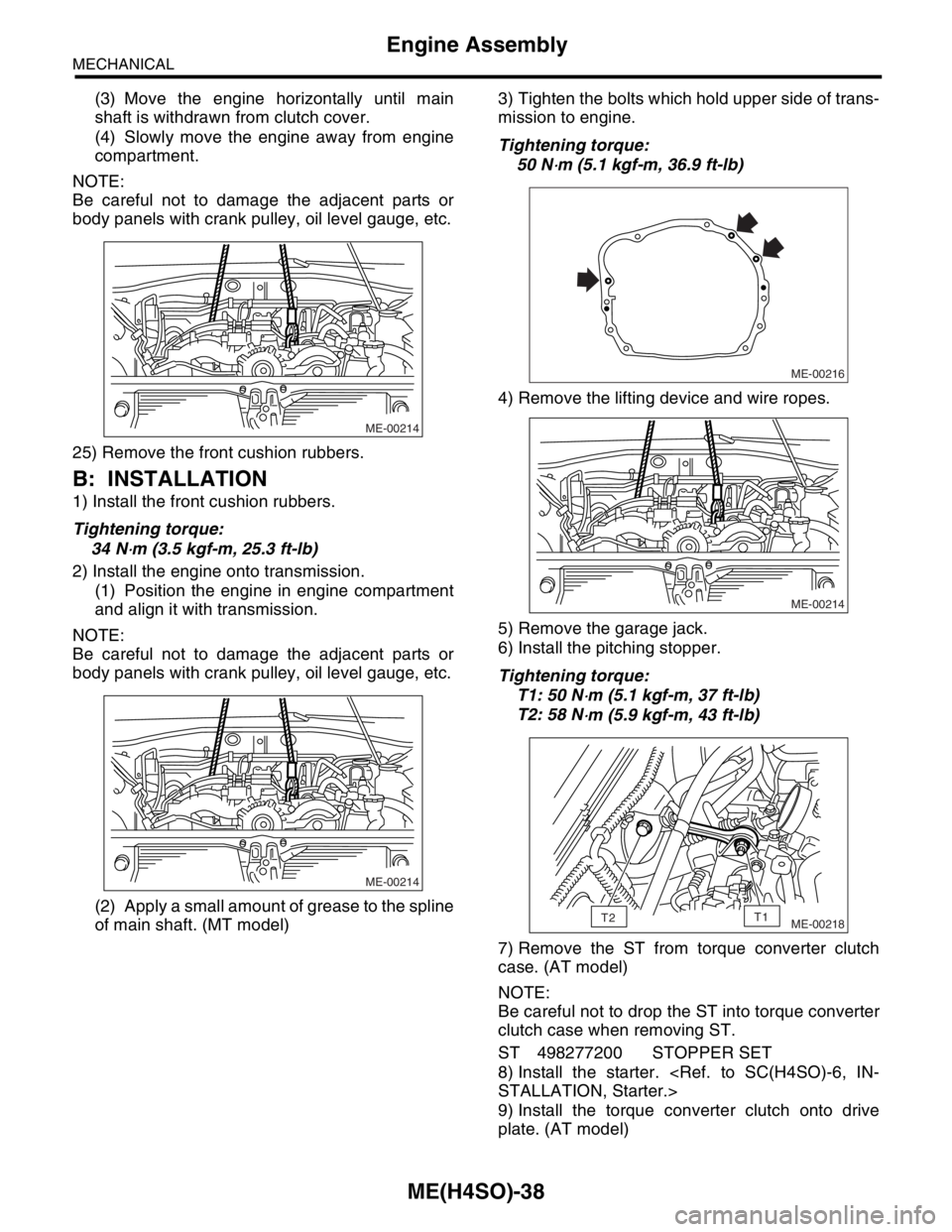
(3) Move the engine horizontally until main
shaft is withdrawn from clutch cover.
(4) Slowly move the engine away from engine
compartment.
NOTE:
Be careful not to damage the adjacent parts or
body panels with crank pulley, oil level gauge, etc.
25) Remove the front cushion rubbers.
B: INSTALLATION
1) Install the front cushion rubbers.
Tightening torque:
34 N
⋅m (3.5 kgf-m, 25.3 ft-lb)
2) Install the engine onto transmission.
(1) Position the engine in engine compartment
and align it with transmission.
NOTE:
Be careful not to damage the adjacent parts or
body panels with crank pulley, oil level gauge, etc.
(2) Apply a small amount of grease to the spline
of main shaft. (MT model)3) Tighten the bolts which hold upper side of trans-
mission to engine.
Tightening torque:
50 N
⋅m (5.1 kgf-m, 36.9 ft-lb)
4) Remove the lifting device and wire ropes.
5) Remove the garage jack.
6) Install the pitching stopper.
Tightening torque:
T1: 50 N
⋅m (5.1 kgf-m, 37 ft-lb)
T2: 58 N
⋅m (5.9 kgf-m, 43 ft-lb)
7) Remove the ST from torque converter clutch
case. (AT model)
NOTE:
Be careful not to drop the ST into torque converter
clutch case when removing ST.
ST 498277200 STOPPER SET
8) Install the starter.
9) Install the torque converter clutch onto drive
plate. (AT model)
ME-00214
ME-00214
ME-00216
ME-00214
ME-00218T2T1
Page 909 of 2870
ME(H4SO)-40
MECHANICAL
Engine Assembly
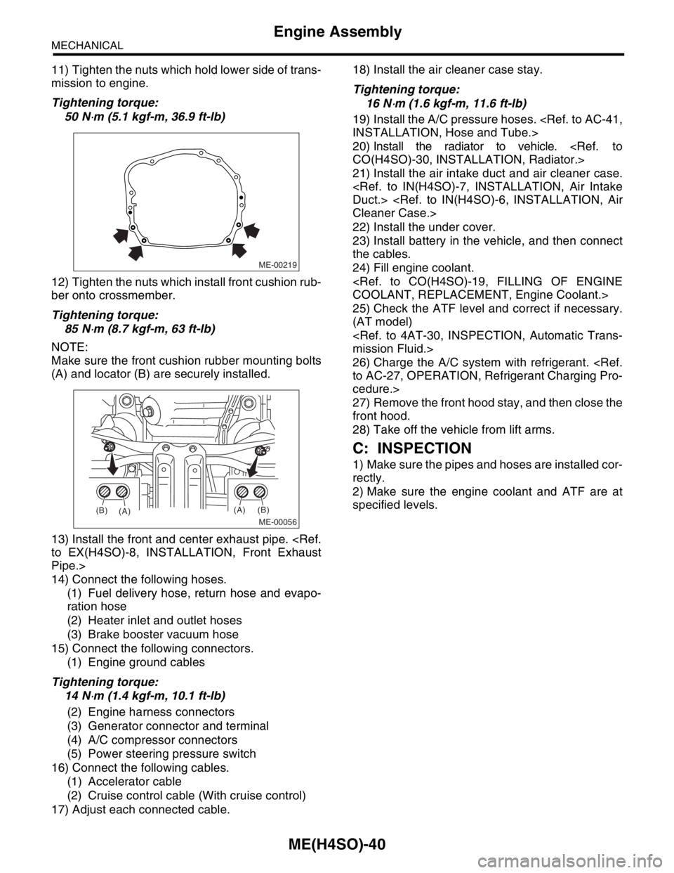
11) Tighten the nuts which hold lower side of trans-
mission to engine.
Tightening torque:
50 N
⋅m (5.1 kgf-m, 36.9 ft-lb)
12) Tighten the nuts which install front cushion rub-
ber onto crossmember.
Tightening torque:
85 N
⋅m (8.7 kgf-m, 63 ft-lb)
NOTE:
Make sure the front cushion rubber mounting bolts
(A) and locator (B) are securely installed.
13) Install the front and center exhaust pipe.
Pipe.>
14) Connect the following hoses.
(1) Fuel delivery hose, return hose and evapo-
ration hose
(2) Heater inlet and outlet hoses
(3) Brake booster vacuum hose
15) Connect the following connectors.
(1) Engine ground cables
Tightening torque:
14 N
⋅m (1.4 kgf-m, 10.1 ft-lb)
(2) Engine harness connectors
(3) Generator connector and terminal
(4) A/C compressor connectors
(5) Power steering pressure switch
16) Connect the following cables.
(1) Accelerator cable
(2) Cruise control cable (With cruise control)
17) Adjust each connected cable.18) Install the air cleaner case stay.
Tightening torque:
16 N
⋅m (1.6 kgf-m, 11.6 ft-lb)
19) Install the A/C pressure hoses.
20) Install the radiator to vehicle.
21) Install the air intake duct and air cleaner case.
22) Install the under cover.
23) Install battery in the vehicle, and then connect
the cables.
24) Fill engine coolant.
25) Check the ATF level and correct if necessary.
(AT model)
26) Charge the A/C system with refrigerant.
cedure.>
27) Remove the front hood stay, and then close the
front hood.
28) Take off the vehicle from lift arms.
C: INSPECTION
1) Make sure the pipes and hoses are installed cor-
rectly.
2) Make sure the engine coolant and ATF are at
specified levels.
ME-00219
ME-00056
(A)
(A)(B)
(B)
Page 910 of 2870

ME(H4SO)-41
MECHANICAL
Engine Mounting
10.Engine Mounting
A: REMOVAL
1) Remove the engine assembly.
2) Remove the engine mounting from engine as-
sembly.
B: INSTALLATION
Install in the reverse order of removal.
Tightening torque:
Engine mounting:
34 N
⋅m (3.5 kgf-m, 25.3 ft-lb)
C: INSPECTION
Make sure there are no cracks or other damage.
Page 923 of 2870

MECHANICAL
ME(H4SO)
Page
1. General Description ....................................................................................2
2. Compression .............................................................................................25
3. Idle Speed .................................................................................................26
4. Ignition Timing ...........................................................................................27
5. Intake Manifold Vacuum............................................................................28
6. Engine Oil Pressure ..................................................................................29
7. Fuel Pressure ............................................................................................30
8. Valve Clearance ........................................................................................31
9. Engine Assembly ......................................................................................34
10. Engine Mounting .......................................................................................41
11. Preparation for Overhaul ...........................................................................42
12. V-belt .........................................................................................................43
13. Crank Pulley ..............................................................................................45
14. Timing Belt Cover......................................................................................47
15. Timing Belt ................................................................................................48
16. Cam Sprocket ...........................................................................................53
17. Crank Sprocket .........................................................................................55
18. Valve Rocker Assembly ............................................................................56
19. Camshaft ...................................................................................................58
20. Cylinder Head ...........................................................................................62
21. Cylinder Block ...........................................................................................69
22. Engine Trouble in General ........................................................................91
23. Engine Noise .............................................................................................96