Page 44 of 2870
AC-42
HVAC SYSTEM (HEATER, VENTILATOR AND A/C)
Relay and Fuse
17.Relay and Fuse
A: LOCATIONB: INSPECTION
While applying battery voltage between the termi-
nals (1) and (2), check continuity between the ter-
minals (3) and (5).
If no continuity exists, replace the relay with a new
one.
(1) Main fuse box (M/B)
(2) Main fan relay
(3) Sub fan relay
(4) A/C relay
(5) Fan mode relay
(6) Main fan fuse
(7) Sub fan fuse
AC-00834
(7) (6) (5) (4)(1) (3) (2)
(1) — (2) Continuity exists.
(3) — (4) Continuity exists.
(3) — (5) No continuity.
AC-00093
4
4
5
2
25
3
3
1
1
Page 115 of 2870

AB-15
AIRBAG SYSTEM
Passenger’s Airbag Module
5. Passenger’s Airbag Module
A: REMOVAL
CAUTION:
Refer to “CAUTION” in General Description be-
fore handing the airbag module.
CAUTION, General Description.>
1) Turn the ignition switch to OFF.
2) Disconnect the ground cable from battery, and
wait for at least 20 seconds before starting work.
3) Remove the glove box.
AL, Glove Box.>
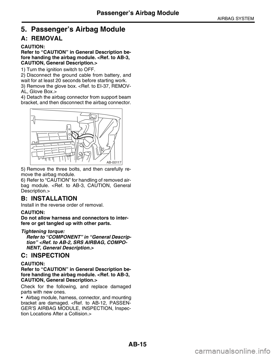
4) Detach the airbag connector from support beam
bracket, and then disconnect the airbag connector.
5) Remove the three bolts, and then carefully re-
move the airbag module.
6) Refer to “CAUTION” for handling of removed air-
bag module.
Description.>
B: INSTALLATION
Install in the reverse order of removal.
CAUTION:
Do not allow harness and connectors to inter-
fere or get tangled up with other parts.
Tightening torque:
Refer to “COMPONENT” in “General Descrip-
tion”
NENT, General Description.>
C: INSPECTION
CAUTION:
Refer to “CAUTION” in General Description be-
fore handing the airbag module.
CAUTION, General Description.>
Check for the following, and replace damaged
parts with new ones.
Airbag module, harness, connector, and mounting
bracket are damaged.
GER’S AIRBAG MODULE, INSPECTION, Inspec-
tion Locations After a Collision.>
AB-00117
Page 517 of 2870

EI-41
EXTERIOR/INTERIOR TRIM
Instrument Panel Assembly
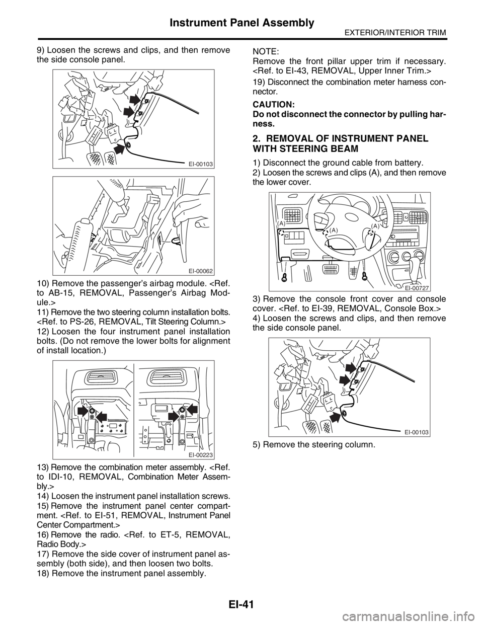
9) Loosen the screws and clips, and then remove
the side console panel.
10) Remove the passenger’s airbag module.
to AB-15, REMOVAL, Passenger’s Airbag Mod-
ule.>
11) Remove the two steering column installation bolts.
12) Loosen the four instrument panel installation
bolts. (Do not remove the lower bolts for alignment
of install location.)
13) Remove the combination meter assembly.
to IDI-10, REMOVAL, Combination Meter Assem-
bly.>
14) Loosen the instrument panel installation screws.
15) Remove the instrument panel center compart-
ment.
Center Compartment.>
16) Remove the radio.
Radio Body.>
17) Remove the side cover of instrument panel as-
sembly (both side), and then loosen two bolts.
18) Remove the instrument panel assembly.NOTE:
Remove the front pillar upper trim if necessary.
19) Disconnect the combination meter harness con-
nector.
CAUTION:
Do not disconnect the connector by pulling har-
ness.
2. REMOVAL OF INSTRUMENT PANEL
WITH STEERING BEAM
1) Disconnect the ground cable from battery.
2) Loosen the screws and clips (A), and then remove
the lower cover.
3) Remove the console front cover and console
cover.
4) Loosen the screws and clips, and then remove
the side console panel.
5) Remove the steering column.EI-00103
EI-00062
EI-00223
EI-00727
(A)
(A)(A)
EI-00103
Page 703 of 2870

NT-2
NOTE
Note
1. Note
A: NOTE
This is information that can improve efficiency of
maintenance and assure sound work.
1. FASTENER NOTICE
Fasteners are used to prevent parts from damage
and dislocation due to looseness. Fasteners must
be tightened to the specified torque.
Do not apply paint, lubricant, rust retardant, or oth-
er substances to the surface around bolts, fasten-
ers, etc. Doing so will make it difficult to obtain the
correct torque and result in looseness and other
problems.
2. STATIC ELECTRICITY DAMAGE
Do not touch the control unit, connectors, logic
boards, and other such parts when there is a risk of
static electricity. Always use a static electricity pre-
vention cord or touch grounded metal before con-
ducting work.
3. BATTERY
When removing the battery cables, always be sure
to turn the ignition switch off to prevent electrical
damage to the control unit from rush current.
4. SERVICE PARTS
Use authentic service parts for maximum perfor-
mance and maintenance, when conducting repairs.
Subaru/FHI will not be responsible for poor perfor-
mance resulting from the use of parts not specified
by a genuine dealer.
5. PROTECTING VEHICLE UNDER MAIN-
TENANCE
Make sure to attach the fender cover, seat covers,
etc. before work.
6. ENSURING SAFETY DURING WORK
When working in a group of two or more, perform
the work with calling each other to ensure mutual
safety.