Page 730 of 2870
PI-7
PRE-DELIVERY INSPECTION
Pre-delivery Inspection
8. CHECK THE REAR GATE FOR LOCK/
UNLOCK AND OPEN/CLOSE OPERA-
TIONS.
1) Open and close the rear gate several times for
smooth movement.
2) Operate the rear gate lever to check that the rear
gate is locked and unlocked normally.
(1) Remove the blind cover inside the rear gate.
(2) Using a screwdriver, check the rear gate is
lock/unlock.
9. OPERATION CHECK OF FUEL LID
OPENER LOCK RELEASE LEVER
Operate the fuel lid opener and verify that the fuel
lid opens normally. Check that the filler cap is se-
curely closed.
10.ACCESSORY CHECK
Check that the following accessories are provided
in the luggage compartment or cargo area.
Owner’s manual
Warranty booklet
Service booklet
Spare key
Jack
Tool set
Spare tire
PI-00006
PI-00007
(A) Jack
(A) Jack handle
PI-00008
(A)
PI-00009(A)
Page 796 of 2870

FU(H4SO)-14
FUEL INJECTION (FUEL SYSTEM)
Intake Manifold
3. Intake Manifold
A: REMOVAL
1) Release the fuel pressure.
47, RELEASING OF FUEL PRESSURE, OPERA-
TION, Fuel.>
2) Open the fuel flap lid, and remove the fuel filler
cap.
3) Disconnect the ground cable from battery.
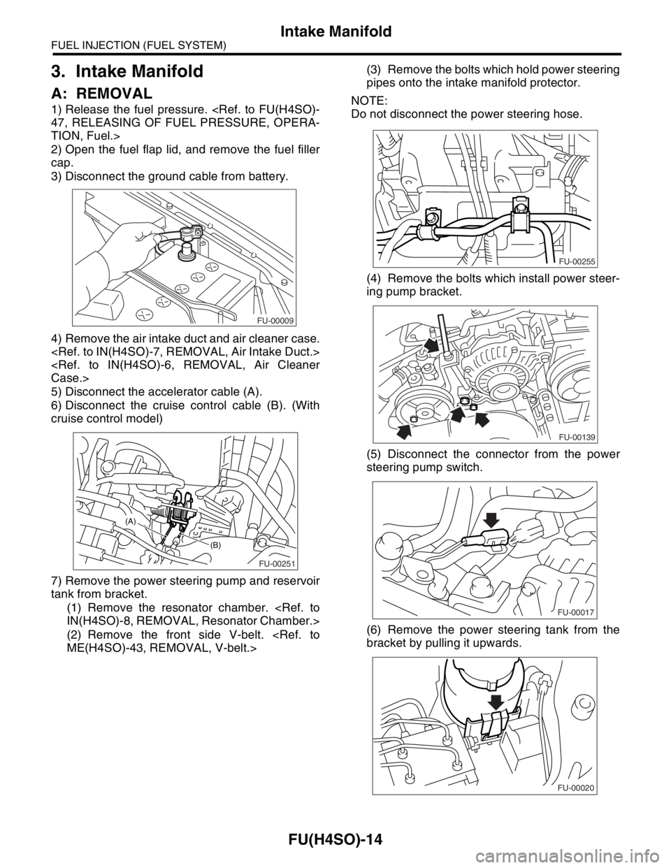
4) Remove the air intake duct and air cleaner case.
Case.>
5) Disconnect the accelerator cable (A).
6) Disconnect the cruise control cable (B). (With
cruise control model)
7) Remove the power steering pump and reservoir
tank from bracket.
(1) Remove the resonator chamber.
IN(H4SO)-8, REMOVAL, Resonator Chamber.>
(2) Remove the front side V-belt.
ME(H4SO)-43, REMOVAL, V-belt.>(3) Remove the bolts which hold power steering
pipes onto the intake manifold protector.
NOTE:
Do not disconnect the power steering hose.
(4) Remove the bolts which install power steer-
ing pump bracket.
(5) Disconnect the connector from the power
steering pump switch.
(6) Remove the power steering tank from the
bracket by pulling it upwards.
FU-00009
FU-00251
(B)
(A)
FU-00255
FU-00139
FU-00017
FU-00020
Page 817 of 2870
FU(H4SO)-35
FUEL INJECTION (FUEL SYSTEM)
Fuel Injector
13.Fuel Injector
A: REMOVAL
1. RH SIDE
1) Release the fuel pressure.
PRESSURE, OPERATION, Fuel.>
2) Open the fuel flap lid, and remove the fuel filler
cap.
3) Disconnect the ground cable from battery.
4) Remove the resonator chamber.
IN(H4SO)-8, REMOVAL, Resonator Chamber.>
5) Remove the spark plug cords from the spark
plugs (#1 and #3 cylinders).6) Remove the power steering pump and reservoir
tank from the brackets.
(1) Remove the front side V-belt.
ME(H4SO)-43, REMOVAL, V-belt.>
(2) Remove the bolts which hold the power
steering pipes onto the intake manifold protec-
tor.
(3) Remove the bolts which install the power
steering pump to the bracket.
(4) Disconnect the connector from the power
steering pump switch.
FU-00009
FU-00302
FU-00255
FU-00139
FU-00017
Page 819 of 2870
FU(H4SO)-37
FUEL INJECTION (FUEL SYSTEM)
Fuel Injector
2. LH SIDE
1) Release the fuel pressure.
47, RELEASING OF FUEL PRESSURE, OPERA-
TION, Fuel.>
2) Open the fuel flap lid, and remove the fuel filler
cap.
3) Disconnect the ground cable from battery.
4) Remove the two bolts which install the washer
tank on the body.
5) Disconnect the connector from the front window
washer motor.
6) Disconnect the connector from the rear gate
glass washer motor.
7) Disconnect the rear window glass washer hose
from the washer motor, then plug the connection
with a suitable cap.8) Move the washer tank, and secure it away from
the working area.
9) Remove the spark plug cords from the spark
plugs (#2 and #4 cylinders).
10) Remove the fuel pipe protector LH.
11) Disconnect the connector from the fuel injector.
FU-00009
FU-00190
FU-00191
FU-00192
FU-00307
FU-00266
FU-00308
Page 833 of 2870
FU(H4SO)-51
FUEL INJECTION (FUEL SYSTEM)
Fuel Filler Pipe
21.Fuel Filler Pipe
A: REMOVAL
WARNING:
Place “NO FIRE” signs near the working area.
Be careful not to spill fuel.
1) Set the vehicle on a lift.
2) Release the fuel pressure.
47, RELEASING OF FUEL PRESSURE, OPERA-
TION, Fuel.>
3) Open the fuel filler flap lid and remove fuel filler
cap.
4) Disconnect the ground cable from battery.
5) Remove the screws holding packing in place.
6) Loosen the rear right side wheel nuts.
7) Lift-up the vehicle.
8) Remove the rear right side wheel.9) Drain fuel from the fuel tank. Set a container un-
der the vehicle and remove the drain plug from fuel
tank.
10) Tighten the fuel drain plug and then install the
front right side tank cover.
Tightening torque:
26 N
⋅m (2.7 kgf-m, 19.2 ft-lb)
11) Remove the fuel filler pipe protector.
12) Separate the evaporation hoses from clip of
fuel filler pipe.
FU-00009
FU-00095
FU-00096
FU-00089
FU-00089
FU-00097
FU-00098
Page 837 of 2870
FU(H4SO)-55
FUEL INJECTION (FUEL SYSTEM)
Fuel Pump
22.Fuel Pump
A: REMOVAL
WARNING:
Place “NO FIRE” signs near the working area.
Be careful not to spill fuel.
NOTE:
Fuel pump assembly consists of fuel pump and fuel
level sensor.
1) Release the fuel pressure.
47, RELEASING OF FUEL PRESSURE, OPERA-
TION, Fuel.>
2) Open the fuel filler flap lid and remove fuel filler
cap.
3) Disconnect the ground cable from battery.
4) Lift-up the vehicle.
5) Drain fuel from the fuel tank. Set a container un-
der the vehicle and remove the drain plug from fuel
tank.6) Tighten the fuel drain plug.
Tightening torque:
26 N
⋅m (2.7 kgf-m, 19.2 ft-lb)
7) Raise the rear seat and turn floor mat up.
8) Remove the access hole lid.
9) Disconnect the connector from fuel pump.
10) Disconnect the quick connector and then dis-
connect fuel delivery hose.
REMOVAL, Fuel Delivery, Return and Evaporation
Lines.>
FU-00009
FU-00089
FU-00089
FU-00105
FU-00106
Page 845 of 2870
FU(H4SO)-63
FUEL INJECTION (FUEL SYSTEM)
Fuel Delivery, Return and Evaporation Lines
28.Fuel Delivery, Return and Evaporation Lines
A: REMOVAL
1) Set the vehicle on a lift.
2) Release the fuel pressure.
Fuel.>
3) Open the fuel filler flap lid and remove fuel filler cap.
4) Remove the floor mat.
5) Remove the fuel delivery pipes and hoses, fuel return pipes and hoses, evaporation pipes and hoses.
6) In the engine compartment, detach the fuel de-
livery hose (A), return hose (B) and evaporation
hose (C).
7) Lift-up the vehicle.8) Disconnect the two-way valve hose (A) from
two-way valve and disconnect the canister hose (B)
from canister.
FU-00122
(B) (A)
(C)
FU-00374
(A)(B)
FU-00091
Page 899 of 2870

ME(H4SO)-30
MECHANICAL
Fuel Pressure
7. Fuel Pressure
A: INSPECTION
WARNING:
Before removing the fuel pressure gauge, re-
lease the fuel pressure.
NOTE:
If out of specification, check or replace the pressure
regulator and pressure regulator vacuum hose.
1) Release the fuel pressure.
47, RELEASING OF FUEL PRESSURE, OPERA-
TION, Fuel.>
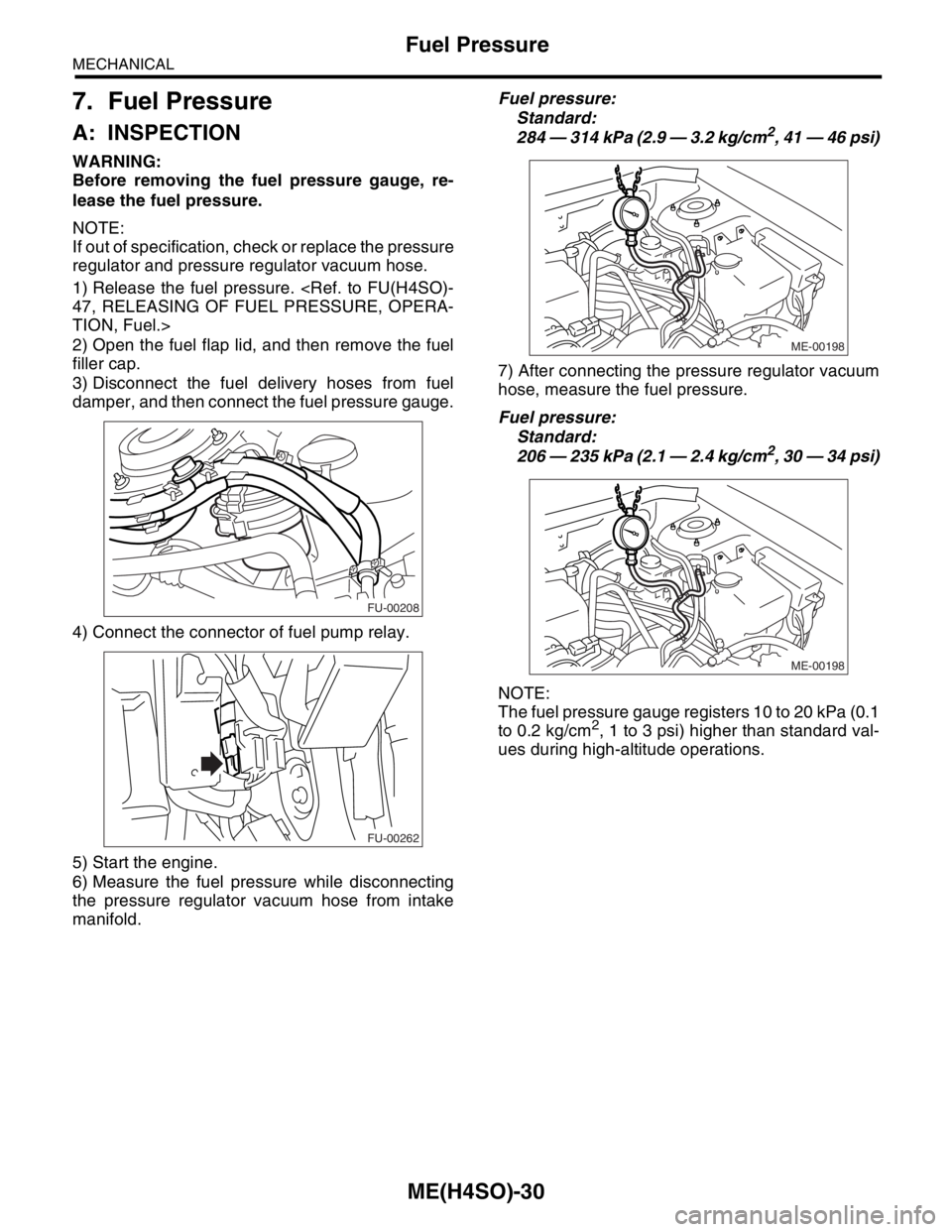
2) Open the fuel flap lid, and then remove the fuel
filler cap.
3) Disconnect the fuel delivery hoses from fuel
damper, and then connect the fuel pressure gauge.
4) Connect the connector of fuel pump relay.
5) Start the engine.
6) Measure the fuel pressure while disconnecting
the pressure regulator vacuum hose from intake
manifold.Fuel pressure:
Standard:
284 — 314 kPa (2.9 — 3.2 kg/cm
2, 41 — 46 psi)
7) After connecting the pressure regulator vacuum
hose, measure the fuel pressure.
Fuel pressure:
Standard:
206 — 235 kPa (2.1 — 2.4 kg/cm
2, 30 — 34 psi)
NOTE:
The fuel pressure gauge registers 10 to 20 kPa (0.1
to 0.2 kg/cm
2, 1 to 3 psi) higher than standard val-
ues during high-altitude operations.
FU-00208
FU-00262
ME-00198
ME-00198