2004 SUBARU FORESTER ABS
[x] Cancel search: ABSPage 112 of 2870

AB-12
AIRBAG SYSTEM
Inspection Locations After a Collision
3. Inspection Locations After a
Collision
A: REPLACEMENT
When airbag system is deployed, replace the fol-
lowing parts.
1. FRONT COLLISION
1) Driver’s airbag module
2) Passenger’s airbag module
3) Driver’s seat belt (pretensioner, lap seat belt pre-
tensioner)
4) Passenger’s seat belt (pretensioner)
5) Airbag control module
6) Front sub-sensor
7) Roll connector
2. SIDE COLLISION
1) Airbag control module
2) Side airbag module (operating side seat bag)
3) Side airbag sensor (operating side)
3. INSPECTION OF OTHER PARTS
Check for the following parts, replace the damaged
parts with new ones.
1) Steering wheel and steering shaft
Check the steering wheel and steering shaft for
mounting condition and deflection of axial and radi-
al direction. Check the steering shaft for deflection
of axial direction with tilt lever released. (After a col-
lision, absorbing part of steering shaft may inflate.)
2) Check the direct type connector of driver’s air-
bag module, pretensioner, etc. for damage, and
also check each harness for pinch and connector
damage. If damage is found, replace the harness
as a unit.
B: INSPECTION
If the vehicle is involved in a collision on any side,
even if it is a slight collision, be sure to check the
following system parts.
1. DRIVER’S AIRBAG MODULE
1) Check for the following, and replace damaged
parts with new ones.
Airbag module is cracked or deformed.
Harness and/or connector is cracked, deformed
or open. Lead wire is exposed.
The module surface is fouled with grease, oil,
water or cleaning solvent.
2) When installing a new driver’s airbag module,
check the following. If necessary, install a new air-
bag module and steering wheel.
The steering wheel is in the way, making it diffi-
cult to install the airbag module. The clearance between the driver’s airbag mod-
ule and steering wheel is not constant.
The steering wheel deformation in axial and radi-
al directions exceed limits.
Specifications:
Height deflection A
Less than 6 mm (0.24 in)
O.D. deflection L
Less than 17 mm (0.67 in)
2. PASSENGER’S AIRBAG MODULE
Check for the following, and replace damaged
parts with new ones.
Airbag module is cracked or deformed.
Harness and/or connector is cracked, deformed
or open. Lead wire is exposed.
Mounting bracket is cracked or deformed.
3. SIDE AIRBAG MODULE
Check for the following, and replace damaged
parts with new ones.
Front seat is damaged or deformed.
Harness and/or connector is cracked, deformed
or open.
Lead wire is exposed.
4. AIRBAG CONTROL MODULE
Check for the following, and replace damaged
parts with new ones.
Control module is cracked or deformed.
Mounting bracket is cracked or deformed.
Connector is scratched or deformed.
Airbag is deployed.
Side airbag is deployed.
AB-00028
L
A
Page 243 of 2870

SB-9
SEAT BELT SYSTEM
Seat Belt Warning System
14 CHECK HARNESS BETWEEN TCU AND
SEAT BELT TIMER MODULE.
Measure the resistance between seat belt
timer module harness connector and chassis
ground.
Connector & terminal
(B44) No. 7 — Chassis ground:Is the resistance less than 10
Ω?Go to step 15.Repair the short of
harness.
15 CHECK SEAT BELT TIMER MODULE OUT-
PUT SIGNAL.
1) Turn the ignition switch to ON.
2) Measure the voltage between seat belt
timer module harness connector and chassis
ground.
Connector & terminal
(B44) No. 2 (+) — Chassis ground (–):Is the voltage more than 10 V? Go to step 16.Check the wiring
harness and com-
bination meter,
and then repair or
replace them.
16 CHECK POOR CONTACT.
Check the poor contact of seat belt warning
light circuit.Is there any poor contact
occurs?Repair the poor
contact.Go to step 17.
17 CHECK SEAT BELT TIMER MODULE.
1) Connect all connectors.
2) Lift-up the vehicle and place rigid racks.
NOTE:
Raise all wheels off floor.
3) Hold the tang plate disconnected from seat
belt buckle.
4) Start the engine, and set the vehicle speed
less than 19 km/h (12 MPH)
N
OTE:
The speed difference between front and rear
wheels may light the ABS warning light, but this
indicates no malfunction. When diagnosis is fin-
ished, perform the ABS memory clearance pro-
cedure of OBD system.
Check seat belt warning light comes on.Does the seat belt warning
light come on?Go to step 18.Replace the seat
belt timer module.
18 CHECK SEAT BELT TIMER MODULE.
1) Connect all connectors.
2) Lift-up the vehicle and place rigid racks.
N
OTE:
Raise all wheels off floor.
3) Hold the tang plate disconnected from seat
belt buckle.
4) Start the engine, and set the vehicle speed
more than 25 km/h (16 MPH).
NOTE:
The speed difference between front and rear
wheels may light the ABS warning light, but this
indicates no malfunction. When diagnosis is fin-
ished, perform the ABS memory clearance pro-
cedure of OBD system.
Check seat belt warning light comes on and
buzzer beeps.Does the seat belt warning
light come on and buzzer
beep?Temporary poor
contact of connec-
tor or harness may
be the cause.
Check the poor
contact.Replace the seat
belt timer module. Step Check Yes No
Page 386 of 2870

IDI-2
INSTRUMENTATION/DRIVER INFO
General Description
1. General Description
A: SPECIFICATION
B: CAUTION
Be careful not to damage meters and instrument panel.
Be careful not to damage meter glasses.
Make sure that electrical connector is connected securely.
After installation, make sure that each meter operates normally.
Use gloves to avoid damage and getting fingerprints on the glass surface and meter surfaces.
Do not apply excessive force to the printed circuit.
Do not drop or otherwise apply impact.
C: PREPARATION TOOL
1. GENERAL TOOL
Combination meterSpeedometer Electric pulse type
Temperature gauge Cross coil type
Fuel gauge Cross coil type
Tachometer Electric pulse type
Turn signal indicator light 14 V — 2 W
Charge indicator light 14 V — 1.4 W
Oil pressure indicator light LED
ABS warning light 14 V — 1.4 W
Malfunction indicator light LED
HI-beam indicator light 14 V — 2 W
Door open warning light LED
Seat belt warning light LED
Brake fluid and parking brake warning
light14 V — 2 W
FWD indicator light LED
AIRBAG warning light LED
Meter illumination light 14 V — 3.4 W, 14 V — 2 W
AT OIL TEMP. warning light LED
LO indicator light LED
HOLD indicator light LED
Immobilizer indicator light LED
Rear differential oil temperature warn-
ing light14 V — 2 W
Cruise indicator light 14 V — 1.4 W
Rear fog light indicator light 14 V — 2 W
POWER indicator light 14 V — 1.4 W
Low fuel warning light LED
AT select lever position indicator light 14 V — 100 mA
LCD back light 14 V — 1.4 W
TOOL NAME REMARKS
Circuit tester Used for measuring resistance and voltage.
Page 396 of 2870

IDI-12
INSTRUMENTATION/DRIVER INFO
Combination Meter Assembly
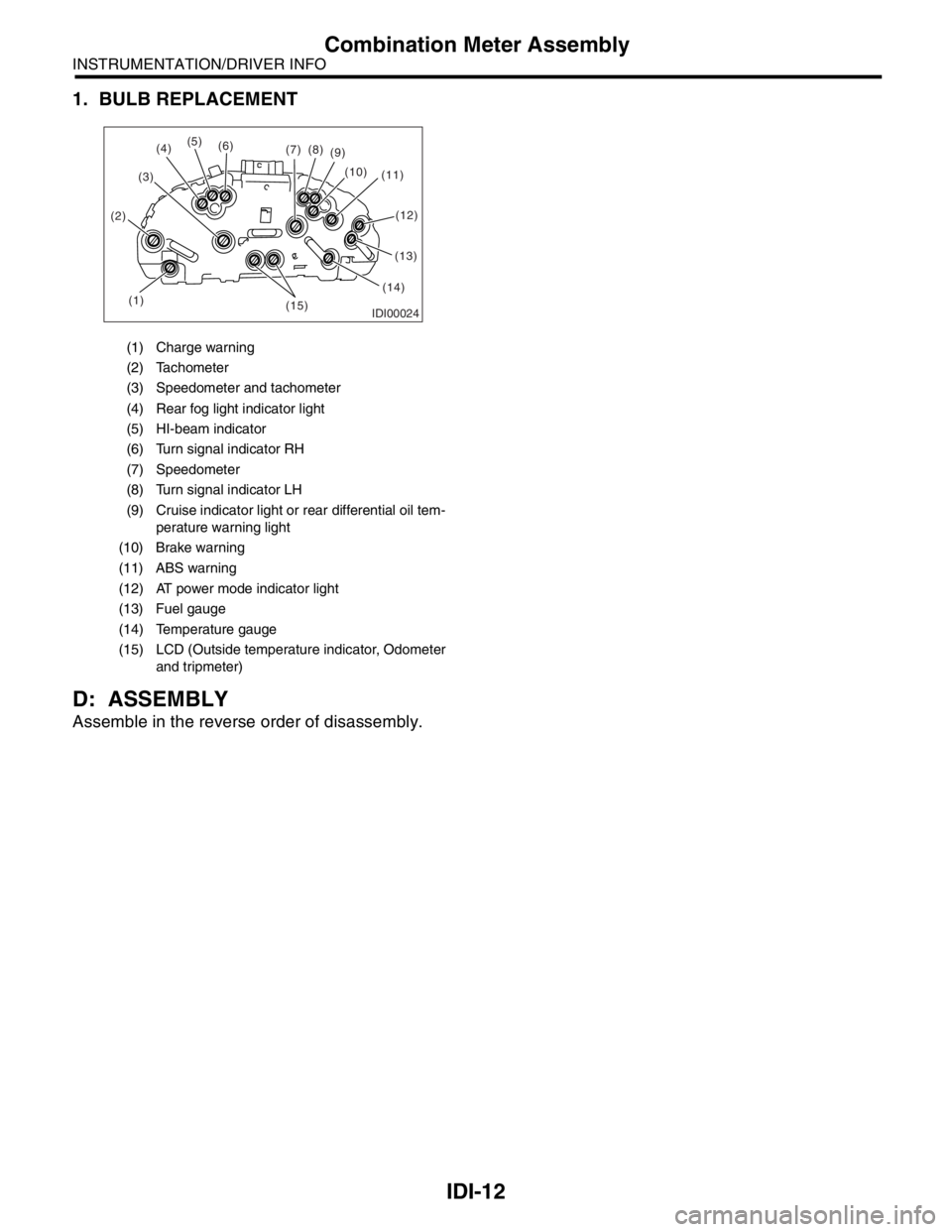
1. BULB REPLACEMENT
D: ASSEMBLY
Assemble in the reverse order of disassembly.
(1) Charge warning
(2) Tachometer
(3) Speedometer and tachometer
(4) Rear fog light indicator light
(5) HI-beam indicator
(6) Turn signal indicator RH
(7) Speedometer
(8) Turn signal indicator LH
(9) Cruise indicator light or rear differential oil tem-
perature warning light
(10) Brake warning
(11) ABS warning
(12) AT power mode indicator light
(13) Fuel gauge
(14) Temperature gauge
(15) LCD (Outside temperature indicator, Odometer
and tripmeter)
IDI00024(1) (2)(3)(5)
(6)
(7)(8)
(9)
(10)
(11)
(13)
(14)
(15)
(4)
(12)
Page 665 of 2870

FUJI HEAVY INDUSTRIES LTD. G8080GE6
2004 FORESTER SERVICE MANUAL QUICK REFERENCE INDEX
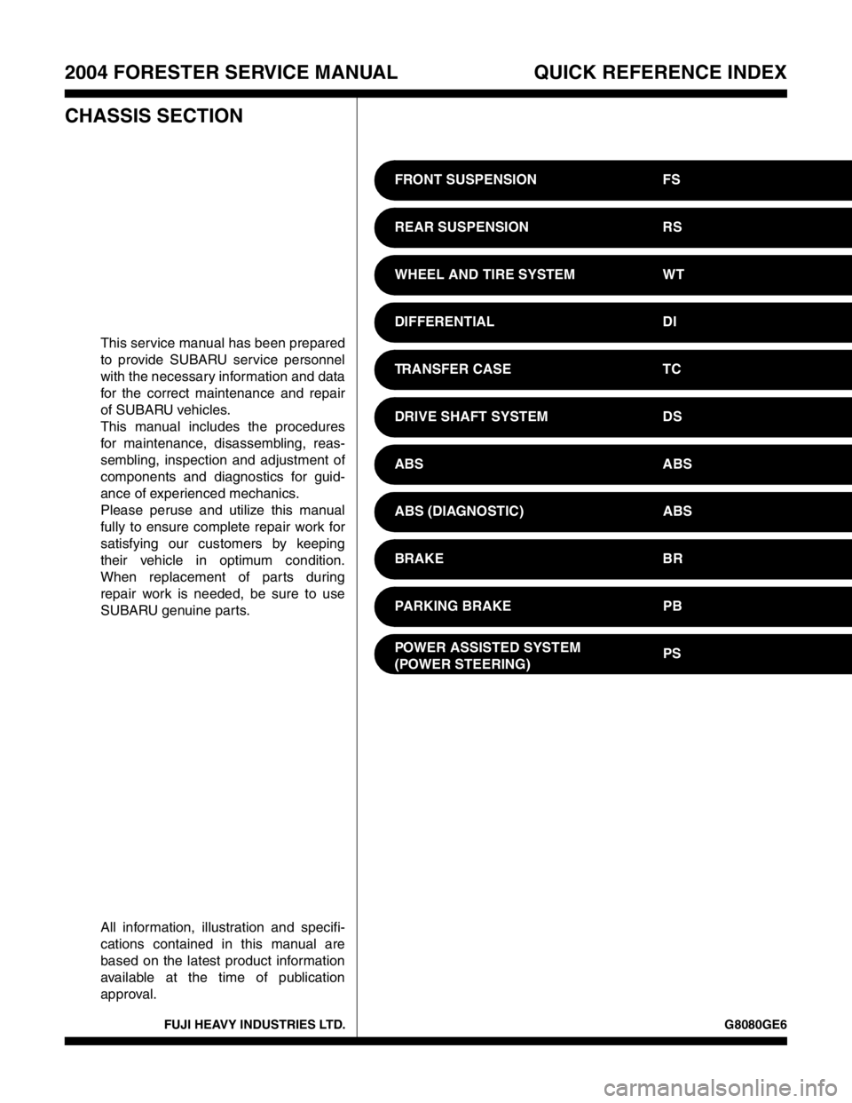
CHASSIS SECTION
This service manual has been prepared
to provide SUBARU service personnel
with the necessary information and data
for the correct maintenance and repair
of SUBARU vehicles.
This manual includes the procedures
for maintenance, disassembling, reas-
sembling, inspection and adjustment of
components and diagnostics for guid-
ance of experienced mechanics.
Please peruse and utilize this manual
fully to ensure complete repair work for
satisfying our customers by keeping
their vehicle in optimum condition.
When replacement of parts during
repair work is needed, be sure to use
SUBARU genuine parts.
All information, illustration and specifi-
cations contained in this manual are
based on the latest product information
available at the time of publication
approval.FRONT SUSPENSION FS
REAR SUSPENSION RS
WHEEL AND TIRE SYSTEM WT
DIFFERENTIAL DI
TRANSFER CASE TC
DRIVE SHAFT SYSTEM DS
ABS ABS
ABS (DIAGNOSTIC) ABS
BRAKE BR
PARKING BRAKE PB
POWER ASSISTED SYSTEM
(POWER STEERING)PS
Page 685 of 2870

HU-2
HOW TO USE THIS MANUAL
How to Use This Manual
1. How to Use This Manual
A: HOW TO USE THIS MANUAL
1. STRUCTURE
Each section consists of SCT that are broken down
into SC that are divided into sections for each com-
ponent. The specification, maintenance and other
information for the components are included, and
diagnosis information has also been added where
necessary.
2. INDEX
The first page has an index with tabs.
Page 701 of 2870

PC-2
PRECAUTION
Precaution
1. Precaution
A: PRECAUTION
Please clearly understand and adhere to the follow-
ing general precautions. They must be strictly fol-
lowed to avoid minor or serious injury to the person
doing the work or people in the area.
1. ABS
Handle the ABS as a total system. Do not disas-
semble or attempt to repair individual parts. Doing
so could prevent the ABS system from operating
when needed or cause it to operate incorrectly and
result in injury.
2. BRAKE FLUID
If brake fluid gets in your eyes or on your skin, do
the following:
Wash out your eyes and seek immediate medical
attention.
Wash your skin with soap and then rinse thor-
oughly with water.
3. RADIATOR FAN
The radiator fan may rotate without warning, even
when the engine is not on. Do not place your hand,
cloth, tools, or other items near the fan at any time.
4. ROAD TESTS
Always conduct road tests in accordance with traf-
fic rules and regulations to avoid bodily injury and
interrupting traffic.
5. AIRBAG
To prevent bodily injury from unexpected deploy-
ment of airbags and unnecessary maintenance, fol-
low the instructions in this manual when performing
maintenance on airbag components or nearby, and
airbag wiring harnesses or nearby.
To prevent unexpected deployment, perform the
steps below and then wait at least 20 seconds to
discharge electricity before beginning work.
Step 1: Turn the ignition switch OFF.
Step 2: Disconnect the ground cable from bat-
tery.
6. AIRBAG DISPOSAL
To prevent bodily injury from unexpected airbag
deployment, do not dispose airbag modules in the
same way as other refuse. Follow all government
regulations concerning disposal of refuse.
7. AIRBAG MODULE
Adhere to the following when handling and storing
the airbag module to prevent bodily injury from un-
expected deployment:
Do not hold the harnesses or connectors to carry
module.
Do not face the bag in the direction that it opens
towards yourself or other people.
Do not face the bag in the direction that it opens
towards the floor or walls.
8. AIRBAG SPECIAL TOOLS
To prevent unexpected deployment, only use spe-
cial tools.
9. WINDOW
Always wear safety glasses when working around
any glass to prevent glass fragments from damag-
ing your eyes.
10.WINDOW ADHESIVE
Always use the recommended or alternative adhe-
sive when attaching glass to prevent it from coming
loose and falling, resulting in accidents and injury.
Page 709 of 2870

NT-8
NOTE
Note
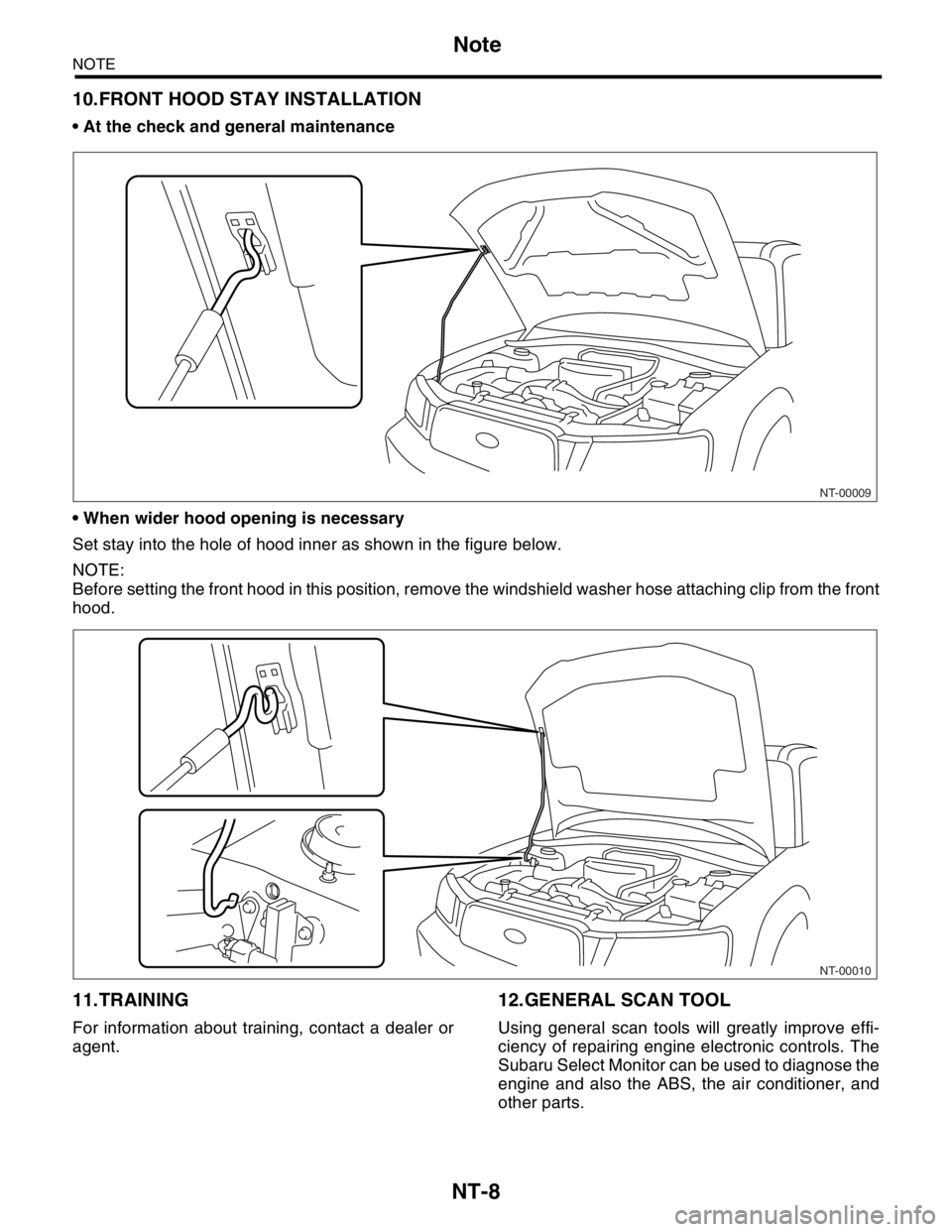
10.FRONT HOOD STAY INSTALLATION
At the check and general maintenance
When wider hood opening is necessary
Set stay into the hole of hood inner as shown in the figure below.
NOTE:
Before setting the front hood in this position, remove the windshield washer hose attaching clip from the front
hood.
11.TRAINING
For information about training, contact a dealer or
agent.
12.GENERAL SCAN TOOL
Using general scan tools will greatly improve effi-
ciency of repairing engine electronic controls. The
Subaru Select Monitor can be used to diagnose the
engine and also the ABS, the air conditioner, and
other parts.
NT-00009
NT-00010