2004 SUBARU FORESTER rear brakes
[x] Cancel search: rear brakesPage 693 of 2870

SPC-4
SPECIFICATION
Forester
F: SUSPENSION
G: BRAKE
★: RHD model
H: TIRE
I: CAPACITY
★1: With oil pump★2: MT model with oil cooler Included★3: Model with ATF warmer Front Macpherson strut type, Independent, Coil spring
Rear Dual-link type, Independent, Coil spring
Model 2.0 L Non-turbo, 2.5 L Non-turbo
2.0 L Turbo, 2.5 L Non-turbo
★, 2.5 L Non-turbo
Service brake system Dual circuit hydraulic with vacuum suspended power unit
Front Ventilated disc brake
Rear Drum brake Disc brake
Parking brake Mechanical on rear brakes
Rim size 15×6J 16×6 1/2J
Tire size 205/70 R15 95H 215/60 R16 95V, P215/60 R16 94H
Type Steel belted radial, Tubeless
Model 2.0 L Non-turbo 2.0 L Turbo 2.5 L Non-turbo 2.5 L Turbo
Tr a n s m i s s i o n 5 M T 4 AT 5 M T 4 AT 5 M T 4 AT 5 M T 4 AT
Fuel tank2 (US gal, Imp gal) 60 (15.9, 13.2)
Engine oil
(When
replacing)2 (US qt, Imp qt) Approx. 4.0 (4.2, 3.5)
Tr a n s m i s -
sion gear oil2 (US qt, Imp qt)4.0
(4.2, 3.5)—3.5
(3.7, 3.1),
3.9
(4.1, 3.4)
★1
—4.0
(4.2, 3.5)—3.5
(3.7, 3.1)—
AT F2 (US qt, Imp qt) —8.4
(8.9, 7.4)—9.3
(9.8, 8.2)—9.3
(9.8, 8.2)—9.3
(9.8, 8.2)
Front differ-
ential gear
oil2 (US qt, Imp qt) —1.2
(1.3, 1.1)—1.2
(1.3, 1.1)—1.2
(1.3, 1.1)—1.2
(1.3, 1.1)
Rear differ-
ential gear
oil2 (US qt, Imp qt) 0.8 (0.8, 0.6)
Pow er
steering
fluid2 (US qt, Imp qt) 0.7 (0.7, 0.6)
Engine
coolant2 (US qt, Imp qt)6.6
(7.0, 5.8)6.5
(6.9, 5.7),
6.9
(7.3, 6.1)
★3
7.4
(7.8, 6.5)7.3
(7.7, 6.4)
★2
6.9
(7.3, 6.1)6.8
(7.2, 6.0)7.4
(7.8, 6.5)7.3
(7.7, 6.4)
Page 769 of 2870

PM-32
PERIODIC MAINTENANCE SERVICE
Brake Fluid
19.Brake Fluid
A: REPLACEMENT
1) Lift-up the vehicle.
2) Remove both front and rear wheels.
3) Draw out the brake fluid from master cylinder
with syringe.
4) Refill the reservoir tank with recommended
brake fluid.
Recommended brake fluid:
FMVSS No. 116, fresh DOT3 or DOT4 brake
fluid
CAUTION:
Avoid mixing different brands of brake fluid
to prevent degrading the quality of the fluid.
Be careful not to allow dirt or dust to get into
the reservoir tank.
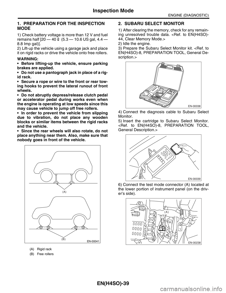
Bleeding sequence (1) → (2) → (3) → (4)
5) Install one end of a vinyl tube onto the air bleeder
and insert the other end of the tube into a container
to collect the brake fluid.
CAUTION:
Cover the bleeder with waste cloth, when
loosening it, to prevent brake fluid from being
splashed over surrounding parts. During the bleeding operation, keep the
brake reservoir tank filled with brake fluid to
eliminate entry of air.
The brake pedal operating must be very slow.
For convenience and safety, two people
should do the work.
NOTE:
The amount of brake fluid required is approx. 500
m2 (16.9 US fl oz, 17.6 Imp fl oz) for total brake
system.
6) Instruct your co-worker to depress the brake
pedal slowly two or three times and then hold it de-
pressed.
7) Loosen the bleeder screw approx. 1/4 turn until a
small amount of brake fluid drains into container,
and then quickly tighten the screw.
8) Repeat steps 6) and 7) above until there are no
air bubbles in the drained brake fluid and new fluid
flows through vinyl tube.
NOTE:
Add brake fluid as necessary while performing the
air bleed operation, in order to prevent the tank
from running short of brake fluid.
9) After completing the bleeding operation, hold
brake pedal depressed and tighten the bleeder
screw and install bleeder cap.
Tightening torque:
8 N·m (0.8 kgf-m, 5.8 ft-lb)
10) Bleed air from each wheel cylinder by following
the previous 5 steps.
11) Depress the brake pedal with a force of approx.
294 N (30 kgf, 66 lb) and hold it there for approx. 20
seconds. At this time check the pedal to see if it
makes any unusual movement. Visually inspect the
bleeder screws and brake pipe joints to make sure
that there is no fluid leakage.
12) Install the wheels, and drive the vehicle for a
short distance between 2 to 3 km (1 to 2 miles) to
make sure that brakes are operating properly.
(1) Front right
(2) Rear left
(3) Front left
(4) Rear right
(5) Secondary
(6) Primary
(1) (4)
(2) (3) (5) (6)
PM-00047
PM-00048
Page 1137 of 2870

EN(H4SO)-39
ENGINE (DIAGNOSTIC)
Inspection Mode
1. PREPARATION FOR THE INSPECTION
MODE
1) Check battery voltage is more than 12 V and fuel
remains half [20 — 402 (5.3 — 10.6 US gal, 4.4 —
8.8 Imp gal)].
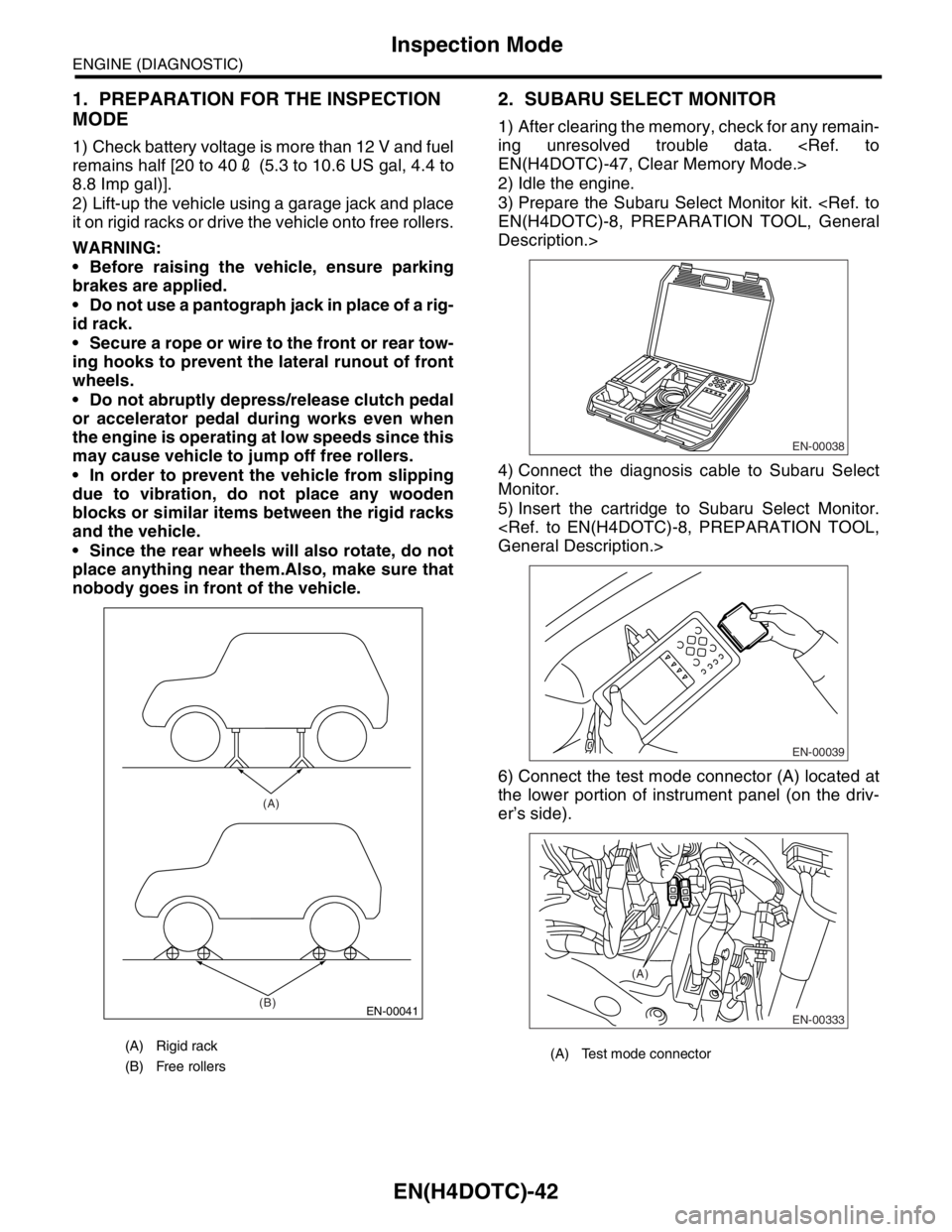
2) Lift-up the vehicle using a garage jack and place
it on rigid racks or drive the vehicle onto free rollers.
WARNING:
Before lifting-up the vehicle, ensure parking
brakes are applied.
Do not use a pantograph jack in place of a rig-
id rack.
Secure a rope or wire to the front or rear tow-
ing hooks to prevent the lateral runout of front
wheels.
Do not abruptly depress/release clutch pedal
or accelerator pedal during works even when
the engine is operating at low speeds since this
may cause vehicle to jump off free rollers.
In order to prevent the vehicle from slipping
due to vibration, do not place any wooden
blocks or similar items between the rigid racks
and the vehicle.
Since the rear wheels will also rotate, do not
place anything near them. Also, make sure that
nobody goes in front of the vehicle.
2. SUBARU SELECT MONITOR
1) After clearing the memory, check for any remain-
ing unresolved trouble data.
2) Idle the engine.
3) Prepare the Subaru Select Monitor kit.
scription.>
4) Connect the diagnosis cable to Subaru Select
Monitor.
5) Insert the cartridge to Subaru Select Monitor.
6) Connect the test mode connector (A) located at
the lower portion of instrument panel (on the driv-
er’s side).
(A) Rigid rack
(B) Free rollers
EN-00041
(A)
(B)
EN-00038
EN-00039
EN-00238
(A)
Page 1672 of 2870

EN(H4DOTC)-42
ENGINE (DIAGNOSTIC)
Inspection Mode
1. PREPARATION FOR THE INSPECTION
MODE
1) Check battery voltage is more than 12 V and fuel
remains half [20 to 402 (5.3 to 10.6 US gal, 4.4 to
8.8 Imp gal)].
2) Lift-up the vehicle using a garage jack and place
it on rigid racks or drive the vehicle onto free rollers.
WARNING:
Before raising the vehicle, ensure parking
brakes are applied.
Do not use a pantograph jack in place of a rig-
id rack.
Secure a rope or wire to the front or rear tow-
ing hooks to prevent the lateral runout of front
wheels.
Do not abruptly depress/release clutch pedal
or accelerator pedal during works even when
the engine is operating at low speeds since this
may cause vehicle to jump off free rollers.
In order to prevent the vehicle from slipping
due to vibration, do not place any wooden
blocks or similar items between the rigid racks
and the vehicle.
Since the rear wheels will also rotate, do not
place anything near them.Also, make sure that
nobody goes in front of the vehicle.
2. SUBARU SELECT MONITOR
1) After clearing the memory, check for any remain-
ing unresolved trouble data.
2) Idle the engine.
3) Prepare the Subaru Select Monitor kit.
Description.>
4) Connect the diagnosis cable to Subaru Select
Monitor.
5) Insert the cartridge to Subaru Select Monitor.
6) Connect the test mode connector (A) located at
the lower portion of instrument panel (on the driv-
er’s side).
(A) Rigid rack
(B) Free rollers
EN-00041
(A)
(B)
(A) Test mode connector
EN-00038
EN-00039
EN-00333
(A)
Page 2061 of 2870

EN(H4DOTC 2.5)-37
ENGINE (DIAGNOSTIC)
Inspection Mode
1. PREPARATION FOR THE INSPECTION
MODE
1) Check battery voltage is more than 12 V and fuel
remains half [20 — 402 (5.3 — 10.6 US gal, 4.4 —
8.8 Imp gal)].
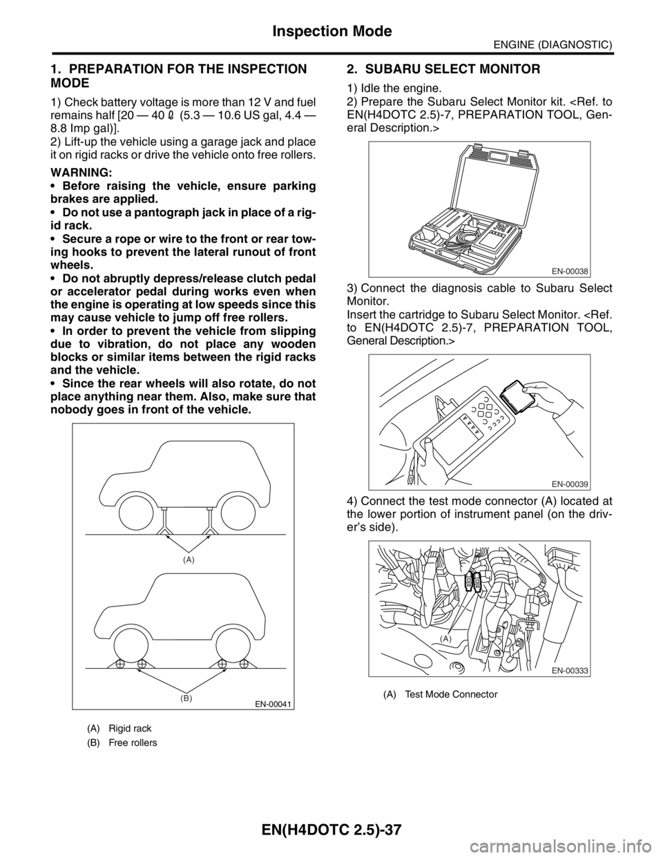
2) Lift-up the vehicle using a garage jack and place
it on rigid racks or drive the vehicle onto free rollers.
WARNING:
Before raising the vehicle, ensure parking
brakes are applied.
Do not use a pantograph jack in place of a rig-
id rack.
Secure a rope or wire to the front or rear tow-
ing hooks to prevent the lateral runout of front
wheels.
Do not abruptly depress/release clutch pedal
or accelerator pedal during works even when
the engine is operating at low speeds since this
may cause vehicle to jump off free rollers.
In order to prevent the vehicle from slipping
due to vibration, do not place any wooden
blocks or similar items between the rigid racks
and the vehicle.
Since the rear wheels will also rotate, do not
place anything near them. Also, make sure that
nobody goes in front of the vehicle.
2. SUBARU SELECT MONITOR
1) Idle the engine.
2) Prepare the Subaru Select Monitor kit.
eral Description.>
3) Connect the diagnosis cable to Subaru Select
Monitor.
Insert the cartridge to Subaru Select Monitor.
General Description.>
4) Connect the test mode connector (A) located at
the lower portion of instrument panel (on the driv-
er’s side).
(A) Rigid rack
(B) Free rollers
EN-00041
(A)
(B)
(A) Test Mode Connector
EN-00038
EN-00039
EN-00333
(A)