Page 593 of 2870
CC(H4SO)-25
CRUISE CONTROL SYSTEM (DIAGNOSTIC)
Diagnostic Procedure with Symptom
H: CHECK INHIBITOR SWITCH (AT MODEL)
TROUBLE SYMPTOM:
Cruise control cannot be set.
WIRING DIAGRAM:
CC-00254
B94T7B12B323
12345678910
11 12 13 14 15 16 17 18 19 20123
4
56
78
9
1011 12
B94
B323
B12
T3
T7
B14
CRUISE
CONTROL
MODULE
INHIBITOR
SWITCH (AT MODEL)STARTER
MOTOR
4
1211
127
WS
WS
WS
OS
OS
123456789101112
:WITHOUT SECURITY SYSTEM
:WITH SECURITY SYSTEM
TO SECURITY
SYSTEM
3412
OS
BATTERY
SBF-1M/B No.2
SECURITY RELAY
2134
Page 594 of 2870

CC(H4SO)-26
CRUISE CONTROL SYSTEM (DIAGNOSTIC)
Diagnostic Procedure with Symptom
Step Check Yes No
1 CHECK INHIBITOR SWITCH CIRCUIT.
1) Turn the ignition switch to OFF.
2) Disconnect the inhibitor switch harness
connector.
3) Turn the ignition switch to ON.
4) Turn the cruise control main switch to ON.
5) Measure the voltage between harness con-
nector terminal and chassis ground.
Connector & terminal
(T7) No. 12 (+) — Chassis ground (
−): Is the voltage more than 10 V? Go to step 2.Check the harness
for open or short
between inhibitor
switch and cruise
control module.
2 CHECK INHIBITOR SWITCH CIRCUIT.
1) Turn the cruise control main switch and
ignition switch to OFF.
2) Disconnect the starter motor harness con-
nector.
3) Measure the resistance between inhibitor
switch harness connector terminal and starter
motor harness connector terminal.
Connector & terminal
(T7) No. 7 — (B14) No. 1: Is the resistance less than 10
Ω?Go to step 3.Repair the har-
ness.
3 CHECK INHIBITOR SWITCH.
Remove and check the inhibitor switch.
to CC-12, Inhibitor Switch (AT model).>Is the inhibitor switch OK? Inhibitor switch cir-
cuit is OK.Replace the inhibi-
tor switch.
Page 634 of 2870
CC(H4DOTC 2.5)-22
CRUISE CONTROL SYSTEM (DIAGNOSTIC)
Diagnostic Procedure with Diagnostic Trouble Code (DTC)
D: DTC 14 NEUTRAL POSITION SWITCH
TROUBLE SYMPTOM:
Cruise control cannot be set.
WIRING DIAGRAM:
CC-00258
B137
D9
B128
T9
T9
B128
1
B21
E216
3
E
B128F2B137
9
30
29 283120 19 18
22
211012
1114
24
27 26
17 16123456713
2315
258 B21123
4
56
78
9
1011 12
1314 15 16
34121234 5678910 11 12 13 14 15 16 17 18 19 20
GE-2
AT
T77 12
B12
T3
AT
:AT MODEL MT
:MT MODEL
1112
B14
MT
123456789101112
T7B12
ECM
NEUTRAL
POSITION
SWITCH
INHIBITOR
SWITCH
(
AT MODEL)STARTER
MOTOR
Page 894 of 2870

ME(H4SO)-25
MECHANICAL
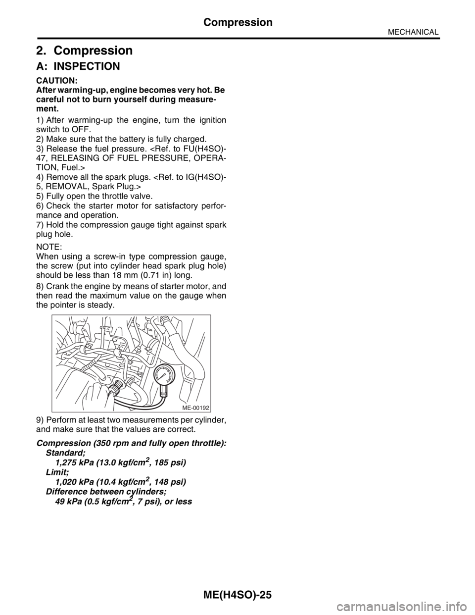
Compression
2. Compression
A: INSPECTION
CAUTION:
After warming-up, engine becomes very hot. Be
careful not to burn yourself during measure-
ment.
1) After warming-up the engine, turn the ignition
switch to OFF.
2) Make sure that the battery is fully charged.
3) Release the fuel pressure.
47, RELEASING OF FUEL PRESSURE, OPERA-
TION, Fuel.>
4) Remove all the spark plugs.
5, REMOVAL, Spark Plug.>
5) Fully open the throttle valve.
6) Check the starter motor for satisfactory perfor-
mance and operation.
7) Hold the compression gauge tight against spark
plug hole.
NOTE:
When using a screw-in type compression gauge,
the screw (put into cylinder head spark plug hole)
should be less than 18 mm (0.71 in) long.
8) Crank the engine by means of starter motor, and
then read the maximum value on the gauge when
the pointer is steady.
9) Perform at least two measurements per cylinder,
and make sure that the values are correct.
Compression (350 rpm and fully open throttle):
Standard;
1,275 kPa (13.0 kgf/cm
2, 185 psi)
Limit;
1,020 kPa (10.4 kgf/cm
2, 148 psi)
Difference between cylinders;
49 kPa (0.5 kgf/cm
2, 7 psi), or less
ME-00192
Page 906 of 2870

ME(H4SO)-37
MECHANICAL
Engine Assembly
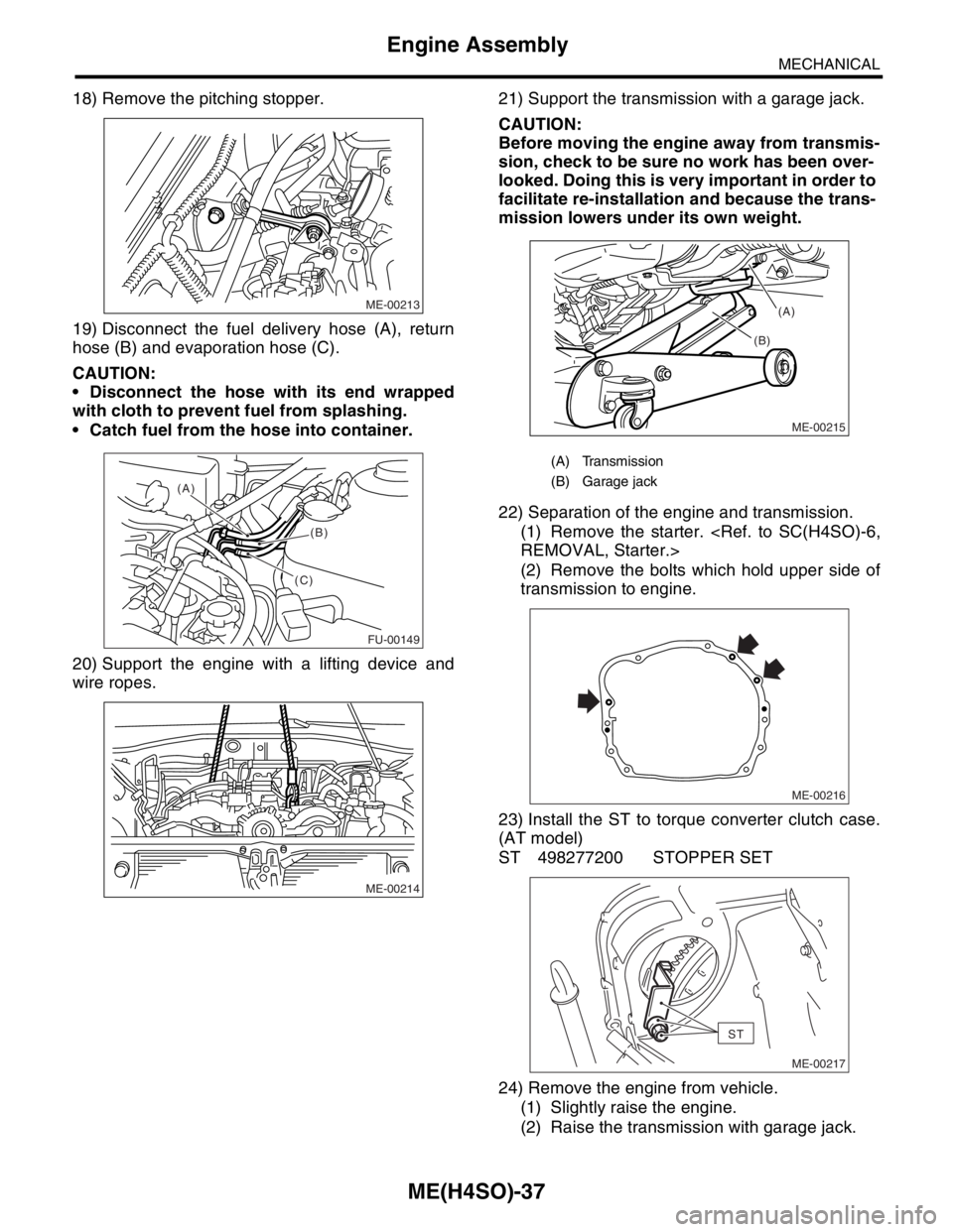
18) Remove the pitching stopper.
19) Disconnect the fuel delivery hose (A), return
hose (B) and evaporation hose (C).
CAUTION:
Disconnect the hose with its end wrapped
with cloth to prevent fuel from splashing.
Catch fuel from the hose into container.
20) Support the engine with a lifting device and
wire ropes.21) Support the transmission with a garage jack.
CAUTION:
Before moving the engine away from transmis-
sion, check to be sure no work has been over-
looked. Doing this is very important in order to
facilitate re-installation and because the trans-
mission lowers under its own weight.
22) Separation of the engine and transmission.
(1) Remove the starter.
REMOVAL, Starter.>
(2) Remove the bolts which hold upper side of
transmission to engine.
23) Install the ST to torque converter clutch case.
(AT model)
ST 498277200 STOPPER SET
24) Remove the engine from vehicle.
(1) Slightly raise the engine.
(2) Raise the transmission with garage jack.
ME-00213
FU-00149
(A)
(B)
(C)
ME-00214
(A) Transmission
(B) Garage jack
ME-00215
(B)(A)
ME-00216
ST
ME-00217
Page 907 of 2870

ME(H4SO)-38
MECHANICAL
Engine Assembly
(3) Move the engine horizontally until main
shaft is withdrawn from clutch cover.
(4) Slowly move the engine away from engine
compartment.
NOTE:
Be careful not to damage the adjacent parts or
body panels with crank pulley, oil level gauge, etc.
25) Remove the front cushion rubbers.
B: INSTALLATION
1) Install the front cushion rubbers.
Tightening torque:
34 N
⋅m (3.5 kgf-m, 25.3 ft-lb)
2) Install the engine onto transmission.
(1) Position the engine in engine compartment
and align it with transmission.
NOTE:
Be careful not to damage the adjacent parts or
body panels with crank pulley, oil level gauge, etc.
(2) Apply a small amount of grease to the spline
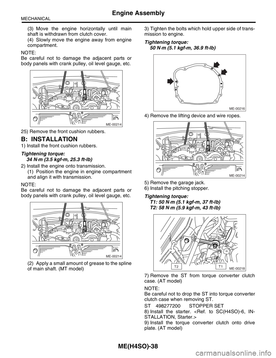
of main shaft. (MT model)3) Tighten the bolts which hold upper side of trans-
mission to engine.
Tightening torque:
50 N
⋅m (5.1 kgf-m, 36.9 ft-lb)
4) Remove the lifting device and wire ropes.
5) Remove the garage jack.
6) Install the pitching stopper.
Tightening torque:
T1: 50 N
⋅m (5.1 kgf-m, 37 ft-lb)
T2: 58 N
⋅m (5.9 kgf-m, 43 ft-lb)
7) Remove the ST from torque converter clutch
case. (AT model)
NOTE:
Be careful not to drop the ST into torque converter
clutch case when removing ST.
ST 498277200 STOPPER SET
8) Install the starter.
STALLATION, Starter.>
9) Install the torque converter clutch onto drive
plate. (AT model)
ME-00214
ME-00214
ME-00216
ME-00214
ME-00218T2T1
Page 962 of 2870

ME(H4SO)-91
MECHANICAL
Engine Trouble in General
22.Engine Trouble in General
A: INSPECTION
NOTE:
“RANK” shown in the chart refer to the possibility of reason for the trouble in order (“Very often” to “Rarely”)
A — Very often
B — Sometimes
C — Rarely
TROUBLE PROBLEM PARTS, ETC. POSSIBLE CAUSE RANK
1. Engine will not start.
1) Starter does not turn. Starter Defective battery-to-starter harness B
Defective starter switch C
Defective inhibitor switch or neutral switch C
Defective starter B
Battery Poor terminal connection A
Run-down battery A
Defective charging system B
Friction Seizure of crankshaft and connecting rod bearing C
Seized camshaft C
Seized or stuck piston and cylinder C
2) Initial combustion does
not occur. Starter Defective starter C
Engine control system A
Fuel line Defective fuel pump and relay A
Lack of or insufficient fuel B
Belt Defective B
Defective timing B
Compression Incorrect valve clearance C
Loosened spark plugs or defective gasket C
Loosened cylinder head bolts or defective gasket C
Improper valve seating C
Defective valve stem C
Worn or broken valve spring B
Worn or stuck piston rings, cylinder and piston C
Incorrect valve timing B
Improper engine oil (low viscosity) B
3) Initial combustion occurs. Engine control system A
Intake system Defective intake manifold gasket B
Defective throttle body gasket B
Fuel line Defective fuel pump and relay C
Clogged fuel line C
Lack of or insufficient fuel B
Belt Defective B
Defective timing B
Compression Incorrect valve clearance C
Loosened spark plugs or defective gasket C
Loosened cylinder head bolts or defective gasket C
Improper valve seating C
Defective valve stem C
Worn or broken valve spring B
Worn or stuck piston rings, cylinder and piston C
Incorrect valve timing B
Improper engine oil (low viscosity) B
Page 967 of 2870

ME(H4SO)-96
MECHANICAL
Engine Noise
23.Engine Noise
A: INSPECTION
NOTE*:
When disconnecting fuel injector connector, the malfunction indicator light illuminates and DTC is stored in ECM memory.
Therefore, carry out the clear memory mode and inspection mode
after connecting fuel injector connector.Type of sound Condition Possible cause
Regular clicking soundSound increases as engine
speed increases. Valve mechanism is defective.
Incorrect valve clearance
Worn valve rocker
Worn camshaft
Broken valve spring
Heavy and dull clankOil pressure is low. Worn crankshaft main bearing
Worn connecting rod bearing (big end)
Oil pressure is normal. Loose flywheel mounting bolts
Damaged engine mounting
High-pitched clank (Spark
knock)Sound is noticeable when
accelerating with an overload. Ignition timing advanced
Accumulation of carbon inside combustion chamber
Wrong spark plug
Improper gasoline
Clank when engine speed is
medium (1,000 to 2,000 rpm).Sound is reduced when fuel
injector connector of noisy cyl-
inder is disconnected.
(NOTE*) Worn crankshaft main bearing
Worn bearing at crankshaft end of connecting rod
Knocking sound when engine
is operating under idling speed
and engine is warmSound is reduced when fuel
injector connector of noisy cyl-
inder is disconnected.
(NOTE*) Worn cylinder liner and piston ring
Broken or stuck piston ring
Worn piston pin and hole at piston end of connecting rod
Sound is not reduced if each
fuel injector connector is dis-
connected in turn. (NOTE*) Unusually worn valve lifter
Worn cam gear
Worn camshaft journal bore in crankcase
Squeaky sound — Insufficient generator lubrication
Rubbing sound — Defective generator brush and rotor contact
Gear scream when starting
engine— Defective ignition starter switch
Worn gear and starter pinion
Sound like polishing glass with
a dry cloth— Loose drive belt
Defective water pump shaft
Hissing sound — Loss of compression
Air leakage in air intake system, hoses, connections or mani-
folds
Timing belt noise — Loose timing belt
Belt contacting case/adjacent part
Valve tappet noise — Incorrect valve clearance