2004 SUBARU FORESTER camshaft
[x] Cancel search: camshaftPage 691 of 2870
SPC-2
SPECIFICATION
Forester
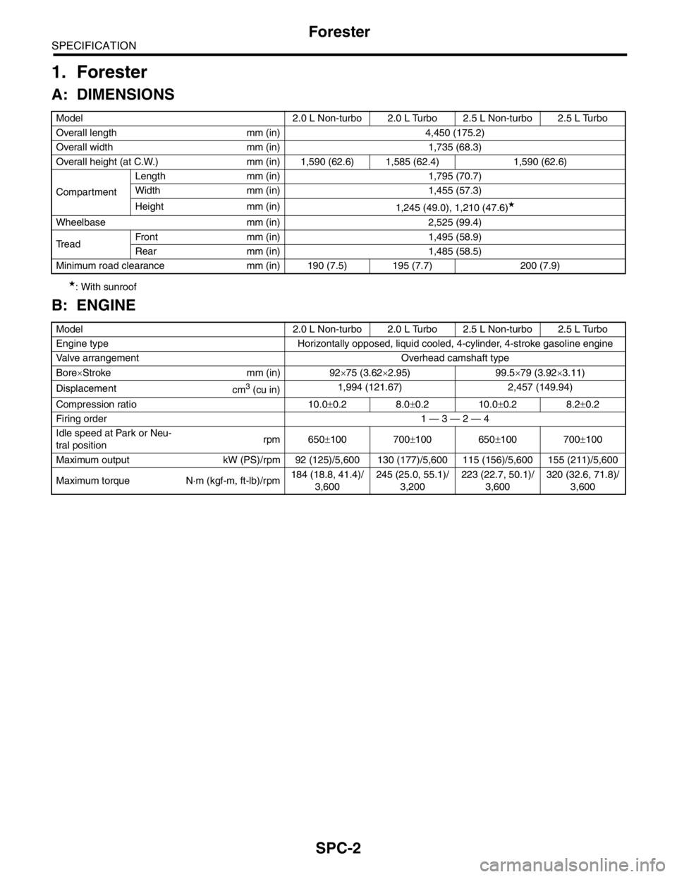
1. Forester
A: DIMENSIONS
★: With sunroof
B: ENGINE
Model 2.0 L Non-turbo 2.0 L Turbo 2.5 L Non-turbo 2.5 L Turbo
Overall length mm (in) 4,450 (175.2)
Overall width mm (in) 1,735 (68.3)
Overall height (at C.W.) mm (in) 1,590 (62.6) 1,585 (62.4) 1,590 (62.6)
CompartmentLength mm (in) 1,795 (70.7)
Width mm (in) 1,455 (57.3)
Height mm (in)
1,245 (49.0), 1,210 (47.6)
★
Wheelbase mm (in) 2,525 (99.4)
Tread Front mm (in) 1,495 (58.9)
Rear mm (in) 1,485 (58.5)
Minimum road clearance mm (in) 190 (7.5) 195 (7.7) 200 (7.9)
Model 2.0 L Non-turbo 2.0 L Turbo 2.5 L Non-turbo 2.5 L Turbo
Engine type Horizontally opposed, liquid cooled, 4-cylinder, 4-stroke gasoline engine
Valve arrangement Overhead camshaft type
Bore×Stroke mm (in) 92×75 (3.62×2.95) 99.5×79 (3.92×3.11)
Displacement
cm
3 (cu in)1,994 (121.67) 2,457 (149.94)
Compression ratio 10.0±0.2 8.0±0.2 10.0±0.2 8.2±0.2
Firing order 1 — 3 — 2 — 4
Idle speed at Park or Neu-
tral positionrpm 650±100 700±100 650±100 700±100
Maximum output kW (PS)/rpm 92 (125)/5,600 130 (177)/5,600 115 (156)/5,600 155 (211)/5,600
Maximum torque N⋅m (kgf-m, ft-lb)/rpm184 (18.8, 41.4)/
3,600245 (25.0, 55.1)/
3,200223 (22.7, 50.1)/
3,600320 (32.6, 71.8)/
3,600
Page 722 of 2870
RM-7
RECOMMENDED MATERIAL
Recommended Materials
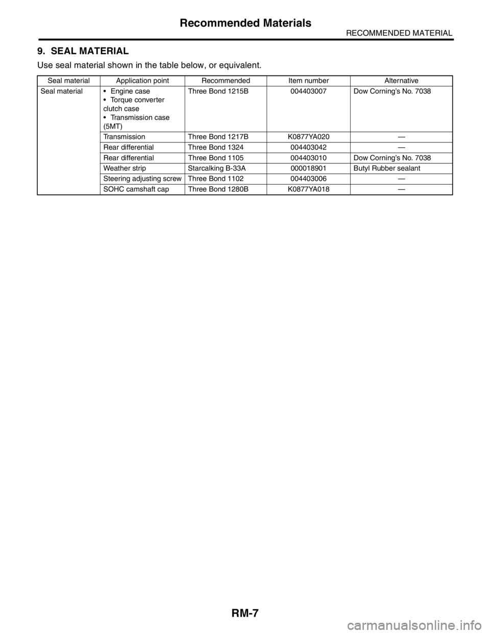
9. SEAL MATERIAL
Use seal material shown in the table below, or equivalent.
Seal material Application point Recommended Item number Alternative
Seal material Engine case
Torque converter
clutch case
Transmission case
(5MT)Three Bond 1215B 004403007 Dow Corning’s No. 7038
Transmission Three Bond 1217B K0877YA020 —
Rear differential Three Bond 1324 004403042 —
Rear differential Three Bond 1105 004403010 Dow Corning’s No. 7038
Weather strip Starcalking B-33A 000018901 Butyl Rubber sealant
Steering adjusting screw Three Bond 1102 004403006 —
SOHC camshaft cap Three Bond 1280B K0877YA018 —
Page 740 of 2870
PM-3
PERIODIC MAINTENANCE SERVICE
Schedule
2. Schedule
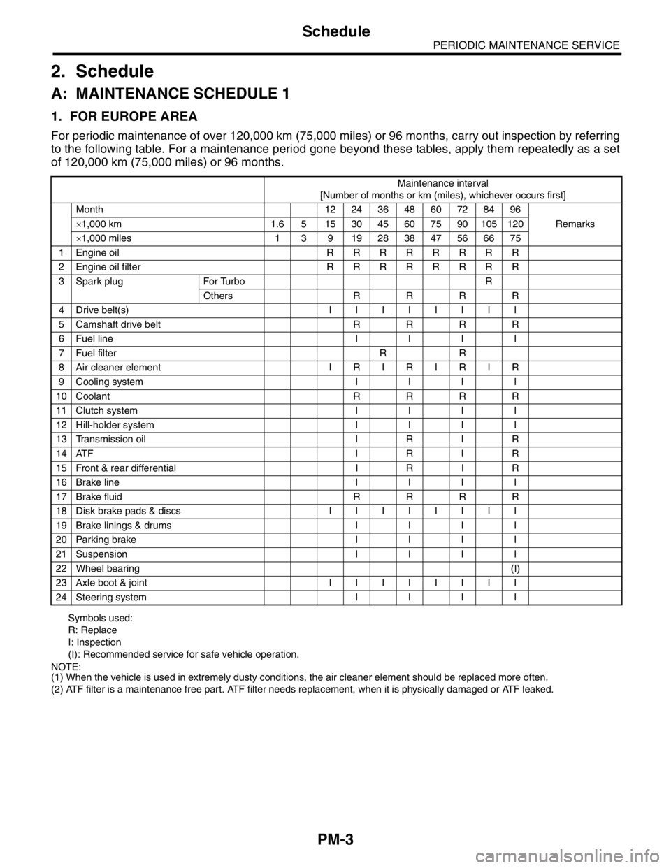
A: MAINTENANCE SCHEDULE 1
1. FOR EUROPE AREA
For periodic maintenance of over 120,000 km (75,000 miles) or 96 months, carry out inspection by referring
to the following table. For a maintenance period gone beyond these tables, apply them repeatedly as a set
of 120,000 km (75,000 miles) or 96 months.
Symbols used:
R: Replace
I: Inspection
(I): Recommended service for safe vehicle operation.
N
OTE:
(1) When the vehicle is used in extremely dusty conditions, the air cleaner element should be replaced more often.
(2) ATF filter is a maintenance free part. ATF filter needs replacement, when it is physically damaged or ATF leaked.Maintenance interval
[Number of months or km (miles), whichever occurs first]
Month 1224364860728496
Remarks ×1,000 km 1.6 5 15 30 45 60 75 90 105 120
×1,000 miles 1 3 9 19 28 38 47 56 66 75
1Engine oil RRRRRRRR
2Engine oil filter RRRRRRRR
3 Spark plug For Turbo R
Others RRRR
4Drive belt(s) IIIIIIII
5Camshaft drive belt RRRR
6Fuel line IIII
7 Fuel filter R R
8 Air cleaner element I R I R I R I R
9Cooling system IIII
10Coolant RRRR
11Clutch system IIII
12Hill-holder system IIII
13 Transmission oil I R I R
14 ATF I R I R
15 Front & rear differential I R I R
16Brake line IIII
17Brake fluid RRRR
18Disk brake pads & discs IIIIIIII
19Brake linings & drums IIII
20Parking brake IIII
21Suspension IIII
22 Wheel bearing(I)
23Axle boot & joint IIIIIIII
24Steering system IIII
Page 741 of 2870
PM-4
PERIODIC MAINTENANCE SERVICE
Schedule
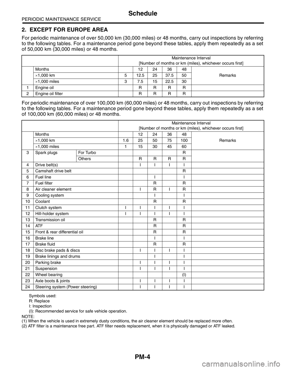
2. EXCEPT FOR EUROPE AREA
For periodic maintenance of over 50,000 km (30,000 miles) or 48 months, carry out inspections by referring
to the following tables. For a maintenance period gone beyond these tables, apply them repeatedly as a set
of 50,000 km (30,000 miles) or 48 months.
For periodic maintenance of over 100,000 km (60,000 miles) or 48 months, carry out inspections by referring
to the following tables. For a maintenance period gone beyond these tables, apply them repeatedly as a set
of 100,000 km (60,000 miles) or 48 months.
Symbols used:
R: Replace
I: Inspection
(I): Recommended service for safe vehicle operation.
N
OTE:
(1) When the vehicle is used in extremely dusty conditions, the air cleaner element should be replaced more often.
(2) ATF filter is a maintenance free part. ATF filter needs replacement, when it is physically damaged or ATF leaked.Maintenance Interval
[Number of months or km (miles), whichever occurs first]
Months 12 24 36 48
Remarks ×1,000 km 5 12.5 25 37.5 50
×1,000 miles 3 7.5 15 22.5 30
1 Engine oil R R R R
2 Engine oil filter R R R R
Maintenance Interval
[Number of months or km (miles), whichever occurs first]
Months 12 24 36 48
Remarks ×1,000 km 1.6 25 50 75 100
×1,000 miles 1 15 30 45 60
3 Spark plugs For Turbo R
Others R R R R
4Drive belt(s) IIII
5 Camshaft drive belt R
6 Fuel line I I
7 Fuel filter R R
8 Air cleaner element I R I R
9 Cooling system I I
10 Coolant R R
11 Clutch system I I I I I
12 Hill-holder system I I I I I
13 Transmission oil R R
14 ATF R R
15 Front & rear differential oil R R
16 Brake line I I
17 Brake fluid R R
18 Disc brake pads & discs I I I I
19 Brake linings and drums I I
20 Parking brake I I I I
21 Suspension I I I I
22 Wheel bearing (I)
23 Axle boots & joints I I I I
24 Steering system (Power steering) I I I I
Page 783 of 2870
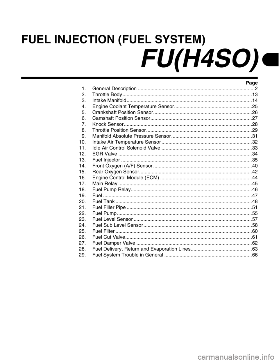
FUEL INJECTION (FUEL SYSTEM)
FU(H4SO)
Page
1. General Description ....................................................................................2
2. Throttle Body .............................................................................................13
3. Intake Manifold ..........................................................................................14
4. Engine Coolant Temperature Sensor........................................................25
5. Crankshaft Position Sensor.......................................................................26
6. Camshaft Position Sensor.........................................................................27
7. Knock Sensor ............................................................................................28
8. Throttle Position Sensor ............................................................................29
9. Manifold Absolute Pressure Sensor ..........................................................31
10. Intake Air Temperature Sensor .................................................................32
11. Idle Air Control Solenoid Valve .................................................................33
12. EGR Valve ................................................................................................34
13. Fuel Injector ..............................................................................................35
14. Front Oxygen (A/F) Sensor .......................................................................40
15. Rear Oxygen Sensor.................................................................................42
16. Engine Control Module (ECM) ..................................................................44
17. Main Relay ................................................................................................45
18. Fuel Pump Relay.......................................................................................46
19. Fuel ...........................................................................................................47
20. Fuel Tank ..................................................................................................48
21. Fuel Filler Pipe ..........................................................................................51
22. Fuel Pump .................................................................................................55
23. Fuel Level Sensor .....................................................................................57
24. Fuel Sub Level Sensor ..............................................................................58
25. Fuel Filter ..................................................................................................60
26. Fuel Cut Valve...........................................................................................61
27. Fuel Damper Valve ...................................................................................62
28. Fuel Delivery, Return and Evaporation Lines............................................63
29. Fuel System Trouble in General ...............................................................66
Page 788 of 2870
FU(H4SO)-6
FUEL INJECTION (FUEL SYSTEM)
General Description
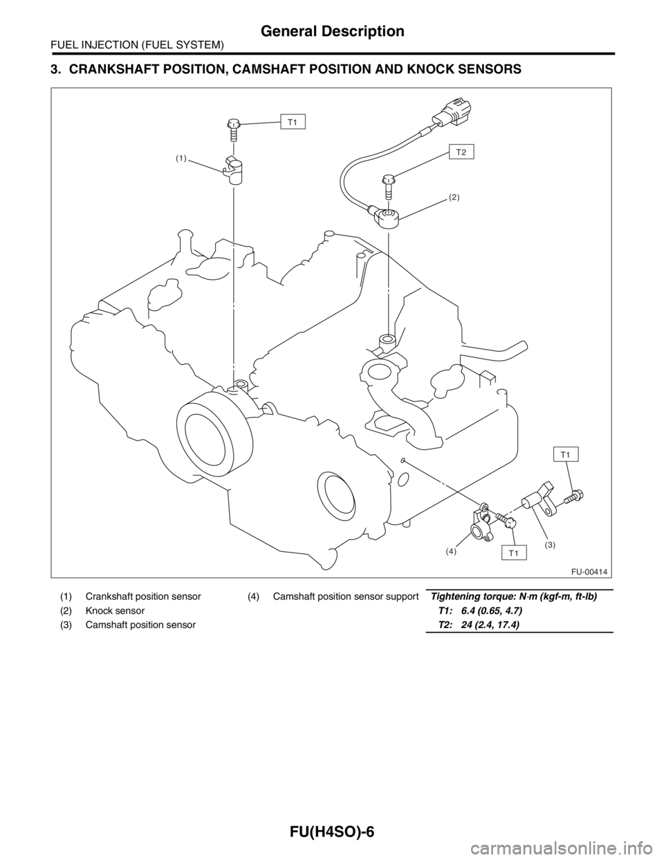
3. CRANKSHAFT POSITION, CAMSHAFT POSITION AND KNOCK SENSORS
(1) Crankshaft position sensor (4) Camshaft position sensor supportTightening torque: N⋅m (kgf-m, ft-lb)
(2) Knock sensorT1: 6.4 (0.65, 4.7)
(3) Camshaft position sensorT2: 24 (2.4, 17.4)
FU-00414
T1
(1)
(2)
T1
T1(3)
(4)
T2
Page 798 of 2870
FU(H4SO)-16
FUEL INJECTION (FUEL SYSTEM)
Intake Manifold
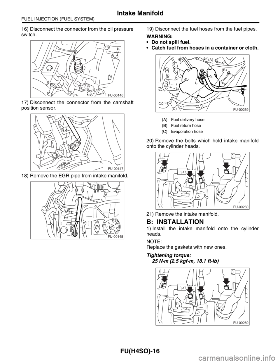
16) Disconnect the connector from the oil pressure
switch.
17) Disconnect the connector from the camshaft
position sensor.
18) Remove the EGR pipe from intake manifold.19) Disconnect the fuel hoses from the fuel pipes.
WARNING:
Do not spill fuel.
Catch fuel from hoses in a container or cloth.
20) Remove the bolts which hold intake manifold
onto the cylinder heads.
21) Remove the intake manifold.
B: INSTALLATION
1) Install the intake manifold onto the cylinder
heads.
NOTE:
Replace the gaskets with new ones.
Tightening torque:
25 N
⋅m (2.5 kgf-m, 18.1 ft-lb)
FU-00146
FU-00147
FU-00148
(A) Fuel delivery hose
(B) Fuel return hose
(C) Evaporation hose
(B) (A)
(C)
FU-00259
FU-00260
FU-00260
Page 799 of 2870
FU(H4SO)-17
FUEL INJECTION (FUEL SYSTEM)
Intake Manifold
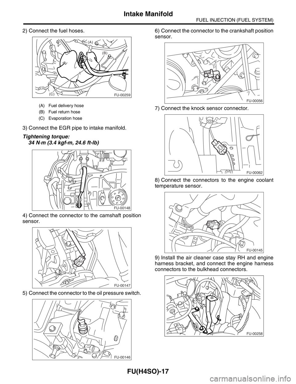
2) Connect the fuel hoses.
3) Connect the EGR pipe to intake manifold.
Tightening torque:
34 N
⋅m (3.4 kgf-m, 24.6 ft-lb)
4) Connect the connector to the camshaft position
sensor.
5) Connect the connector to the oil pressure switch.6) Connect the connector to the crankshaft position
sensor.
7) Connect the knock sensor connector.
8) Connect the connectors to the engine coolant
temperature sensor.
9) Install the air cleaner case stay RH and engine
harness bracket, and connect the engine harness
connectors to the bulkhead connectors.
(A) Fuel delivery hose
(B) Fuel return hose
(C) Evaporation hose
(B) (A)
(C)
FU-00259
FU-00148
FU-00147
FU-00146
FU-00056
FU-00062
FU-00145
FU-00258