2004 SUBARU FORESTER fuel pressure
[x] Cancel search: fuel pressurePage 268 of 2870

LI-14
LIGHTING SYSTEM
Headlight Assembly
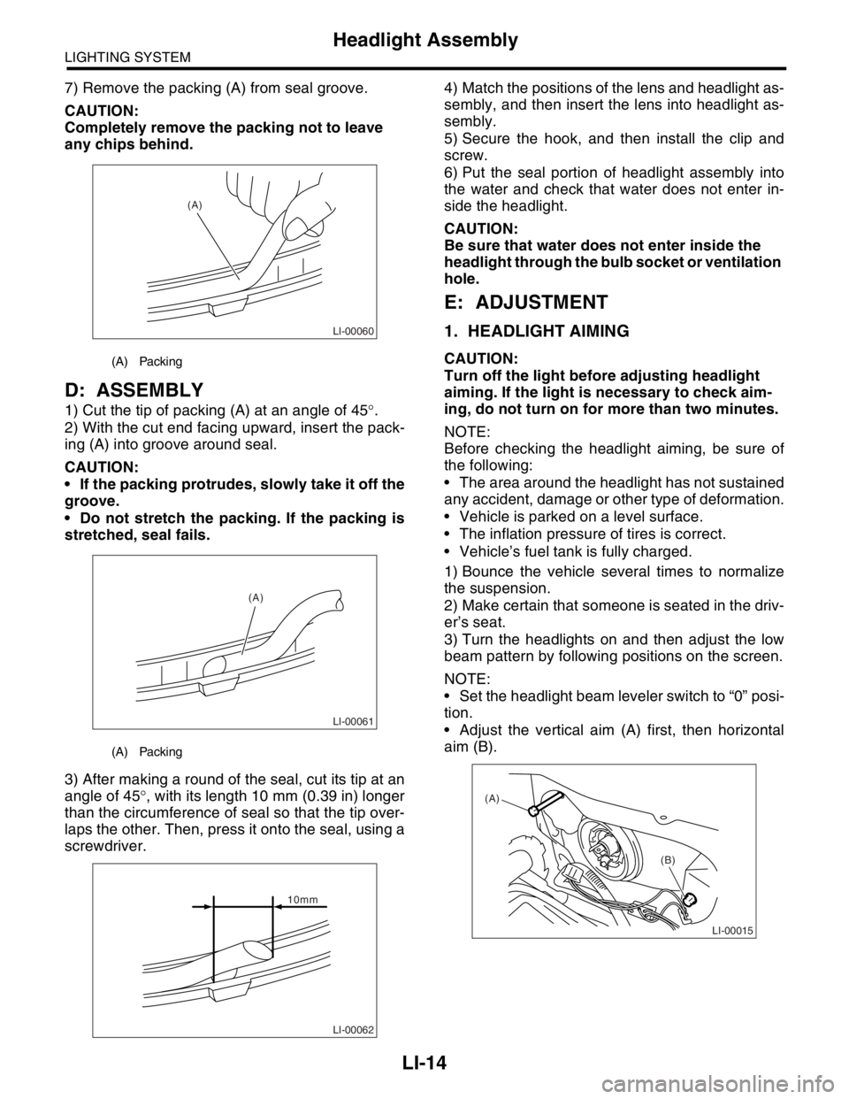
7) Remove the packing (A) from seal groove.
CAUTION:
Completely remove the packing not to leave
any chips behind.
D: ASSEMBLY
1) Cut the tip of packing (A) at an angle of 45°.
2) With the cut end facing upward, insert the pack-
ing (A) into groove around seal.
CAUTION:
If the packing protrudes, slowly take it off the
groove.
Do not stretch the packing. If the packing is
stretched, seal fails.
3) After making a round of the seal, cut its tip at an
angle of 45°, with its length 10 mm (0.39 in) longer
than the circumference of seal so that the tip over-
laps the other. Then, press it onto the seal, using a
screwdriver.4) Match the positions of the lens and headlight as-
sembly, and then insert the lens into headlight as-
sembly.
5) Secure the hook, and then install the clip and
screw.
6) Put the seal portion of headlight assembly into
the water and check that water does not enter in-
side the headlight.
CAUTION:
Be sure that water does not enter inside the
headlight through the bulb socket or ventilation
hole.
E: ADJUSTMENT
1. HEADLIGHT AIMING
CAUTION:
Turn off the light before adjusting headlight
aiming. If the light is necessary to check aim-
ing, do not turn on for more than two minutes.
NOTE:
Before checking the headlight aiming, be sure of
the following:
The area around the headlight has not sustained
any accident, damage or other type of deformation.
Vehicle is parked on a level surface.
The inflation pressure of tires is correct.
Vehicle’s fuel tank is fully charged.
1) Bounce the vehicle several times to normalize
the suspension.
2) Make certain that someone is seated in the driv-
er’s seat.
3) Turn the headlights on and then adjust the low
beam pattern by following positions on the screen.
NOTE:
Set the headlight beam leveler switch to “0” posi-
tion.
Adjust the vertical aim (A) first, then horizontal
aim (B).(A) Packing
(A) Packing
LI-00060
(A)
LI-00061
(A)
LI-00062
10mm
LI-00015
(A)
(B)
Page 386 of 2870

IDI-2
INSTRUMENTATION/DRIVER INFO
General Description
1. General Description
A: SPECIFICATION
B: CAUTION
Be careful not to damage meters and instrument panel.
Be careful not to damage meter glasses.
Make sure that electrical connector is connected securely.
After installation, make sure that each meter operates normally.
Use gloves to avoid damage and getting fingerprints on the glass surface and meter surfaces.
Do not apply excessive force to the printed circuit.
Do not drop or otherwise apply impact.
C: PREPARATION TOOL
1. GENERAL TOOL
Combination meterSpeedometer Electric pulse type
Temperature gauge Cross coil type
Fuel gauge Cross coil type
Tachometer Electric pulse type
Turn signal indicator light 14 V — 2 W
Charge indicator light 14 V — 1.4 W
Oil pressure indicator light LED
ABS warning light 14 V — 1.4 W
Malfunction indicator light LED
HI-beam indicator light 14 V — 2 W
Door open warning light LED
Seat belt warning light LED
Brake fluid and parking brake warning
light14 V — 2 W
FWD indicator light LED
AIRBAG warning light LED
Meter illumination light 14 V — 3.4 W, 14 V — 2 W
AT OIL TEMP. warning light LED
LO indicator light LED
HOLD indicator light LED
Immobilizer indicator light LED
Rear differential oil temperature warn-
ing light14 V — 2 W
Cruise indicator light 14 V — 1.4 W
Rear fog light indicator light 14 V — 2 W
POWER indicator light 14 V — 1.4 W
Low fuel warning light LED
AT select lever position indicator light 14 V — 100 mA
LCD back light 14 V — 1.4 W
TOOL NAME REMARKS
Circuit tester Used for measuring resistance and voltage.
Page 726 of 2870

PI-3
PRE-DELIVERY INSPECTION
Pre-delivery Inspection
B: PDI PROCEDURE
Follow the procedures shown in the table below.
Static Checks Just After Vehicle Receipt
Step Check point
1. Appearance check (1) If the vehicle is covered with protective coating, visually check the vehicle
body for damage and dents. If the protective coating has been removed,
visually check the body paints for small areas of damage or stains.
(2) Visually check the glass and light lenses for any damage and cracks or
excessive gaps to the body sheet metal.
(3) Visually check the plated parts for any damage.
2. Tire check (1) Check the tires for damage, abnormal conditions, and dents on the
wheels.
(2) Check the tire air pressure.
3. Fuse installation If the vehicle is about to be delivered to the customer, attach a room light
fuse.
4. Connection of air conditioner harness If the vehicle is about to be delivered to the customer, connect the air condi-
tioner harness.
5. Check the doors for lock/unlock and open/close
operations.(1) Using the key, check if the door can be locked and unlocked normally.
(2) Open and close all doors to see that there are no abnormal conditions.
6. Operation check of double lock Check that the double lock operates normally.
7. Operation check of the child safety lock system. Check the child safety lock system operates normally.
8. Check the rear gate for lock/unlock and open/
close operations.(1) Check if the rear gate can be unlocked normally from the emergency
door.
(2) Open and close the rear gate to see that there are no abnormal condi-
tions.
(3) Operate the power door locking switch to check that the rear gate is
locked and unlocked normally.
9. Operation check of fuel lid opener lock release
leverOperate the fuel lid opener to check that the fuel lid is unlocked normally.
10. Accessory check Check that the following accessories are provided:
Owner’s manual
Warranty booklet
Service booklet
Spare key
Jack
Tool set
Spare tire
11. Operation check of hood lock release system Operate the hood lock release lever to check that the hood opens normally.
12. Battery Check the battery for any abnormal conditions such as rust and trace of bat-
tery fluid leaks.
13. Brake fluid Check the fluid amount.
14. Engine oil Check the oil amount.
15. Transmission fluid (1) Check the fluid amount.
(2) For AT, check the front differential oil.
16. AT front differential oil Check the AT front differential oil amount.
17. Coolant Check the coolant amount.
18. Clutch fluid Check the clutch fluid amount.
19. Window washer fluid Check the window washer fluid amount.
20. Hood latch check Check that the hood is closed and latched securely.
21. Keyless entry system Check that the keyless entry system operates normally.
22. Security system Check that the security system operates normally.
23. Seat (1) Check the seat surfaces for smears or dirt.
(2) Check the seat installation conditions and functionality.
24. Seat belt Check the seat belt installation conditions and functionality.
25. Wheel alignment Check that the wheel alignments are properly adjusted.
Page 783 of 2870

FUEL INJECTION (FUEL SYSTEM)
FU(H4SO)
Page
1. General Description ....................................................................................2
2. Throttle Body .............................................................................................13
3. Intake Manifold ..........................................................................................14
4. Engine Coolant Temperature Sensor........................................................25
5. Crankshaft Position Sensor.......................................................................26
6. Camshaft Position Sensor.........................................................................27
7. Knock Sensor ............................................................................................28
8. Throttle Position Sensor ............................................................................29
9. Manifold Absolute Pressure Sensor ..........................................................31
10. Intake Air Temperature Sensor .................................................................32
11. Idle Air Control Solenoid Valve .................................................................33
12. EGR Valve ................................................................................................34
13. Fuel Injector ..............................................................................................35
14. Front Oxygen (A/F) Sensor .......................................................................40
15. Rear Oxygen Sensor.................................................................................42
16. Engine Control Module (ECM) ..................................................................44
17. Main Relay ................................................................................................45
18. Fuel Pump Relay.......................................................................................46
19. Fuel ...........................................................................................................47
20. Fuel Tank ..................................................................................................48
21. Fuel Filler Pipe ..........................................................................................51
22. Fuel Pump .................................................................................................55
23. Fuel Level Sensor .....................................................................................57
24. Fuel Sub Level Sensor ..............................................................................58
25. Fuel Filter ..................................................................................................60
26. Fuel Cut Valve...........................................................................................61
27. Fuel Damper Valve ...................................................................................62
28. Fuel Delivery, Return and Evaporation Lines............................................63
29. Fuel System Trouble in General ...............................................................66
Page 784 of 2870

FU(H4SO)-2
FUEL INJECTION (FUEL SYSTEM)
General Description
1. General Description
A: SPECIFICATION
ModelSpecification
Fuel tankCapacity 602 (15.9 US gal, 13.2 Imp gal)
Location Under rear seat
Fuel pumpType Impeller
Shutoff discharge pressure
370 — 677 kPa (3.77 — 6.9 kg/cm
2, 53.6 — 98 psi)
Discharge flowMore than 652 (17.2 US gal, 14.3 Imp gal) /h
[12 V at 300 kPa (3.06 kg/cm
2, 43.5 psi)]
Fuel filterCartridge type
Page 787 of 2870

FU(H4SO)-5
FUEL INJECTION (FUEL SYSTEM)
General Description
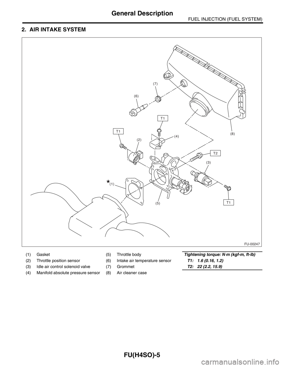
2. AIR INTAKE SYSTEM
(1) Gasket (5) Throttle bodyTightening torque: N⋅m (kgf-m, ft-lb)
(2) Throttle position sensor (6) Intake air temperature sensorT1: 1.6 (0.16, 1.2)
(3) Idle air control solenoid valve (7) GrommetT2: 22 (2.2, 15.9)
(4) Manifold absolute pressure sensor (8) Air cleaner case
FU-00247
(2)
(3) (4)
(5) (1)
T1
T1
T1
T2
(8) (6)(7)
Page 795 of 2870

FU(H4SO)-13
FUEL INJECTION (FUEL SYSTEM)
Throttle Body
2. Throttle Body
A: REMOVAL
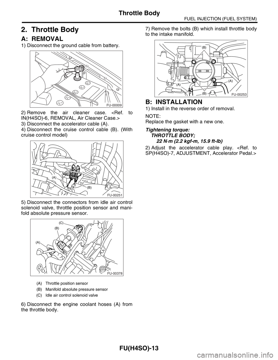
1) Disconnect the ground cable from battery.
2) Remove the air cleaner case.
3) Disconnect the accelerator cable (A).
4) Disconnect the cruise control cable (B). (With
cruise control model)
5) Disconnect the connectors from idle air control
solenoid valve, throttle position sensor and mani-
fold absolute pressure sensor.
6) Disconnect the engine coolant hoses (A) from
the throttle body.7) Remove the bolts (B) which install throttle body
to the intake manifold.
B: INSTALLATION
1) Install in the reverse order of removal.
NOTE:
Replace the gasket with a new one.
Tightening torque:
THROTTLE BODY;
22 N
⋅m (2.2 kgf-m, 15.9 ft-lb)
2) Adjust the accelerator cable play.
(A) Throttle position sensor
(B) Manifold absolute pressure sensor
(C) Idle air control solenoid valve
FU-00009
FU-00251
(B)
(A)
FU-00378
(B)
(A)(C)
FU-00253
(B)
(B)
(A)(A)
Page 796 of 2870

FU(H4SO)-14
FUEL INJECTION (FUEL SYSTEM)
Intake Manifold
3. Intake Manifold
A: REMOVAL
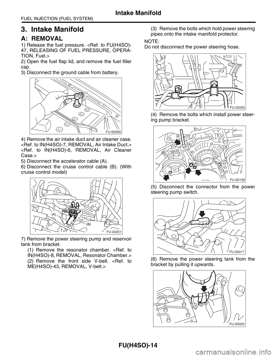
1) Release the fuel pressure.
TION, Fuel.>
2) Open the fuel flap lid, and remove the fuel filler
cap.
3) Disconnect the ground cable from battery.
4) Remove the air intake duct and air cleaner case.
5) Disconnect the accelerator cable (A).
6) Disconnect the cruise control cable (B). (With
cruise control model)
7) Remove the power steering pump and reservoir
tank from bracket.
(1) Remove the resonator chamber.
(2) Remove the front side V-belt.
pipes onto the intake manifold protector.
NOTE:
Do not disconnect the power steering hose.
(4) Remove the bolts which install power steer-
ing pump bracket.
(5) Disconnect the connector from the power
steering pump switch.
(6) Remove the power steering tank from the
bracket by pulling it upwards.
FU-00009
FU-00251
(B)
(A)
FU-00255
FU-00139
FU-00017
FU-00020