2004 SUBARU FORESTER fuel pressure
[x] Cancel search: fuel pressurePage 966 of 2870

ME(H4SO)-95
MECHANICAL
Engine Trouble in General
10. Excessive fuel consump-
tionEngine control system
Intake system Dirty air cleaner element A
Belt Defective timing B
Compression Incorrect valve clearance B
Loosened spark plugs or defective gasket C
Loosened cylinder head bolts or defective gasket C
Improper valve seating B
Defective valve stem C
Worn or broken valve spring C
Worn or stuck piston rings, cylinder and piston B
Incorrect valve timing B
Lubrication system Incorrect oil pressure C
Cooling system Over cooling C
Others Accelerator cable out of adjustment B TROUBLE PROBLEM PARTS, ETC. POSSIBLE CAUSE RANK
Page 967 of 2870

ME(H4SO)-96
MECHANICAL
Engine Noise
23.Engine Noise
A: INSPECTION
NOTE*:
When disconnecting fuel injector connector, the malfunction indicator light illuminates and DTC is stored in ECM memory.
Therefore, carry out the clear memory mode
Regular clicking soundSound increases as engine
speed increases. Valve mechanism is defective.
Incorrect valve clearance
Worn valve rocker
Worn camshaft
Broken valve spring
Heavy and dull clankOil pressure is low. Worn crankshaft main bearing
Worn connecting rod bearing (big end)
Oil pressure is normal. Loose flywheel mounting bolts
Damaged engine mounting
High-pitched clank (Spark
knock)Sound is noticeable when
accelerating with an overload. Ignition timing advanced
Accumulation of carbon inside combustion chamber
Wrong spark plug
Improper gasoline
Clank when engine speed is
medium (1,000 to 2,000 rpm).Sound is reduced when fuel
injector connector of noisy cyl-
inder is disconnected.
(NOTE*) Worn crankshaft main bearing
Worn bearing at crankshaft end of connecting rod
Knocking sound when engine
is operating under idling speed
and engine is warmSound is reduced when fuel
injector connector of noisy cyl-
inder is disconnected.
(NOTE*) Worn cylinder liner and piston ring
Broken or stuck piston ring
Worn piston pin and hole at piston end of connecting rod
Sound is not reduced if each
fuel injector connector is dis-
connected in turn. (NOTE*) Unusually worn valve lifter
Worn cam gear
Worn camshaft journal bore in crankcase
Squeaky sound — Insufficient generator lubrication
Rubbing sound — Defective generator brush and rotor contact
Gear scream when starting
engine— Defective ignition starter switch
Worn gear and starter pinion
Sound like polishing glass with
a dry cloth— Loose drive belt
Defective water pump shaft
Hissing sound — Loss of compression
Air leakage in air intake system, hoses, connections or mani-
folds
Timing belt noise — Loose timing belt
Belt contacting case/adjacent part
Valve tappet noise — Incorrect valve clearance
Page 1026 of 2870

CO(H4SO)-43
COOLING
Engine Cooling System Trouble in General
12.Engine Cooling System Trouble in General
A: INSPECTION
Trouble Possible cause Corrective action
Over-heatinga. Insufficient engine coolantReplenish the engine coolant, inspect for leakage, and
repair.
b. Loose timing belt Repair or replace the timing belt tensioner.
c. Oil on drive belt Replace.
d. Malfunction of thermostat Replace.
e. Malfunction of water pump Replace.
f. Clogged engine coolant passage Clean.
g. Improper ignition timingInspect and repair the ignition control system.
h. Clogged or leaking radiator Clean or repair, or replace.
i. Improper engine oil in engine coolant Replace the engine coolant.
j. Air/fuel mixture ratio too leanInspect and repair the fuel injection system.
k. Excessive back pressure in exhaust system Clean or replace.
l. Insufficient clearance between piston and cylinder Adjust or replace.
m. Slipping clutch Repair or replace.
n. Dragging brake Adjust.
o. Defective thermostat Replace.
p. Malfunction of radiator fanInspect the radiator fan relay, engine coolant tempera-
ture sensor or radiator motor and replace there.
Over-coolinga. Atmospheric temperature extremely low Partly cover the radiator front area.
b. Defective thermostat Replace.
Engine coolant
leaks.a. Loosened or damaged connecting units on hoses Repair or replace.
b. Leakage from water pump Replace.
c. Leakage from water pipe Repair or replace.
d. Leakage around cylinder head gasket Retighten the cylinder head bolts or replace gasket.
e. Damaged or cracked cylinder head and crankcase Repair or replace.
f. Damaged or cracked thermostat case Repair or replace.
g. Leakage from radiator Repair or replace.
Noisea. Defective drive belt Replace.
b. Defective radiator fan Replace.
c. Defective water pump bearing Replace the water pump.
d. Defective water pump mechanical seal Replace the water pump.
Page 1103 of 2870

EN(H4SO)-5
ENGINE (DIAGNOSTIC)
Check List for Interview
2. CHECK LIST No. 2
Check the following items about the vehicle’s state when malfunction indicator light turns on.
NOTE:
Use copies of this page for interviewing customers.
a) Other warning lights or indicators turn on. ❏ Yes / ❏ No
❏ Low fuel warning light
❏ Charge indicator light
❏ AT diagnostic indicator light
❏ ABS Warning light
❏ Oil pressure indicator light
b) Fuel level
Lack of gasoline: ❏ Yes / ❏ No
Indicator position of fuel gauge:
Experienced running out of fuel: ❏ Ye s / ❏ No
c) Intentional connecting or disconnecting of harness connectors or spark plug cords: ❏ Yes / ❏ No
What:
d) Intentional connecting or disconnecting of hoses: ❏ Ye s / ❏ No
What:
e) Installing of other parts except genuine parts: ❏ Ye s / ❏ No
What:
Where:
f) Occurrence of noise: ❏ Yes / ❏ No
From where:
What kind:
g) Occurrence of smell: ❏ Yes / ❏ No
From where:
What kind:
h) Intrusion of water into engine compartment or passenger compartment: ❏ Yes / ❏ No
i) Troubles occurred
❏ Engine does not start.
❏ Engine stalls during idling.
❏ Engine stalls while driving.
❏ Engine speed decreases.
❏ Engine speed does not decrease.
❏ Rough idling
❏ Poor acceleration
❏ Back fire
❏ After fire
❏ Does not shift.
❏ Excessive shift shock
Page 1105 of 2870
EN(H4SO)-7
ENGINE (DIAGNOSTIC)
General Description
The antenna feeder must be placed as far
apart as possible from the ECM and MFI har-
ness.
Carefully adjust the antenna for correct
matching.
When mounting a large power type radio, pay
special attention to the three items above men-
tioned.
Incorrect installation of the radio may affect
the operation of the ECM.
13) Before disconnecting the fuel hose, disconnect
the fuel pump connector and crank the engine for
more than five seconds to release pressure in the
fuel system. If engine starts during this operation,
run it until it stops.
14) Problems in the electronic-controlled automatic
transmission may be caused by failure of the en-
gine, the electronic control system, the transmis-
sion proper, or by a combination of these. These
three causes must be distinguished clearly when
performing diagnostics.
15) Diagnostics should be conducted by rotating
with simple, easy operations and proceeding to
complicated, difficult operations. The most impor-
tant thing in diagnostics is to understand the cus-
tomer’s complaint, and distinguish between the
three causes.
16) In AT models, do not continue the stall for more
than five seconds. (from closed throttle, fully open
throttle to stall engine speed.)
17) On the model with ABS, when performing driv-
ing test in jacked-up or lifted-up position, some-
times the warning light may be lit, but this is not a
malfunction of the system. The reason for this is the
speed difference between the front and rear
wheels. After diagnosis of engine control system,
perform the ABS memory clearance procedure of
self-diagnosis function.
B: INSPECTION
Before performing diagnostics, check the following
items which might affect engine problems:
1. BATTERY
1) Measure battery voltage and specific gravity of
electrolyte.
Standard voltage: 12 V
Specific gravity: Above 1.260
2) Check the condition of the main and other fuses,
and harnesses and connectors. Also check for
proper grounding.
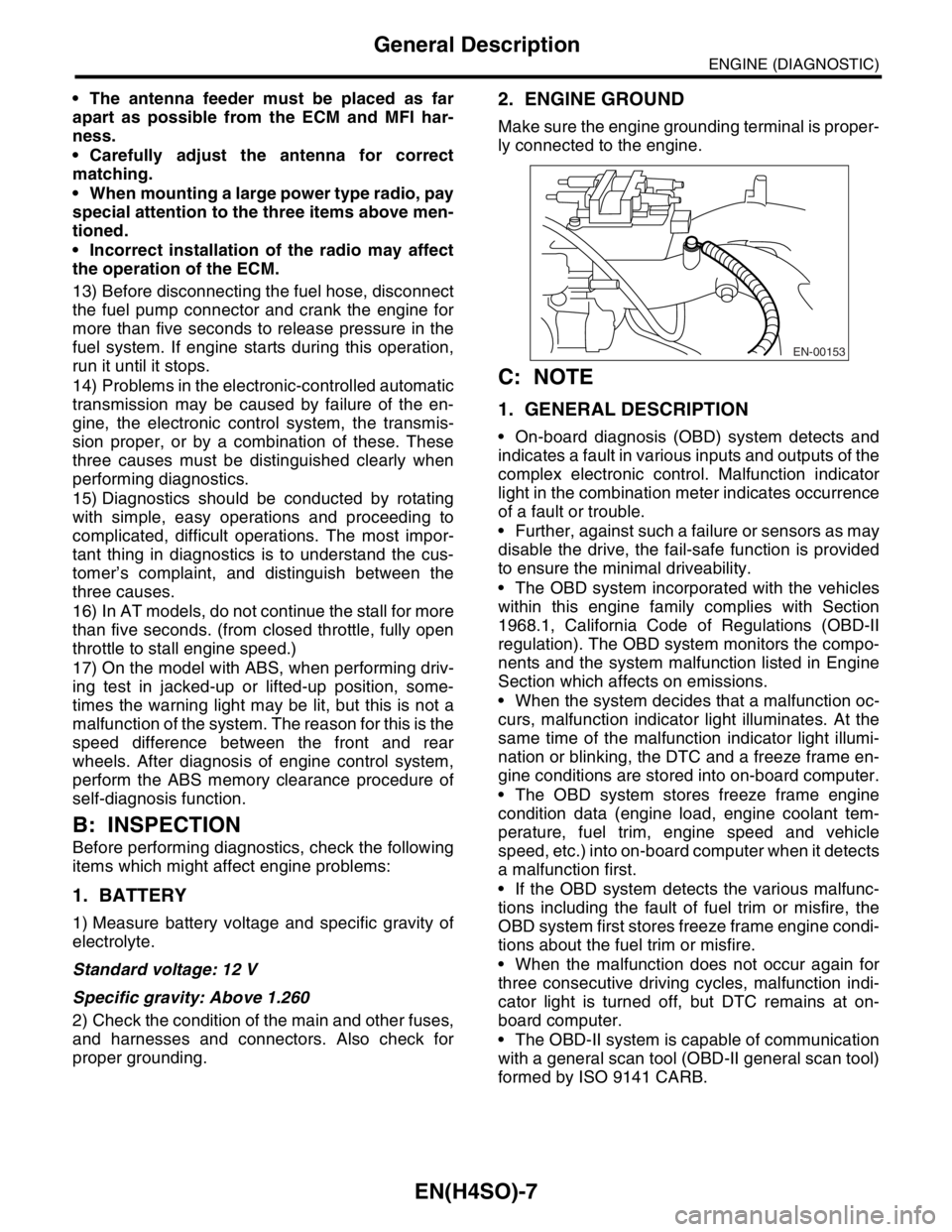
2. ENGINE GROUND
Make sure the engine grounding terminal is proper-
ly connected to the engine.
C: NOTE
1. GENERAL DESCRIPTION
On-board diagnosis (OBD) system detects and
indicates a fault in various inputs and outputs of the
complex electronic control. Malfunction indicator
light in the combination meter indicates occurrence
of a fault or trouble.
Further, against such a failure or sensors as may
disable the drive, the fail-safe function is provided
to ensure the minimal driveability.
The OBD system incorporated with the vehicles
within this engine family complies with Section
1968.1, California Code of Regulations (OBD-II
regulation). The OBD system monitors the compo-
nents and the system malfunction listed in Engine
Section which affects on emissions.
When the system decides that a malfunction oc-
curs, malfunction indicator light illuminates. At the
same time of the malfunction indicator light illumi-
nation or blinking, the DTC and a freeze frame en-
gine conditions are stored into on-board computer.
The OBD system stores freeze frame engine
condition data (engine load, engine coolant tem-
perature, fuel trim, engine speed and vehicle
speed, etc.) into on-board computer when it detects
a malfunction first.
If the OBD system detects the various malfunc-
tions including the fault of fuel trim or misfire, the
OBD system first stores freeze frame engine condi-
tions about the fuel trim or misfire.
When the malfunction does not occur again for
three consecutive driving cycles, malfunction indi-
cator light is turned off, but DTC remains at on-
board computer.
The OBD-II system is capable of communication
with a general scan tool (OBD-II general scan tool)
formed by ISO 9141 CARB.
EN-00153
Page 1106 of 2870
EN(H4SO)-8
ENGINE (DIAGNOSTIC)
General Description
The OBD-II diagnostics procedure is different
from the usual diagnosis procedure. When trouble-
shooting the OBD-II models, connect Subaru Se-
lect Monitor or the OBD-II general scan tool to the
vehicle.
2. ENGINE AND EMISSION CONTROL SYS-
TEM
MFI system is a system that supplies the opti-
mum air-fuel mixture to the engine for all the vari-
ous operating conditions through the use of the
latest electronic technology.
With this system fuel, which is pressurized at a con-
stant pressure, is injected into the intake air pas-
sage of the cylinder head. The injection quantity of
fuel is controlled by an intermittent injection system
where the electro-magnetic injection valve (fuel in-
jector) opens only for a short period of time, de-
pending on the quantity of air required for one cycle
of operation. In actual operation, the injection quan-
tity is determined by the duration of an electric sig-
nal applied to the fuel injector and this permits
simple, yet highly precise metering of the fuel.
Further, all the operating conditions of the engine
are converted into electric signals, and this results
in additional features of the system, such as large
improved adaptability, easier addition of compen-
sating element, etc.The MFI system also has the following features:
Reduced emission of harmful exhaust gases.
Reduced in fuel consumption.
Increased engine output.
Superior acceleration and deceleration.
Excellent engine start and warm-up perfor-
mance by the correction of engine coolant tem-
perature and intake air temperature.3. AUTOMATIC TRANSMISSION AND
ELECTRONIC-HYDRAULIC CONTROL SYS-
TEM
The electronic-hydraulic control system consists of
various sensors and switches, TCM and the hy-
draulic controller including solenoid valves. The
system controls the transmission body including
shift control, lock-up control, overrunning clutch
control, line pressure control and shift timing con-
trol. It also controls the AWD transfer clutch. In oth-
er words, the system detects various operating
conditions from various input signals and sends
output signals to shift solenoids 1, 2 and low clutch
timing solenoid and 2-4 brake timing solenoid, line
pressure duty solenoid, lock-up duty solenoid,
transfer duty solenoid and 2-4 brake duty solenoid
(a total of eight solenoids).
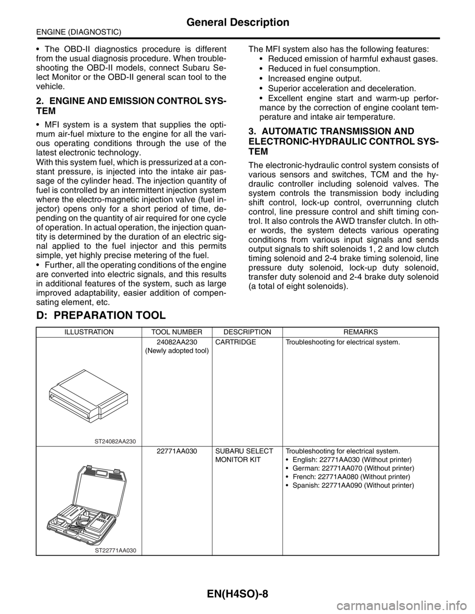
D: PREPARATION TOOL
ILLUSTRATION TOOL NUMBER DESCRIPTION REMARKS
24082AA230
(Newly adopted tool)CARTRIDGE Troubleshooting for electrical system.
22771AA030 SUBARU SELECT
MONITOR KITTroubleshooting for electrical system.
English: 22771AA030 (Without printer)
German: 22771AA070 (Without printer)
French: 22771AA080 (Without printer)
Spanish: 22771AA090 (Without printer)
ST24082AA230
ST22771AA030
Page 1125 of 2870
EN(H4SO)-27
ENGINE (DIAGNOSTIC)
OBD-II General Scan Tool
9. OBD-II General Scan Tool
A: OPERATION
1. HOW TO USE OBD-II GENERAL SCAN
TOOL
1) Prepare a general scan tool (OBD-II general
scan tool) required by SAE J1978.
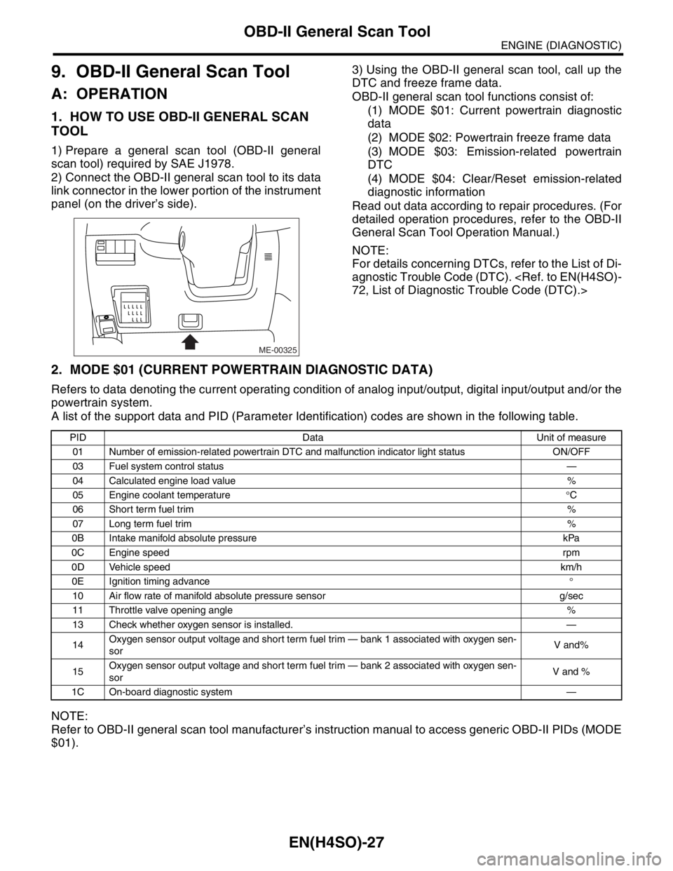
2) Connect the OBD-II general scan tool to its data
link connector in the lower portion of the instrument
panel (on the driver’s side).3) Using the OBD-II general scan tool, call up the
DTC and freeze frame data.
OBD-II general scan tool functions consist of:
(1) MODE $01: Current powertrain diagnostic
data
(2) MODE $02: Powertrain freeze frame data
(3) MODE $03: Emission-related powertrain
DTC
(4) MODE $04: Clear/Reset emission-related
diagnostic information
Read out data according to repair procedures. (For
detailed operation procedures, refer to the OBD-II
General Scan Tool Operation Manual.)
NOTE:
For details concerning DTCs, refer to the List of Di-
agnostic Trouble Code (DTC).
2. MODE $01 (CURRENT POWERTRAIN DIAGNOSTIC DATA)
Refers to data denoting the current operating condition of analog input/output, digital input/output and/or the
powertrain system.
A list of the support data and PID (Parameter Identification) codes are shown in the following table.
NOTE:
Refer to OBD-II general scan tool manufacturer’s instruction manual to access generic OBD-II PIDs (MODE
$01).
ME-00325
PID Data Unit of measure
01 Number of emission-related powertrain DTC and malfunction indicator light status ON/OFF
03 Fuel system control status—
04 Calculated engine load value%
05 Engine coolant temperature°C
06 Short term fuel trim%
07 Long term fuel trim%
0B Intake manifold absolute pressure kPa
0C Engine speedrpm
0D Vehicle speedkm/h
0E Ignition timing advance°
10 Air flow rate of manifold absolute pressure sensor g/sec
11 Throttle valve opening angle%
13 Check whether oxygen sensor is installed. —
14Oxygen sensor output voltage and short term fuel trim — bank 1 associated with oxygen sen-
sorV and%
15Oxygen sensor output voltage and short term fuel trim — bank 2 associated with oxygen sen-
sorV and %
1C On-board diagnostic system—
Page 1126 of 2870

EN(H4SO)-28
ENGINE (DIAGNOSTIC)
OBD-II General Scan Tool
3. MODE $02 (POWERTRAIN FREEZE FRAME DATA)
Refers to data denoting the operating condition when trouble is sensed by the on-board diagnosis system.
A list of the support data and PID (Parameter Identification) codes are shown in the following table.
NOTE:
Refer to OBD-II general scan tool manufacturer’s instruction manual to access freeze frame data (MODE
$02).
4. MODE $03 (EMISSION-RELATED POWERTRAIN DIAGNOSTIC TROUBLE CODES)
Refer to “Read Diagnostic Trouble Code (DTC)” for information about data denoting emission-related pow-
ertrain DTC.
5. MODE $04 (CLEAR/RESET EMISSION-RELATED DIAGNOSTIC INFORMATION)
Refers to the mode used to clear or reset emission-related diagnostic information (OBD-II trouble diagnostic
information).
NOTE:
Refer to OBD-II general scan tool manufacturer’s instruction manual to clear or reset emission-related diag-
nostic information (MODE $04).
PID Data Unit of measure
02 DTC that caused CARB required freeze frame data storage —
03 Fuel system control status—
04 Calculated engine load value%
05 Engine coolant temperature°C
06 Short term fuel trim%
07 Long term fuel trim%
0B Intake manifold absolute pressure kPa
0C Engine speedrpm
0D Vehicle speedkm/h