2004 SUBARU FORESTER fuel pressure
[x] Cancel search: fuel pressurePage 1238 of 2870

EN(H4SO)-140
ENGINE (DIAGNOSTIC)
Diagnostic Procedure with Diagnostic Trouble Code (DTC)
7 CHECK FUEL PRESSURE.
After connecting the pressure regulator vac-
uum hose, measure fuel pressure.
Warning:
Release fuel pressure before removing the
fuel pressure gauge.
N
OTE:
If fuel pressure does not increase, squeeze
fuel return hose 2 to 3 times, then measure
fuel pressure again.
If out of specification as measured at this
step, check or replace pressure regulator and
pressure regulator vacuum hose.Is measured value 206 — 235
kPa (2.1 — 2.4 kg/cm
2, 30 —
34 psi)?Go to step 8.Repair the follow-
ing items.
Fuel pressure is
too high:
Faulty pres-
sure regulator
Clogged fuel
return line or
bent hose
Fuel pressure is
too low:
Faulty pres-
sure regulator
Improper fuel
pump discharge
Clogged fuel
supply line
8 CHECK ENGINE COOLANT TEMPERATURE
SENSOR.
1) Start the engine and warm-up completely.
2) Read the data of engine coolant tempera-
ture sensor signal using Subaru Select Monitor
or the OBD-II scan tool.
NOTE:
Subaru Select Monitor
For detailed operation procedure, refer to the
“READ CURRENT DATA FOR ENGINE”.
OBD-II scan tool
For detailed operation procedures, refer to the
OBD-II Scan Tool Instruction Manual.Is the engine coolant tempera-
ture 70 — 100°C (158 —
212°F)?Go to step 9.Replace the
engine coolant
temperature sen-
sor.
Engine Coolant
Temperature Sen-
sor.>
9 CHECK MANIFOLD PRESSURE SENSOR
SIGNAL.
1) Start and warm-up the engine until engine
coolant temperature is greater than 60°C
(140°F).
2) Shift the select lever to “N” or “P” range.
3) Turn the A/C switch to OFF.
4) Turn all accessory switches to OFF.
5) Read the data of manifold absolute pres-
sure sensor signal using Subaru Select Moni-
tor or OBD-II scan tool.
NOTE:
Subaru Select Monitor
For detailed operation procedure, refer to the
“READ CURRENT DATA FOR ENGINE”.
OBD-II scan tool
For detailed operation procedures, refer to the
OBD-II Scan Tool Instruction Manual.Is the measurement value at
idling: 24.0 — 41.3 kPa (180 —
310 mmHg, 7.09 — 12.20
inHg), at ignition ON: 73.3 —
106.6 kPa (550 — 800 mmHg,
21.65 — 31.50 inHg)?Contact the SUB-
ARU dealer.
NOTE:
Inspection by DTM
is required,
because probable
cause is deteriora-
tion of multiple
parts.Replace the mani-
fold absolute pres-
sure sensor.
Manifold Absolute
Pressure Sensor.> Step Check Yes No
Page 1353 of 2870

EN(H4SO)-255
ENGINE (DIAGNOSTIC)
General Diagnostic Table
20.General Diagnostic Table
A: INSPECTION
1. ENGINE
NOTE:
Malfunction of parts other than those listed is also possible.
Symptom Problem parts
1. Engine stalls during idling.1) Idle air control solenoid valve
2) Manifold absolute pressure sensor
3) Intake air temperature sensor
4) Ignition parts (*1)
5) Engine coolant temperature sensor (*2)
6) Crankshaft position sensor (*3)
7) Camshaft position sensor (*3)
8) Fuel injection parts (*4)
2. Rough idling1) Idle air control solenoid valve
2) Manifold absolute pressure sensor
3) Intake air temperature sensor
4) Engine coolant temperature sensor (*2)
5) Ignition parts (*1)
6) Air intake system (*5)
7) Fuel injection parts (*4)
8) Throttle position sensor
9) Crankshaft position sensor (*3)
10) Camshaft position sensor (*3)
11) Oxygen sensor
12) Fuel pump and fuel pump relay
3. Engine does not return to idle.1) Idle air control solenoid valve
2) Engine coolant temperature sensor
3) Accelerator cable (*6)
4) Throttle position sensor
5) Manifold absolute pressure sensor
6) Intake air temperature sensor
4. Poor acceleration1) Manifold absolute pressure sensor
2) Intake air temperature sensor
3) Throttle position sensor
4) Fuel injection parts (*4)
5) Fuel pump and fuel pump relay
6) Engine coolant temperature sensor (*2)
7) Crankshaft position sensor (*3)
8) Camshaft position sensor (*3)
9) A/C switch and A/C cut relay
10) Engine torque control signal circuit
11) Ignition parts (*1)
5. Engine stalls or engine sags or hesitates at
acceleration.1) Manifold absolute pressure sensor
2) Intake air temperature sensor
3) Engine coolant temperature sensor (*2)
4) Crankshaft position sensor (*3)
5) Camshaft position sensor (*3)
6) Purge control solenoid valve
7) Fuel injection parts (*4)
8) Throttle position sensor
9) Fuel pump and fuel pump relay
Page 1354 of 2870

EN(H4SO)-256
ENGINE (DIAGNOSTIC)
General Diagnostic Table
*1: Check ignition coil & ignitor ASSY and spark plug.
*2: Indicate the symptom occurring only in cold temperatures.
*3: Ensure the secure installation.
*4: Check fuel injector, fuel pressure regulator and fuel filter.
*5: Inspect air leak in air intake system.
*6: Adjust the accelerator cable.
2. AUTOMATIC TRANSMISSION
NOTE:
Check general diagnostics table with non-conformity symptom for automatic transmission.
6. Surging1) Intake manifold pressure sensor
2) Intake air temperature sensor
3) Manifold absolute pressure sensor
4) Engine coolant temperature sensor (*2)
5) Crankshaft position sensor (*3)
6) Camshaft position sensor (*3)
7) Fuel injection parts (*4)
8) Throttle position sensor
9) Fuel pump and fuel pump relay
7. Spark knock1) Intake manifold pressure sensor
2) Intake air temperature sensor
3) Manifold absolute pressure sensor
4) Engine coolant temperature sensor
5) Knock sensor
6) Fuel injection parts (*4)
7) Fuel pump and fuel pump relay
8. After burning in exhaust system1) Intake manifold pressure sensor
2) Intake air temperature sensor
3) Manifold absolute pressure sensor
4) Engine coolant temperature sensor (*2)
5) Fuel injection parts (*4)
6) Fuel pump and fuel pump relay Symptom Problem parts
Page 1356 of 2870

FUEL INJECTION (FUEL SYSTEM)
FU(H4DOTC)
Page
1. General Description ....................................................................................2
2. Throttle Body .............................................................................................13
3. Intake Manifold ..........................................................................................14
4. Engine Coolant Temperature Sensor........................................................29
5. Crankshaft Position Sensor.......................................................................30
6. Camshaft Position Sensor.........................................................................31
7. AVCS Camshaft Position Sensor ..............................................................32
8. Knock Sensor ............................................................................................33
9. Throttle Position Sensor ............................................................................34
10. Mass Air Flow and Intake Air Temperature Sensor ..................................35
11. Manifold Absolute Pressure Sensor ..........................................................36
12. Idle Air Control Solenoid Valve .................................................................37
13. Fuel Injector ..............................................................................................38
14. Tumble Generator Valve Assembly ..........................................................42
15. Tumble Generator Valve Actuator.............................................................43
16. Wastegate Control Solenoid Valve Assembly ...........................................44
17. Front Oxygen (A/F) Sensor .......................................................................45
18. Rear Oxygen Sensor.................................................................................47
19. Exhaust Temperature Sensor ...................................................................49
20. Engine Control Module (ECM) ..................................................................50
21. Main Relay ................................................................................................51
22. Fuel Pump Relay.......................................................................................52
23. Fuel Pump Control Unit .............................................................................53
24. Fuel ...........................................................................................................54
25. Fuel Tank ..................................................................................................55
26. Fuel Filler Pipe ..........................................................................................58
27. Fuel Pump .................................................................................................62
28. Fuel Level Sensor .....................................................................................64
29. Fuel Sub Level Sensor ..............................................................................65
30. Fuel Filter ..................................................................................................67
31. Fuel Cut Valve...........................................................................................68
32. Fuel Damper Valve ...................................................................................69
33. Fuel Delivery, Return and Evaporation Lines............................................70
34. Fuel System Trouble in General ...............................................................73
Page 1357 of 2870

FU(H4DOTC)-2
FUEL INJECTION (FUEL SYSTEM)
General Description
1. General Description
A: SPECIFICATION
Fuel tankCapacity 602 (15.9 US gal, 13.2 Imp gal)
Location Under rear seat
Fuel pumpType Impeller
Shutoff discharge pressure
450 — 677 kPa (4.59 — 6.9 kg/cm
2, 65.27 — 98.2 psi)
Discharge flowMore than 1302 (34.3 US gal, 28.6 Imp gal)/h
[12 V at 300 kPa (3.06 kg/cm
2, 43.5 psi)]
Fuel filterCartridge type
Page 1359 of 2870

FU(H4DOTC)-4
FUEL INJECTION (FUEL SYSTEM)
General Description
(1) Fuel pipe ASSY (13) Insulator (24) Purge hose
(2) Fuel hose (14) Fuel injector pipe (25) Tumble generator valve actuator
(3) Clamp (15) Pressure regulator
(4) Purge control solenoid valve (16) Pressure regulator hoseTightening torque: N
⋅m (kgf-m, ft-lb)
(5) Vacuum hose (17) Fuel pipe protector RHT1: 5 (0.5, 3.7)
(6) Vacuum control hose (18) Blow-by hose stayT2: 6.4 (0.65, 4.7)
(7) Intake manifold gasket (19) Intake manifoldT3: 8.25 (0.84, 6.1)
(8) Guide pin (20) Wastegate control solenoid valve
ASSYT4: 16 (1.6, 11.8)
(9) Tumble generator valve ASSY T5: 17 (1.7, 12.5)
(10) Gasket (21) Fuel pipe protector LHT6: 19 (1.9, 14.0)
(11) Accelerator cable bracket (22) NippleT7: 25 (2.5, 18.4)
(12) Fuel injector (23) Purge valve
Page 1360 of 2870
FU(H4DOTC)-5
FUEL INJECTION (FUEL SYSTEM)
General Description
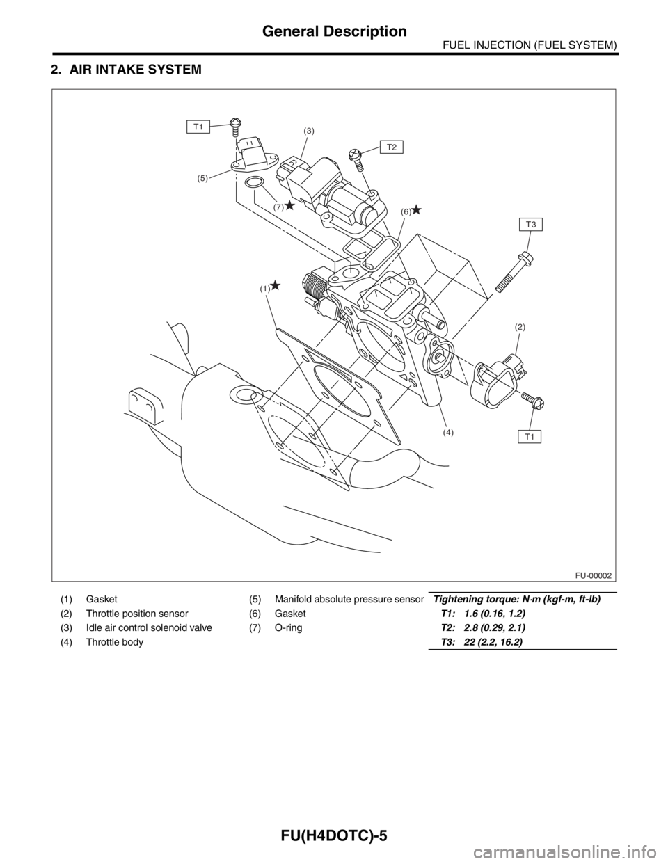
2. AIR INTAKE SYSTEM
(1) Gasket (5) Manifold absolute pressure sensorTightening torque: N⋅m (kgf-m, ft-lb)
(2) Throttle position sensor (6) GasketT1: 1.6 (0.16, 1.2)
(3) Idle air control solenoid valve (7) O-ringT2: 2.8 (0.29, 2.1)
(4) Throttle bodyT3: 22 (2.2, 16.2)
FU-00002
(1)
(5)
(7)
(2)
(4)
T1
T1
T3
(3)
(6)
T2
Page 1368 of 2870
FU(H4DOTC)-13
FUEL INJECTION (FUEL SYSTEM)
Throttle Body
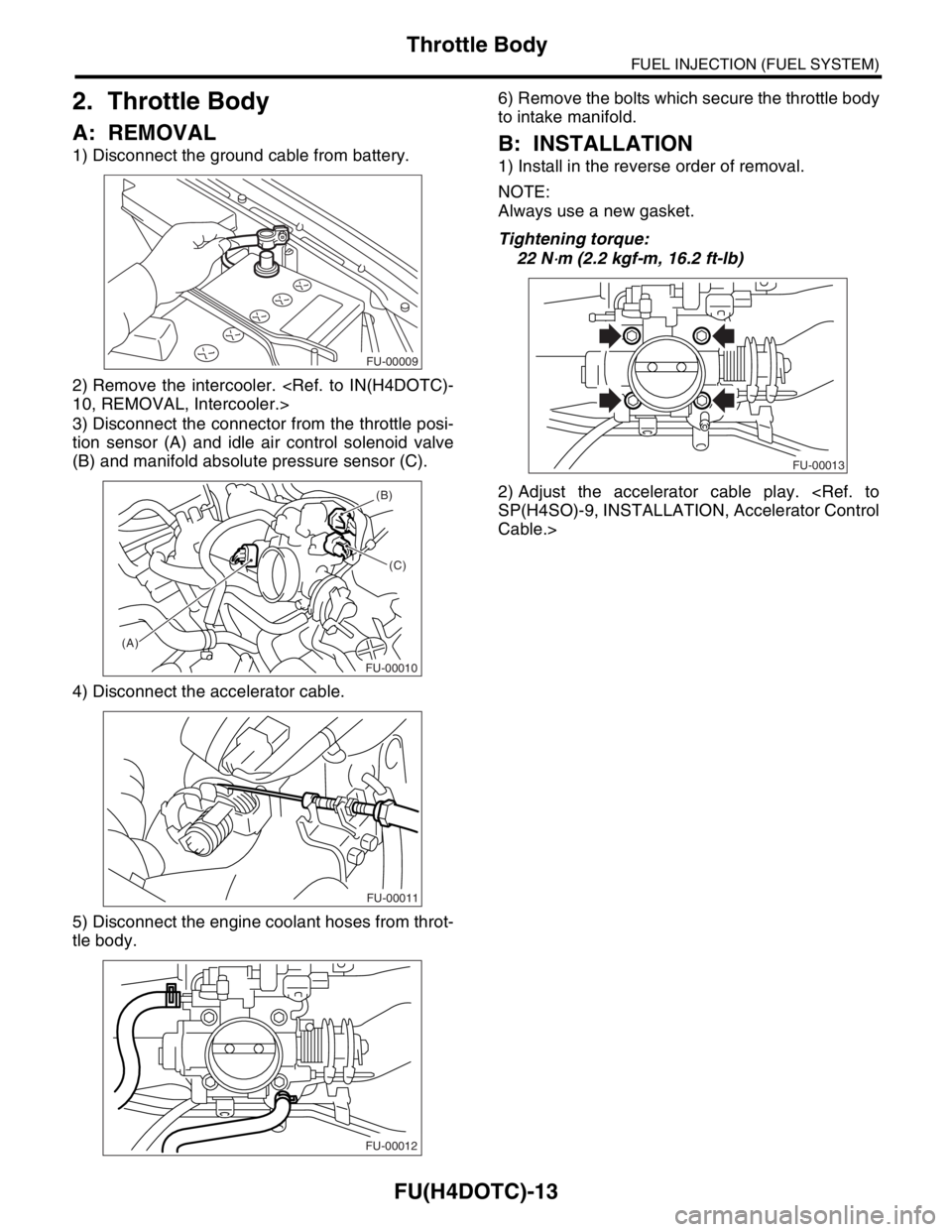
2. Throttle Body
A: REMOVAL
1) Disconnect the ground cable from battery.
2) Remove the intercooler.
3) Disconnect the connector from the throttle posi-
tion sensor (A) and idle air control solenoid valve
(B) and manifold absolute pressure sensor (C).
4) Disconnect the accelerator cable.
5) Disconnect the engine coolant hoses from throt-
tle body.6) Remove the bolts which secure the throttle body
to intake manifold.B: INSTALLATION
1) Install in the reverse order of removal.
NOTE:
Always use a new gasket.
Tightening torque:
22 N
⋅m (2.2 kgf-m, 16.2 ft-lb)
2) Adjust the accelerator cable play.
Cable.>
FU-00009
(A)(B)
(C)
FU-00010
FU-00011
FU-00012
FU-00013