2004 SUBARU FORESTER gas type
[x] Cancel search: gas typePage 23 of 2870

AC-21
HVAC SYSTEM (HEATER, VENTILATOR AND A/C)
General Description
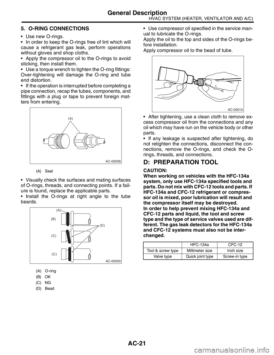
5. O-RING CONNECTIONS
Use new O-rings.
In order to keep the O-rings free of lint which will
cause a refrigerant gas leak, perform operations
without gloves and shop cloths.
Apply the compressor oil to the O-rings to avoid
sticking, then install them.
Use a torque wrench to tighten the O-ring fittings:
Over-tightening will damage the O-ring and tube
end distortion.
If the operation is interrupted before completing a
pipe connection, recap the tubes, components, and
fittings with a plug or tape to prevent foreign mat-
ters from entering.
Visually check the surfaces and mating surfaces
of O-rings, threads, and connecting points. If a fail-
ure is found, replace the applicable parts.
Install the O-rings at right angle to the tube
beards. Use compressor oil specified in the service man-
ual to lubricate the O-rings.
Apply the oil to the top and sides of the O-rings be-
fore installation.
Apply compressor oil to the bead of tube.
After tightening, use a clean cloth to remove ex-
cess compressor oil from the connections and any
oil which may have run on the vehicle body or other
parts.
If any leakage is suspected after tightening, do
not retighten the connections, disconnect the con-
nections, remove the O-rings, and check the O-
rings, threads, and connections.
D: PREPARATION TOOL
CAUTION:
When working on vehicles with the HFC-134a
system, only use HFC-134a specified tools and
parts. Do not mix with CFC-12 tools and parts. If
HFC-134a and CFC-12 refrigerant or compres-
sor oil is mixed, poor lubrication will result and
the compressor itself may be destroyed.
In order to help prevent mixing HFC-134a and
CFC-12 parts and liquid, the tool and screw
type and the type of service valves used are dif-
ferent. The gas leak detectors for the HFC-134a
and CFC-12 systems must also not be inter-
changed.(A) Seal
(A) O-ring
(B) OK
(C) NG
(D) Bead
(A)
AC-00008
AC-00009
(D) (B)
(C)
(C)
(A)
HFC-134a CFC-12
Tool & screw type Millimeter size Inch size
Valve type Quick joint type Screw-in type
AC-00010
Page 691 of 2870

SPC-2
SPECIFICATION
Forester
1. Forester
A: DIMENSIONS
★: With sunroof
B: ENGINE
Model 2.0 L Non-turbo 2.0 L Turbo 2.5 L Non-turbo 2.5 L Turbo
Overall length mm (in) 4,450 (175.2)
Overall width mm (in) 1,735 (68.3)
Overall height (at C.W.) mm (in) 1,590 (62.6) 1,585 (62.4) 1,590 (62.6)
CompartmentLength mm (in) 1,795 (70.7)
Width mm (in) 1,455 (57.3)
Height mm (in)
1,245 (49.0), 1,210 (47.6)
★
Wheelbase mm (in) 2,525 (99.4)
Tread Front mm (in) 1,495 (58.9)
Rear mm (in) 1,485 (58.5)
Minimum road clearance mm (in) 190 (7.5) 195 (7.7) 200 (7.9)
Model 2.0 L Non-turbo 2.0 L Turbo 2.5 L Non-turbo 2.5 L Turbo
Engine type Horizontally opposed, liquid cooled, 4-cylinder, 4-stroke gasoline engine
Valve arrangement Overhead camshaft type
Bore×Stroke mm (in) 92×75 (3.62×2.95) 99.5×79 (3.92×3.11)
Displacement
cm
3 (cu in)1,994 (121.67) 2,457 (149.94)
Compression ratio 10.0±0.2 8.0±0.2 10.0±0.2 8.2±0.2
Firing order 1 — 3 — 2 — 4
Idle speed at Park or Neu-
tral positionrpm 650±100 700±100 650±100 700±100
Maximum output kW (PS)/rpm 92 (125)/5,600 130 (177)/5,600 115 (156)/5,600 155 (211)/5,600
Maximum torque N⋅m (kgf-m, ft-lb)/rpm184 (18.8, 41.4)/
3,600245 (25.0, 55.1)/
3,200223 (22.7, 50.1)/
3,600320 (32.6, 71.8)/
3,600
Page 763 of 2870

PM-26
PERIODIC MAINTENANCE SERVICE
ATF
16.ATF
A: INSPECTION
CAUTION:
The level of ATF varies with fluid temperature.
Pay attention to the fluid temperature when
checking ATF level.
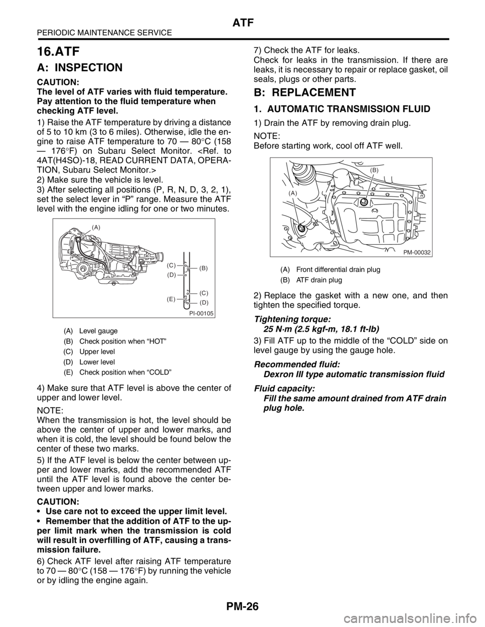
1) Raise the ATF temperature by driving a distance
of 5 to 10 km (3 to 6 miles). Otherwise, idle the en-
gine to raise ATF temperature to 70 — 80°C (158
— 176°F) on Subaru Select Monitor.
TION, Subaru Select Monitor.>
2) Make sure the vehicle is level.
3) After selecting all positions (P, R, N, D, 3, 2, 1),
set the select lever in “P” range. Measure the ATF
level with the engine idling for one or two minutes.
4) Make sure that ATF level is above the center of
upper and lower level.
NOTE:
When the transmission is hot, the level should be
above the center of upper and lower marks, and
when it is cold, the level should be found below the
center of these two marks.
5) If the ATF level is below the center between up-
per and lower marks, add the recommended ATF
until the ATF level is found above the center be-
tween upper and lower marks.
CAUTION:
Use care not to exceed the upper limit level.
Remember that the addition of ATF to the up-
per limit mark when the transmission is cold
will result in overfilling of ATF, causing a trans-
mission failure.
6) Check ATF level after raising ATF temperature
to 70 — 80°C (158 — 176°F) by running the vehicle
or by idling the engine again.7) Check the ATF for leaks.
Check for leaks in the transmission. If there are
leaks, it is necessary to repair or replace gasket, oil
seals, plugs or other parts.
B: REPLACEMENT
1. AUTOMATIC TRANSMISSION FLUID
1) Drain the ATF by removing drain plug.
NOTE:
Before starting work, cool off ATF well.
2) Replace the gasket with a new one, and then
tighten the specified torque.
Tightening torque:
25 N·m (2.5 kgf-m, 18.1 ft-lb)
3) Fill ATF up to the middle of the “COLD” side on
level gauge by using the gauge hole.
Recommended fluid:
Dexron III type automatic transmission fluid
Fluid capacity:
Fill the same amount drained from ATF drain
plug hole.
(A) Level gauge
(B) Check position when “HOT”
(C) Upper level
(D) Lower level
(E) Check position when “COLD”
PI-00105
COLD
LFHOT LF
(A)
(C)
(D)
(C)
(D)
(E)
(B)(A) Front differential drain plug
(B) ATF drain plug
PM-00032
(B)
(A)
Page 967 of 2870

ME(H4SO)-96
MECHANICAL
Engine Noise
23.Engine Noise
A: INSPECTION
NOTE*:
When disconnecting fuel injector connector, the malfunction indicator light illuminates and DTC is stored in ECM memory.
Therefore, carry out the clear memory mode
Regular clicking soundSound increases as engine
speed increases. Valve mechanism is defective.
Incorrect valve clearance
Worn valve rocker
Worn camshaft
Broken valve spring
Heavy and dull clankOil pressure is low. Worn crankshaft main bearing
Worn connecting rod bearing (big end)
Oil pressure is normal. Loose flywheel mounting bolts
Damaged engine mounting
High-pitched clank (Spark
knock)Sound is noticeable when
accelerating with an overload. Ignition timing advanced
Accumulation of carbon inside combustion chamber
Wrong spark plug
Improper gasoline
Clank when engine speed is
medium (1,000 to 2,000 rpm).Sound is reduced when fuel
injector connector of noisy cyl-
inder is disconnected.
(NOTE*) Worn crankshaft main bearing
Worn bearing at crankshaft end of connecting rod
Knocking sound when engine
is operating under idling speed
and engine is warmSound is reduced when fuel
injector connector of noisy cyl-
inder is disconnected.
(NOTE*) Worn cylinder liner and piston ring
Broken or stuck piston ring
Worn piston pin and hole at piston end of connecting rod
Sound is not reduced if each
fuel injector connector is dis-
connected in turn. (NOTE*) Unusually worn valve lifter
Worn cam gear
Worn camshaft journal bore in crankcase
Squeaky sound — Insufficient generator lubrication
Rubbing sound — Defective generator brush and rotor contact
Gear scream when starting
engine— Defective ignition starter switch
Worn gear and starter pinion
Sound like polishing glass with
a dry cloth— Loose drive belt
Defective water pump shaft
Hissing sound — Loss of compression
Air leakage in air intake system, hoses, connections or mani-
folds
Timing belt noise — Loose timing belt
Belt contacting case/adjacent part
Valve tappet noise — Incorrect valve clearance
Page 1070 of 2870

IG(H4SO)-6
IGNITION
Spark Plug
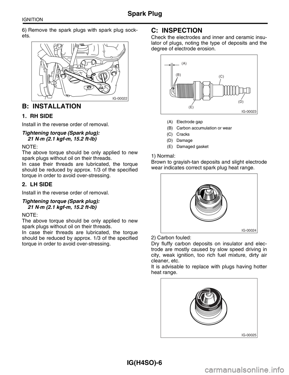
6) Remove the spark plugs with spark plug sock-
ets.
B: INSTALLATION
1. RH SIDE
Install in the reverse order of removal.
Tightening torque (Spark plug):
21 N
⋅m (2.1 kgf-m, 15.2 ft-lb)
NOTE:
The above torque should be only applied to new
spark plugs without oil on their threads.
In case their threads are lubricated, the torque
should be reduced by approx. 1/3 of the specified
torque in order to avoid over-stressing.
2. LH SIDE
Install in the reverse order of removal.
Tightening torque (Spark plug):
21 N
⋅m (2.1 kgf-m, 15.2 ft-lb)
NOTE:
The above torque should be only applied to new
spark plugs without oil on their threads.
In case their threads are lubricated, the torque
should be reduced by approx. 1/3 of the specified
torque in order to avoid over-stressing.
C: INSPECTION
Check the electrodes and inner and ceramic insu-
lator of plugs, noting the type of deposits and the
degree of electrode erosion.
1) Normal:
Brown to grayish-tan deposits and slight electrode
wear indicates correct spark plug heat range.
2) Carbon fouled:
Dry fluffy carbon deposits on insulator and elec-
trode are mostly caused by slow speed driving in
city, weak ignition, too rich fuel mixture, dirty air
cleaner, etc.
It is advisable to replace with plugs having hotter
heat range.
IG-00022
(A) Electrode gap
(B) Carbon accumulation or wear
(C) Cracks
(D) Damage
(E) Damaged gasket
IG-00023
(A)
(B)
(C)
(D)
(E)
IG-00024
IG-00025
Page 1583 of 2870

ME(H4DOTC)-123
MECHANICAL
Engine Noise
26.Engine Noise
A: INSPECTION
NOTE*:
When disconnecting the fuel injector connector, Malfunction Indicator Light illuminates and DTC is stored in
ECM memory.
Therefore, carry out the CLEAR MEMORY MODE
necting the fuel injector connector.
Type of sound Condition Possible cause
Regular clicking soundSound increases as engine
speed increases. Valve mechanism is defective.
Incorrect valve clearance
Worn valve rocker
Worn camshaft
Broken valve spring
Heavy and dull clankOil pressure is low. Worn crankshaft main bearing
Worn connecting rod bearing (big end)
Oil pressure is normal. Loose flywheel mounting bolts
Damaged engine mounting
High-pitched clank (Spark
knock)Sound is noticeable when
accelerating with an overload. Ignition timing advanced
Accumulation of carbon inside combustion chamber
Wrong heat range of spark plug
Improper octane number of gasoline
Clank when engine speed is
medium (1,000 to 2,000 rpm).Sound is reduced when fuel
injector connector of noisy cyl-
inder is disconnected.
(NOTE*) Worn crankshaft main bearing
Worn bearing at crankshaft end of connecting rod
Knocking sound when engine
is operating under idling speed
and engine is warmSound is reduced when fuel
injector connector of noisy cyl-
inder is disconnected.
(NOTE*) Worn cylinder liner and piston ring
Broken or stuck piston ring
Worn piston pin and hole at piston end of connecting rod
Sound is not reduced if each
fuel injector connector is dis-
connected in turn. (NOTE*) Unusually worn valve lifter
Worn cam gear
Worn camshaft journal bore in crankcase
Squeaky sound — Insufficient generator lubrication
Rubbing sound — Defective generator brush and rotor contact
Gear scream when starting
engine— Defective ignition starter switch
Worn gear and starter pinion
Sound like polishing glass with
a dry cloth— Loose drive belt
Defective water pump shaft
Hissing sound — Loss of compression
Air leakage in air intake system, hoses, connections or mani-
folds
Timing belt noise — Loose timing belt
Belt contacting case/adjacent part
Valve tappet noise — Incorrect valve clearance
Page 1622 of 2870

IG(H4DOTC)-6
IGNITION
Spark Plug
5) Disconnect the connector from ignition coil.
6) Remove the ignition coil.
7) Remove the spark plugs with the spark plug
sockets.
B: INSTALLATION
1. RH SIDE
Install in the reverse order of removal.
Tightening torque (Spark plug):
21 N
⋅m (2.1 kgf-m, 15.2 ft-lb)
Tightening torque (Ignition coil):
16 N
⋅m (1.6 kgf-m, 11.7 ft-lb)
NOTE:
The above torque should be only applied to new
spark plugs without oil on their threads.
In case their threads are lubricated, the torque
should be reduced by approx. 1/3 of the specified
torque in order to avoid over-stressing.
2. LH SIDE
Install in the reverse order of removal.
Tightening torque (Spark plug):
21 N
⋅m (2.1 kgf-m, 15.2 ft-lb)
Tightening torque (Ignition coil):
16 N
⋅m (1.6 kgf-m, 11.7 ft-lb)
NOTE:
The above torque should be only applied to new
spark plugs without oil on their threads.
In case their threads are lubricated, the torque
should be reduced by approx. 1/3 of the specified
torque in order to avoid over-stressing.
C: INSPECTION
Check the electrodes and inner and ceramic insu-
lator of plugs, noting the type of deposits and the
degree of electrode erosion.
1) Normal:
Brown to grayish-tan deposits and slight electrode
wear indicates correct spark plug heat range.
FU-01308
IG-00008
IG-00009
(A) Electrode gap
(B) Carbon accumulation or wear
(C) Cracks
(D) Damage
(E) Damaged gasket
IG-00010
(A)
(B)
(C)
(D)
(E)
IG-00011
Page 1665 of 2870

EN(H4DOTC)-35
ENGINE (DIAGNOSTIC)
Subaru Select Monitor
NOTE:
For detailed operation procedure, refer to the “SUBARU SELECT MONITOR OPERATION MANUAL”.
5. READ CURRENT DATA FOR ENGINE (OBD MODE)
1) On the «Main Menu» display screen, select the {Each System Check} and press the [YES] key.
2) On the «System Selection Menu» display screen, select the {Engine} and press the [YES] key.
3) Press the [YES] key after the information of engine type was displayed.
4) On the «Engine Diagnosis» display screen, select the {OBD System} and press the [YES] key.
5) On the «OBD Menu» screen, select the {Current Data Display/Save}, and then press the [YES] key.
6) On the «Data Display Menu» screen, select the {Data Display} and press the [YES] key.
7) Using the scroll key, move the display screen up or down until the desired data is shown.
A list of the support data is shown in the following table.
Air conditioning signal A/C Compressor Signal ON or OFF
Radiator main fan relay signal Radiator Fan Relay #1 ON or OFF
Knocking signal Knocking Signal ON or OFF
Radiator sub fan relay signal Radiator Fan Relay #2 ON or OFF
Power steering switch signal P/S Switch ON or OFF
Engine torque control permission signal Torque Permission Signal ON or OFF
Rear oxygen sensor rich signal Rear Oxygen Rich Signal ON or OFF
Starter switch signal Starter Switch ON or OFF
Idle switch signal Idle Switch ON or OFF
Crankshaft position sensor signal Crankshaft Position Sig. ON or OFF
Camshaft position sensor signal Camshaft Position Sig. ON or OFF
Rear defogger switch signal Rear Defogger SW ON or OFF
Blower fan switch signal Blower Fan SW ON or OFF
Small light switch signal Light Switch ON or OFF
Tumble generated valve output signal TGV Output ON or OFF
Exhaust temperature signal Exhaust Gas Temperature°C
Estimated cumulative driving distance Odd Meter km
Roughness Monitor for #1 cylinder Roughness Monitor #1 —
Roughness Monitor for #2 cylinder Roughness Monitor #2 —
Roughness Monitor for #3 cylinder Roughness Monitor #3 —
Roughness Monitor for #4 cylinder Roughness Monitor #4 —
Wiper switch signal Wiper Switch ON or OFF
A/C middle pressure switch signal A/C Mid pressure switch ON or OFF
AT retard angle demand signal Retard Signal from AT ON or OFF
AT fuel cut demand signal Fuel Cut Signal from AT ON or OFF
Description Display Unit of measure
Number of diagnosis code Number of Diag. Code —
Condition of malfunction indicator light MI (MIL) ON or OFF
Monitoring test of misfire Misfire monitoring Complete or incomplete
Monitoring test of fuel system Fuel system monitoring Complete or incomplete
Monitoring test of comprehensive component Component monitoring Complete or incomplete
Test of catalyst Catalyst Diagnosis Complete or incomplete
Test of heating-type catalyst Heated catalyst No support
Test of evaporative emission purge control system Evaporative purge system No support
Test of secondary air system Secondary air system No support
Test of air conditioning system refrigerant A/C system refrigerant No support
Test of oxygen sensor Oxygen sensor Complete or incomplete
Test of oxygen sensor heater Oxygen Heater Diagnosis Complete or incomplete
Test of EGR system EGR system No supportRemarks Display Unit of measure