2004 SUBARU FORESTER engine oil
[x] Cancel search: engine oilPage 22 of 2870

AC-20
HVAC SYSTEM (HEATER, VENTILATOR AND A/C)
General Description
C: CAUTION
1. HFC-134a A/C SYSTEM
The cooling system components for the HFC-
134a system such as the refrigerant and compres-
sor oil are different from the old conventional HFC-
12 system components and they are incompatible
with each other.
Vehicles with the HFC-134a system can be iden-
tified by the label (A) attached to the vehicle.
Before maintenance, check which A/C system is in-
stalled in the vehicle.
2. COMPRESSOR OIL
HFC-134a compressor oil has no compatibility
with that for R12 system.
Use only the manufacturer-authorized compres-
sor oil for the HFC-134a system; only use
ZXL200PG.
Do not mix multiple compressor oils.
If HFC-12 compressor oil is used in a HFC-134a A/
C system, the compressor may become stuck due
to poor lubrication, or the refrigerant may leak due
to swelling of rubber parts.
On the other hand, if HFC-134a compressor oil is
used in a HFC-12 A/C system, the durability of the
A/C system will be lowered.
HFC-134a compressor oil is very hygroscopic.
When replacing or installing/removing A/C parts,
immediately isolate the oil from the atmosphere us-
ing a plug or tape. In order to avoid moisture, store
the oil in a container with its cap securely closed.
3. REFRIGERANT
The HFC-12 refrigerant cannot be used in the
HFC-134a A/C system. The HFC-134a refrigerant,
also, cannot be used in the HFC-12 A/C system.
If an incorrect or no refrigerant is used, poor lu-
brication will result and the compressor itself may
be damaged.
4. HANDLING OF REFRIGERANT
The refrigerant boils at approx. −30°C (−22°F).
When handling it, be sure to wear safety goggles
and protective gloves. Direct contact of the refriger-
ant with skin may cause frostbite.
If the refrigerant gets into your eye, avoid rubbing
your eyes with your hands. Wash your eye with
plenty of water, and receive medical treatment from
an eye doctor.
Do not heat a service can. If a service can is di-
rectly heated, or put into boiling water, the inside
pressure will become extremely high. This may
cause the can to explode. If a service can must be
warmed up, use hot water in 40°C (104°F) max.
Do not drop or impact a service can. (Observe
the precautions and operation procedure described
on the refrigerant can.)
When the engine is running, do not open the
high-pressure valve of the manifold gauge. The
high-pressure gas will back-flow resulting in an ex-
plosion of the can.
Provide good ventilation and do not work in a
closed area.
In order to prevent global warming, avoid releas-
ing HFC-134a into the atmosphere. Using a refrig-
erant recovery system, discharge and reuse it.
AC-00006
(A)
(A) Goggles
(B) Gloves
(C) Avoid open flame
(D) No direct heat on container
(E) Do not discharge
(F) Loosen
(A)
(B)
(C) (D)
(E) (F)
AC-00007
Page 28 of 2870

AC-26
HVAC SYSTEM (HEATER, VENTILATOR AND A/C)
Refrigerant Recovery Procedure
3. Refrigerant Recovery Proce-
dure
A: OPERATION
CAUTION:
During operation, be sure to wear safety gog-
gles and protective gloves.
Connect the refrigerant recovery system with
the manifold gauge set to discharge the refrig-
erant from the A/C system and reuse it.
When reusing the discharged refrigerant, keep
service cans on hand. Because the discharge
rate with the recovery system is approx. 90%, ser-
vice cans are necessary to charge the refrigerant.
Follow the detailed operation procedure de-
scribed in the operation manual attached to the
refrigerant recovery system.
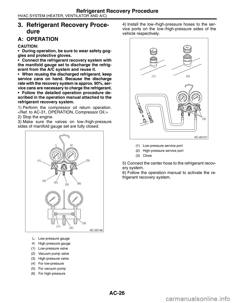
1) Perform the compressor oil return operation.
2) Stop the engine.
3) Make sure the valves on low-/high-pressure
sides of manifold gauge set are fully closed.4) Install the low-/high-pressure hoses to the ser-
vice ports on the low-/high-pressure sides of the
vehicle respectively.
5) Connect the center hose to the refrigerant recov-
ery system.
6) Follow the operation manual to activate the re-
frigerant recovery system.
L: Low-pressure gauge
H: High-pressure gauge
(1) Low-pressure valve
(2) Vacuum pump valve
(3) High-pressure valve
(4) For low-pressure
(5) For vacuum pump
(6) For high-pressure
AC-00146
(2) (4)
(5)(6)
(3)(3)
(2) (1)H L
(1)
(1) Low-pressure service port
(2) High-pressure service port
(3) Close
AC-00147
(3) (2) (1)
Page 32 of 2870

AC-30
HVAC SYSTEM (HEATER, VENTILATOR AND A/C)
Refrigerant Leak Check
5. Refrigerant Leak Check
A: INSPECTION
1) Operate the A/C system for approx. 10 minutes,
and confirm that the high-pressure side shows at
least 690 kPa (7.03 kg/cm
2, 100 psi). Then stop the
engine to start the leak test.
2) Starting from the connection between the high-
pressure pipe and evaporator, check the system for
leaks along the high-pressure side through the
compressor. The following items must be checked
thoroughly.
3) Check the joint and seam between the pressure
switch (triple pressure switch) and high-pressure
pipe.
4) Check the connections between the condenser
and pipes, and welded joints on the condenser.
The leak tester may detect the oil on the condenser
fins as a leak.
5) Check the joint between the compressor and
hoses.
6) Check the machined area of compressor and
other joints on the compressor.
7) Check the compressor shaft seal at the area
near the center of compressor clutch pulley.
Some shaft seals show a slight amount of leakage
about 28 g (1.0 oz) per year. This is not a problem.
8) Starting from the connection between the low-
pressure pipe and evaporator, check the system for
leakage along the low-pressure side through the
compressor. The following items must be checked
thoroughly.
Connection between two parts
Connection between the pipe and plate
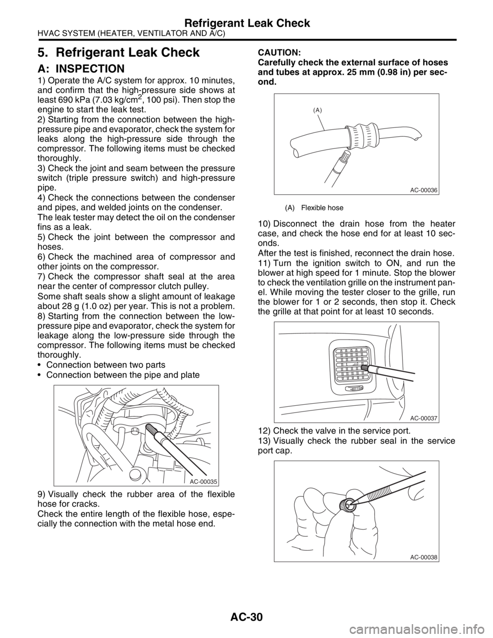
9) Visually check the rubber area of the flexible
hose for cracks.
Check the entire length of the flexible hose, espe-
cially the connection with the metal hose end.CAUTION:
Carefully check the external surface of hoses
and tubes at approx. 25 mm (0.98 in) per sec-
ond.
10) Disconnect the drain hose from the heater
case, and check the hose end for at least 10 sec-
onds.
After the test is finished, reconnect the drain hose.
11) Turn the ignition switch to ON, and run the
blower at high speed for 1 minute. Stop the blower
to check the ventilation grille on the instrument pan-
el. While moving the tester closer to the grille, run
the blower for 1 or 2 seconds, then stop it. Check
the grille at that point for at least 10 seconds.
12) Check the valve in the service port.
13) Visually check the rubber seal in the service
port cap.
AC-00035
(A) Flexible hose
AC-00036
(A)
AC-00037
AC-00038
Page 33 of 2870

AC-31
HVAC SYSTEM (HEATER, VENTILATOR AND A/C)
Compressor Oil
6. Compressor Oil
A: OPERATION
NOTE:
Before making repairs, conduct the oil return oper-
ation to return the compressor oil in circulation with
the refrigerant to the compressor.
1) Increase the engine speed to 1,500 rpm.
2) Turn ON the A/C switch.
3) Turn the temperature control dial to MAX COOL.
4) Set the air inlet select switch to RECIRC posi-
tion.
5) Turn the fan dial to HI.
6) Leave in this condition for 10 minutes.
B: REPLACEMENT
NOTE:
If a component is replaced, add an appropriate
amount of compressor oil (same as the amount of
remaining oil in removed component).
When replacing the compressor, the new com-
pressor will already have the specified amount of
oil in it. Install the new compressor after removing
the same amount of oil that is remaining in the com-
pressor removed.
Replacement parts Amount of oil replenishment
EvaporatorApprox. 50 cm
3
(1.7 US fl oz, 1.8 Imp fl oz)
CondenserApprox. 30 cm
3
(1.0 US fl oz, 1.1 Imp fl oz)
HoseApprox. 10 cm
3
(0.4 US fl oz, 0.4 Imp fl oz)
Receiver dryerApprox. 10 cm
3
(0.4 US fl oz, 0.4 Imp fl oz)
Page 38 of 2870

AC-36
HVAC SYSTEM (HEATER, VENTILATOR AND A/C)
Compressor
11.Compressor
A: INSPECTION
1. MAGNETIC CLUTCH CLEARANCE
1) Check the clearance of the entire circumference
around the drive plate and pulley.
Standard:
0.3 — 0.6 mm (0.0118 — 0.0236 in)
2. MAGNETIC CLUTCH OPERATION
1) Disconnect the compressor connector.
2) Connect the battery positive (+) terminal to the
No. 3 terminal of the compressor connector.
3) Make sure the magnet clutch engages.
If NG, replace the compressor.
B: REMOVAL
1) Perform the compressor oil return operation.
2) Turn the A/C switch OFF and stop the engine.
3) Using the refrigerant recovery system, discharge
refrigerant.
4) Disconnect the ground cable from battery.
5) Remove the V-belt.
6) Remove the generator.
7) Remove the low-pressure hose and high-pres-
sure hose.
8) Disconnect the compressor harness from body
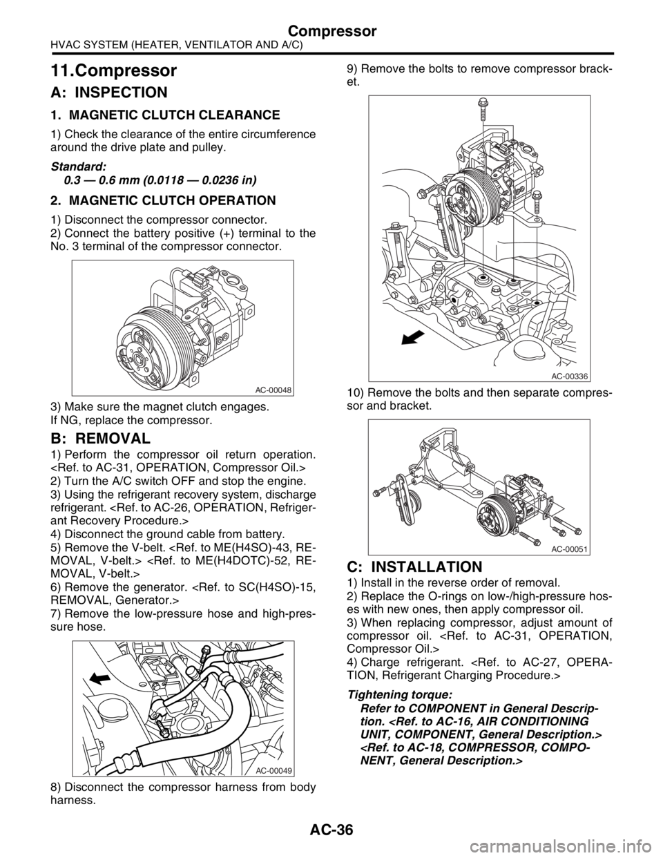
harness.9) Remove the bolts to remove compressor brack-
et.
10) Remove the bolts and then separate compres-
sor and bracket.
C: INSTALLATION
1) Install in the reverse order of removal.
2) Replace the O-rings on low-/high-pressure hos-
es with new ones, then apply compressor oil.
3) When replacing compressor, adjust amount of
compressor oil.
4) Charge refrigerant.
Tightening torque:
Refer to COMPONENT in General Descrip-
tion.
AC-00048
AC-00049
AC-00336
AC-00051
Page 313 of 2870

ET-3
ENTERTAINMENT
Radio System
2. Radio System
A: WIRING DIAGRAM
1. RADIO
B: INSPECTION
Symptom Repair order
No power coming in. (No display and no sound from speakers.) (1) Check the fuse and power supply for radio.
(2) Check the radio ground.
(3) Remove the radio for repair.
A specific speaker does not operate. (1) Check the speaker.
(2) Check the output circuit between radio and speaker.
Radio generates noise with engine running. (1) Check the radio ground.
(2) Check the generator.
(3) Check the ignition coil.
(4) Remove the radio for repair.
AM and FM modes are weak or noisy. (1) Check the antenna.
(2) Check the antenna amplifier.
(3) Check the noise suppressor.
(4) Check the radio ground.
(5) Remove the radio for repair.
Page 693 of 2870

SPC-4
SPECIFICATION
Forester
F: SUSPENSION
G: BRAKE
★: RHD model
H: TIRE
I: CAPACITY
★1: With oil pump★2: MT model with oil cooler Included★3: Model with ATF warmer Front Macpherson strut type, Independent, Coil spring
Rear Dual-link type, Independent, Coil spring
Model 2.0 L Non-turbo, 2.5 L Non-turbo
2.0 L Turbo, 2.5 L Non-turbo
★, 2.5 L Non-turbo
Service brake system Dual circuit hydraulic with vacuum suspended power unit
Front Ventilated disc brake
Rear Drum brake Disc brake
Parking brake Mechanical on rear brakes
Rim size 15×6J 16×6 1/2J
Tire size 205/70 R15 95H 215/60 R16 95V, P215/60 R16 94H
Type Steel belted radial, Tubeless
Model 2.0 L Non-turbo 2.0 L Turbo 2.5 L Non-turbo 2.5 L Turbo
Tr a n s m i s s i o n 5 M T 4 AT 5 M T 4 AT 5 M T 4 AT 5 M T 4 AT
Fuel tank2 (US gal, Imp gal) 60 (15.9, 13.2)
Engine oil
(When
replacing)2 (US qt, Imp qt) Approx. 4.0 (4.2, 3.5)
Tr a n s m i s -
sion gear oil2 (US qt, Imp qt)4.0
(4.2, 3.5)—3.5
(3.7, 3.1),
3.9
(4.1, 3.4)
★1
—4.0
(4.2, 3.5)—3.5
(3.7, 3.1)—
AT F2 (US qt, Imp qt) —8.4
(8.9, 7.4)—9.3
(9.8, 8.2)—9.3
(9.8, 8.2)—9.3
(9.8, 8.2)
Front differ-
ential gear
oil2 (US qt, Imp qt) —1.2
(1.3, 1.1)—1.2
(1.3, 1.1)—1.2
(1.3, 1.1)—1.2
(1.3, 1.1)
Rear differ-
ential gear
oil2 (US qt, Imp qt) 0.8 (0.8, 0.6)
Pow er
steering
fluid2 (US qt, Imp qt) 0.7 (0.7, 0.6)
Engine
coolant2 (US qt, Imp qt)6.6
(7.0, 5.8)6.5
(6.9, 5.7),
6.9
(7.3, 6.1)
★3
7.4
(7.8, 6.5)7.3
(7.7, 6.4)
★2
6.9
(7.3, 6.1)6.8
(7.2, 6.0)7.4
(7.8, 6.5)7.3
(7.7, 6.4)
Page 717 of 2870

RM-2
RECOMMENDED MATERIAL
Recommended Materials
1. Recommended Materials
A: RECOMMENDED MATERIALS
1. GENERAL
To insure the best performance, always use the
specified oil, gasoline, adhesive, sealant, etc. or a
substitute of equivalent quality.
2. FUEL
Always use a gasoline of the same or higher octane
value than specified in the owner’s manual. Ignor-
ing the specifications below will result in damage or
poor operation of the engine and fuel injection sys-
tem. Use the specified gasoline to correct perfor-
mance.
Unleaded gasoline
Use unleaded gasoline and not leaded gasoline on
vehicles with catalytic converter installed to reduce
air pollution. Using leaded gasoline will damage the
catalytic converter.
*For Australia model.
Leaded gasoline
On vehicles without catalytic converter, use leaded
gasoline with an octane value of 90 RON or higher.
Model Petrol RON
Non-turbo UnleadedMore than 95 RON
More than 90 RON
*
Turbo Unleaded More than 98 RON