Page 33 of 2870

AC-31
HVAC SYSTEM (HEATER, VENTILATOR AND A/C)
Compressor Oil
6. Compressor Oil
A: OPERATION
NOTE:
Before making repairs, conduct the oil return oper-
ation to return the compressor oil in circulation with
the refrigerant to the compressor.
1) Increase the engine speed to 1,500 rpm.
2) Turn ON the A/C switch.
3) Turn the temperature control dial to MAX COOL.
4) Set the air inlet select switch to RECIRC posi-
tion.
5) Turn the fan dial to HI.
6) Leave in this condition for 10 minutes.
B: REPLACEMENT
NOTE:
If a component is replaced, add an appropriate
amount of compressor oil (same as the amount of
remaining oil in removed component).
When replacing the compressor, the new com-
pressor will already have the specified amount of
oil in it. Install the new compressor after removing
the same amount of oil that is remaining in the com-
pressor removed.
Replacement parts Amount of oil replenishment
EvaporatorApprox. 50 cm
3
(1.7 US fl oz, 1.8 Imp fl oz)
CondenserApprox. 30 cm
3
(1.0 US fl oz, 1.1 Imp fl oz)
HoseApprox. 10 cm
3
(0.4 US fl oz, 0.4 Imp fl oz)
Receiver dryerApprox. 10 cm
3
(0.4 US fl oz, 0.4 Imp fl oz)
Page 104 of 2870

AB-4
AIRBAG SYSTEM
General Description
Do not drop the airbag modulator parts, subject
them to high temperature over 93°C (199°F), or let
water, oil, or grease get on them; otherwise, the in-
ternal parts may be damaged and reliability greatly
lowered.
If any damage, opening, or rust is found on the
airbag system wire harness, do not attempt to re-
pair using soldering equipment. Be sure to replace
the faulty harness with a new genuine part.
Install the wire harness securely with the speci-
fied clips to avoid interference or tangled up with
other parts. Do not allow water or oil to come in contact with
the connector terminals. Do not touch the connec-
tor terminals.
Either of the airbag modules for driver, passen-
ger or side, or pretensioner must not be disassem-
bled.
The removed front seat with the airbag module
must be kept at least 200 mm (8 in) away from walls
and other objects.
Do not use the airbag or pretensioner parts from
other vehicles. Always replace defective parts with
new ones.
Never reuse a deployed airbag or pretensioner.
When painting or performing sheet metal work
on the front part of the vehicle, including the front
wheel apron, front fender, and front side frame, re-
move the front sub sensors and wire harness of the
airbag system.
AB-00123
AB-00124
AB-00125
(1) More than 200 mm (8 in)
AB-00126
AB-00779
AB-00128
(1)
Page 136 of 2870

AB-4
AIRBAG SYSTEM (DIAGNOSTIC)
General Description
3. General Description
A: CAUTION
When servicing a vehicle, be sure to turn the ig-
nition switch to OFF, disconnect the ground cable
from battery, and wait for more than 20 seconds
before starting work.
The airbag system is fitted with a backup power
source. If the airbag system is serviced within 20
seconds after the ground cable is disconnected, it
may inflate.
If sensors, airbag module, airbag control module,
pretensioner, and harness are deformed or dam-
aged, replace them with new genuine parts.
Do not use the airbag system and pretensioners
on other vehicles. When replacing parts, be sure to
replace them with new parts.
When checking the system, be sure to use a dig-
ital circuit tester. Use of an analog circuit tester may
cause the airbag to activate erroneously. When checking, use a test harness. Do not di-
rectly apply the tester probe to any connector termi-
nal of the airbag.
Do not drop the airbag modulator parts, subject
them to high temperature over 93°C (199°F), or let
water, oil, or grease get on them; otherwise, the in-
ternal parts may be damaged and reliability greatly
lowered.
AB-00002
AB-00120
AB-00121
(1) Test harness
AB-00122
(1)
AB-00123
Page 270 of 2870

LI-16
LIGHTING SYSTEM
Headlight Bulb
12.Headlight Bulb
A: REMOVAL
CAUTION:
Because the halogen bulb operates at a high
temperature, dirt and oil on the bulb surface re-
duces the bulb’s service life. Hold the flange
portion when replacing the bulb. Never touch
the glass portion.
Do not leave the headlight without a bulb for
a long time. Dust, moisture, etc. entering the
headlight may affect its performance.
1) Disconnect the ground cable from battery.
2) Remove the air intake duct (when removing the
headlight RH).
3) Disconnect the harness connector.
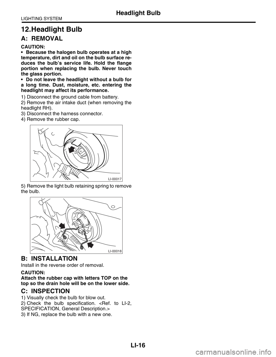
4) Remove the rubber cap.
5) Remove the light bulb retaining spring to remove
the bulb.
B: INSTALLATION
Install in the reverse order of removal.
CAUTION:
Attach the rubber cap with letters TOP on the
top so the drain hole will be on the lower side.
C: INSPECTION
1) Visually check the bulb for blow out.
2) Check the bulb specification.
SPECIFICATION, General Description.>
3) If NG, replace the bulb with a new one.
LI-00017
LI-00018
Page 386 of 2870

IDI-2
INSTRUMENTATION/DRIVER INFO
General Description
1. General Description
A: SPECIFICATION
B: CAUTION
Be careful not to damage meters and instrument panel.
Be careful not to damage meter glasses.
Make sure that electrical connector is connected securely.
After installation, make sure that each meter operates normally.
Use gloves to avoid damage and getting fingerprints on the glass surface and meter surfaces.
Do not apply excessive force to the printed circuit.
Do not drop or otherwise apply impact.
C: PREPARATION TOOL
1. GENERAL TOOL
Combination meterSpeedometer Electric pulse type
Temperature gauge Cross coil type
Fuel gauge Cross coil type
Tachometer Electric pulse type
Turn signal indicator light 14 V — 2 W
Charge indicator light 14 V — 1.4 W
Oil pressure indicator light LED
ABS warning light 14 V — 1.4 W
Malfunction indicator light LED
HI-beam indicator light 14 V — 2 W
Door open warning light LED
Seat belt warning light LED
Brake fluid and parking brake warning
light14 V — 2 W
FWD indicator light LED
AIRBAG warning light LED
Meter illumination light 14 V — 3.4 W, 14 V — 2 W
AT OIL TEMP. warning light LED
LO indicator light LED
HOLD indicator light LED
Immobilizer indicator light LED
Rear differential oil temperature warn-
ing light14 V — 2 W
Cruise indicator light 14 V — 1.4 W
Rear fog light indicator light 14 V — 2 W
POWER indicator light 14 V — 1.4 W
Low fuel warning light LED
AT select lever position indicator light 14 V — 100 mA
LCD back light 14 V — 1.4 W
TOOL NAME REMARKS
Circuit tester Used for measuring resistance and voltage.
Page 396 of 2870
IDI-12
INSTRUMENTATION/DRIVER INFO
Combination Meter Assembly
1. BULB REPLACEMENT
D: ASSEMBLY
Assemble in the reverse order of disassembly.
(1) Charge warning
(2) Tachometer
(3) Speedometer and tachometer
(4) Rear fog light indicator light
(5) HI-beam indicator
(6) Turn signal indicator RH
(7) Speedometer
(8) Turn signal indicator LH
(9) Cruise indicator light or rear differential oil tem-
perature warning light
(10) Brake warning
(11) ABS warning
(12) AT power mode indicator light
(13) Fuel gauge
(14) Temperature gauge
(15) LCD (Outside temperature indicator, Odometer
and tripmeter)
IDI00024(1) (2)(3)(5)
(6)
(7)(8)
(9)
(10)
(11)
(13)
(14)
(15)
(4)
(12)
Page 501 of 2870

EI-25
EXTERIOR/INTERIOR TRIM
Front Bumper
C: REPAIR
1. COATING METHOD FOR PP BUMPER
Pro-
cess
No.Process name Job contents
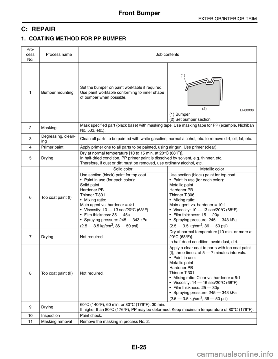
1 Bumper mountingSet the bumper on paint worktable if required.
Use paint worktable conforming to inner shape
of bumper when possible.
(1) Bumper
(2) Set bumper section
2MaskingMask specified part (black base) with masking tape. Use masking tape for PP (example, Nichiban
No. 533, etc.).
3Degreasing, clean-
ingClean all parts to be painted with white gasoline, normal alcohol, etc. to remove dirt, oil, fat, etc.
4 Primer paint Apply primer one to all parts to be painted, using air gun. Use primer (clear).
5DryingDry at normal temperature [10 to 15 min. at 20°C (68°F)].
In half-dried condition, PP primer paint is dissolved by solvent, e.g. thinner, etc.
Therefore, if dust or dirt must be removed, use ordinary alcohol, etc.
6 Top coat paint (I)Solid color Metallic color
Use section (block) paint for top coat.
Paint in use (for each color):
Solid paint
Hardener PB
Thinner T-301
Mixing ratio:
Main agent vs. hardener = 4:1
Viscosity: 10 — 13 sec/20°C (68°F)
Film thickness: 35 — 45µ
Spraying pressure: 245 — 343 kPa
(2.5 — 3.5 kg/cm
2, 36 — 50 psi)Use section (block) paint for top coat.
Paint in use (for each color):
Metallic paint
Hardener PB
Thinner T-306
Mixing ratio:
Main agent vs. hardener = 10:1
Viscosity: 10 — 13 sec/20°C (68°F)
Film thickness: 15 — 20µ
Spraying pressure: 245 — 343 kPa
(2.5 — 3.5 kg/cm2, 36 — 50 psi)
7 Drying Not required.Dry at normal temperature [10 min. or more at
20°C (68°F)].
In half-dried condition, avoid dust, dirt.
8 Top coat paint (II) Not required.Apply a clear coat to parts with top coat paint
(I), three times, at 5 — 7 minutes intervals.
Paint in use:
Metallic paint
Hardener PB
Thinner T-301
Mixing ratio: Clear vs. hardener = 6:1
Viscosity: 14 — 16 sec/20°C (68°F)
Film thickness: 25 — 30µ
Spraying pressure: 245 — 343 kPa
(2.5 — 3.5 kg/cm
2, 36 — 50 psi)
9Drying60°C (140°F), 60 min. or 80°C (176°F), 30 min.
If higher than 80°C (176°F), PP may be deformed. Keep maximum temperature of 80°C (176°F).
10 Inspection Paint check.
11 Masking removal Remove the masking in process No. 2.
EI-00038
(1)
(2)
Page 719 of 2870
RM-4
RECOMMENDED MATERIAL
Recommended Materials
SAE viscosity No. and applicable temperature
Engine oil
Non-turbo model
Tu r b o m o d e l
RM-00032 (˚F) –22 –4 14 50 68 86 104 (˚C) –30 –20 –10 0 10 20 30 40
5W-30
32
10W-30 or 10W-40
0W-20 Recommend
RM-00033 (˚F)–22–4 14 50 68 86 104 (˚C)–30–20 –100
10 20 30 40
5W-30 Recommend
32
10W-30 or 10W-40