2004 SUBARU FORESTER oil temperature
[x] Cancel search: oil temperaturePage 957 of 2870
ME(H4SO)-86
MECHANICAL
Cylinder Block
NOTE:
Immediately after reboring, the cylinder diameter
may differ from its real diameter due to temperature
rise. Thus, pay attention to this when measuring
the cylinder diameter.
Limit of cylinder enlarging (boring):
0.5 mm (0.020 in)
3. PISTON AND PISTON PIN
1) Check the pistons and piston pins for damage,
cracks, and wear and the piston ring grooves for
wear and damage. Replace if defective.
2) Measure the piston-to-cylinder clearance at
each cylinder.
any of the clearances is not to specification, re-
place the piston or bore the cylinder to use an over-
size piston.
3) Make the sure that piston pin can be inserted
into piston pin hole with a thumb at 20°C (68°F).
Replace if defective.
Standard clearance between piston pin and
hole in piston:
Standard
0.004 — 0.008 mm (0.0002 — 0.0003 in)
Limit
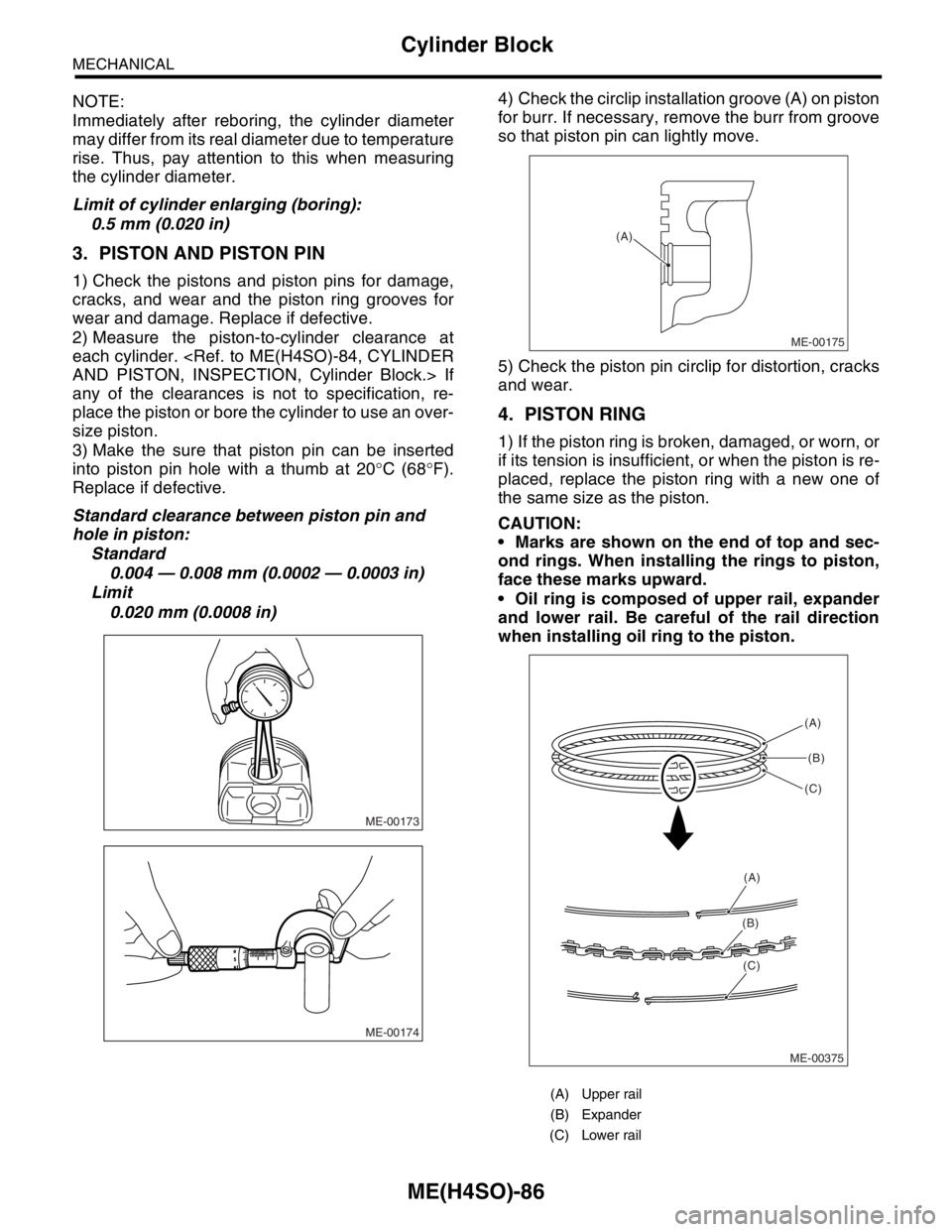
0.020 mm (0.0008 in)4) Check the circlip installation groove (A) on piston
for burr. If necessary, remove the burr from groove
so that piston pin can lightly move.
5) Check the piston pin circlip for distortion, cracks
and wear.
4. PISTON RING
1) If the piston ring is broken, damaged, or worn, or
if its tension is insufficient, or when the piston is re-
placed, replace the piston ring with a new one of
the same size as the piston.
CAUTION:
Marks are shown on the end of top and sec-
ond rings. When installing the rings to piston,
face these marks upward.
Oil ring is composed of upper rail, expander
and lower rail. Be careful of the rail direction
when installing oil ring to the piston.
ME-00173
ME-00174
(A) Upper rail
(B) Expander
(C) Lower rail
ME-00175
(A)
ME-00375(A)
(B)
(C)
(A)
(B)
(C)
Page 985 of 2870

CO(H4SO)-2
COOLING
General Description
1. General Description
A: SPECIFICATION
ModelNon-turbo Turbo
Cooling system Electric fan+Forced engine coolant circulation system
Total engine coolant capacity2(US qt, Imp qt)2.0L with ATF warmer:
Approx. 6.9 (7.29, 6.07)
2.0L AT:
Approx. 6.5 (6.87, 5.72)
2.0L MT:
Approx. 6.6 (6.98, 5.81)
2.5L AT:
Approx. 6.8 (7.19, 5.98)
2.5L MT:
Approx. 6.9 (7.29, 6.07)AT :
Approx. 7.3 (7.71, 6.42)
MT with oil cooler:
Approx. 7.3 (7.71, 6.42)
MT without oil cooler:
Approx. 7.4 (7.82, 6.51)
Water pumpType Centrifugal impeller type
Discharge perfor-
mance IDischarge 202 (5.3 US gal, 4.4 Imp gal)/min.
Pump speed — Discharge
pressure760 rpm — 2.9 kPa (0.3 mAq)
Engine coolant temperature 85°C (185°F)
Discharge perfor-
mance IIDischarge 1002 (26.4 US gal, 22.0 Imp gal)/min.
Pump speed — Discharge
pressure3,000 rpm — 49.0 kPa (5.0 mAq)
Engine coolant temperature 85°C (185°F)
Discharge perfor-
mance IIIDischarge 2002 (52.8 US gal, 44.0 Imp gal)/min.
Pump speed — Discharge
pressure6,000 rpm — 225.4 kPa (23.0 mAq)
Engine coolant temperature 85°C (185°F)
Impeller diameter 76 mm (2.99 in)
Number of impeller vanes 8
Pump pulley diameter 60 mm (2.36 in)
Clearance between
impeller and caseStandard 0.5 — 0.7 mm (0.020 — 0.028 in)
Limit 1.0 mm (0.039 in)
“Thrust” runout of impeller end 0.5 mm (0.020 in)
ThermostatType Wax pellet type
Starts to open 80 — 84°C (176 — 183°F) 76 — 80°C (169 — 176°F)
Fully opened 95°C (203°F) 91°C (196°F)
Valve lift 9.0 mm (0.354 in) or more
Valve bore 35 mm (1.38 in)
Radiator fanMotorMain fan 70 W2.0L AT (K4
★1) : 70 W
2.0L AT (EC, EK★1) :
120 W
2.0 L MT: 70 W
2.5 L: 120 W
Sub fan 70 W2.0L AT (K4
★1) : 70 W
2.0L AT (EC, EK★1) :
120 W
2.0 L MT: 70 W
2.5 L: 120 W
Fan diameter×Blade320 mm (11.81 in)×5 (main fan)
320 mm (11.81 in)×7 (sub fan)
Page 1026 of 2870

CO(H4SO)-43
COOLING
Engine Cooling System Trouble in General
12.Engine Cooling System Trouble in General
A: INSPECTION
Trouble Possible cause Corrective action
Over-heatinga. Insufficient engine coolantReplenish the engine coolant, inspect for leakage, and
repair.
b. Loose timing belt Repair or replace the timing belt tensioner.
c. Oil on drive belt Replace.
d. Malfunction of thermostat Replace.
e. Malfunction of water pump Replace.
f. Clogged engine coolant passage Clean.
g. Improper ignition timingInspect and repair the ignition control system.
h. Clogged or leaking radiator Clean or repair, or replace.
i. Improper engine oil in engine coolant Replace the engine coolant.
j. Air/fuel mixture ratio too leanInspect and repair the fuel injection system.
k. Excessive back pressure in exhaust system Clean or replace.
l. Insufficient clearance between piston and cylinder Adjust or replace.
m. Slipping clutch Repair or replace.
n. Dragging brake Adjust.
o. Defective thermostat Replace.
p. Malfunction of radiator fanInspect the radiator fan relay, engine coolant tempera-
ture sensor or radiator motor and replace there.
Over-coolinga. Atmospheric temperature extremely low Partly cover the radiator front area.
b. Defective thermostat Replace.
Engine coolant
leaks.a. Loosened or damaged connecting units on hoses Repair or replace.
b. Leakage from water pump Replace.
c. Leakage from water pipe Repair or replace.
d. Leakage around cylinder head gasket Retighten the cylinder head bolts or replace gasket.
e. Damaged or cracked cylinder head and crankcase Repair or replace.
f. Damaged or cracked thermostat case Repair or replace.
g. Leakage from radiator Repair or replace.
Noisea. Defective drive belt Replace.
b. Defective radiator fan Replace.
c. Defective water pump bearing Replace the water pump.
d. Defective water pump mechanical seal Replace the water pump.
Page 1039 of 2870
LU(H4SO)-11
LUBRICATION
Engine Oil
6) Tighten the engine oil drain plug after draining
engine oil.
Tightening torque:
44 N
⋅m (4.5 kgf-m, 32.5 ft-lb)
7) Install the service hole cover.
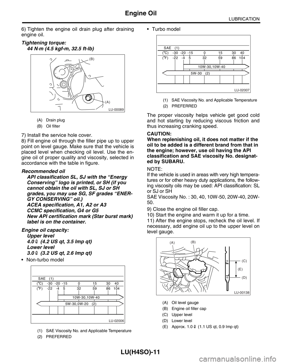
8) Fill engine oil through the filler pipe up to upper
point on level gauge. Make sure that the vehicle is
placed level when checking oil level. Use the en-
gine oil of proper quality and viscosity, selected in
accordance with the table in figure.
Recommended oil
API classification SL, SJ with the “Energy
Conserving” logo is printed, or SH (if you
cannot obtain the oil with SL, SJ or SH
grades, you may use SG, SF grades “ENER-
GY CONSERVING” oil.)
ACEA specification, A1, A2 or A3
CCMC specification, G4 or G5
New API certification mark (Star burst mark)
label is on the container.
Engine oil capacity:
Upper level
4.02 (4.2 US qt, 3.5 Imp qt)
Lower level
3.02 (3.2 US qt, 2.6 Imp qt)
Non-turbo model Turbo model
The proper viscosity helps vehicle get good cold
and hot starting by reducing viscous friction and
thus increasing cranking speed.
CAUTION:
When replenishing oil, it does not matter if the
oil to be added is a different brand from that in
the engine; however, use oil having the API
classification and SAE viscosity No. designat-
ed by SUBARU.
NOTE:
If the vehicle is used in areas with very high tempera-
tures or for other heavy duty applications, the follow-
ing viscosity oils may be used: API classification: SL
or SJ or SH
SAE Viscosity No. : 30, 40, 10W-50, 20W-40, 20W-
50.
9) Close the engine oil filler cap.
10) Start the engine and warm it up for a time.
11) After the engine stops, recheck the oil level. If
necessary, add engine oil up to the upper level on
level gauge.
(A) Drain plug
(B) Oil filter
(1) SAE Viscosity No. and Applicable Temperature
(2) PREFERRED
LU-00089
(B)
(A)
LU-02006
40 30 15 0 -15 -20 -30 ( C)
104 86 59 32
10W-30,10W-40 5 -4 -22 ( F)
SAE (1)
5W-30,0W-20 (2)
(1) SAE Viscosity No. and Applicable Temperature
(2) PREFERRED
(A) Oil level gauge
(B) Engine oil filler cap
(C) Upper level
(D) Lower level
(E) Approx. 1.02 (1.1 US qt, 0.9 Imp qt)
LU-02007
40 30 15 0 -15 -20 -30 ( C)
104 86 59 32 5 -4 -22 ( F)
SAE (1)
10W-30,10W-40
5W-30 (2)
LU-00138
(A)(B)
(C)
(D) (E)
Page 1354 of 2870

EN(H4SO)-256
ENGINE (DIAGNOSTIC)
General Diagnostic Table
*1: Check ignition coil & ignitor ASSY and spark plug.
*2: Indicate the symptom occurring only in cold temperatures.
*3: Ensure the secure installation.
*4: Check fuel injector, fuel pressure regulator and fuel filter.
*5: Inspect air leak in air intake system.
*6: Adjust the accelerator cable.
2. AUTOMATIC TRANSMISSION
NOTE:
Check general diagnostics table with non-conformity symptom for automatic transmission.
6. Surging1) Intake manifold pressure sensor
2) Intake air temperature sensor
3) Manifold absolute pressure sensor
4) Engine coolant temperature sensor (*2)
5) Crankshaft position sensor (*3)
6) Camshaft position sensor (*3)
7) Fuel injection parts (*4)
8) Throttle position sensor
9) Fuel pump and fuel pump relay
7. Spark knock1) Intake manifold pressure sensor
2) Intake air temperature sensor
3) Manifold absolute pressure sensor
4) Engine coolant temperature sensor
5) Knock sensor
6) Fuel injection parts (*4)
7) Fuel pump and fuel pump relay
8. After burning in exhaust system1) Intake manifold pressure sensor
2) Intake air temperature sensor
3) Manifold absolute pressure sensor
4) Engine coolant temperature sensor (*2)
5) Fuel injection parts (*4)
6) Fuel pump and fuel pump relay Symptom Problem parts
Page 1370 of 2870
FU(H4DOTC)-15
FUEL INJECTION (FUEL SYSTEM)
Intake Manifold
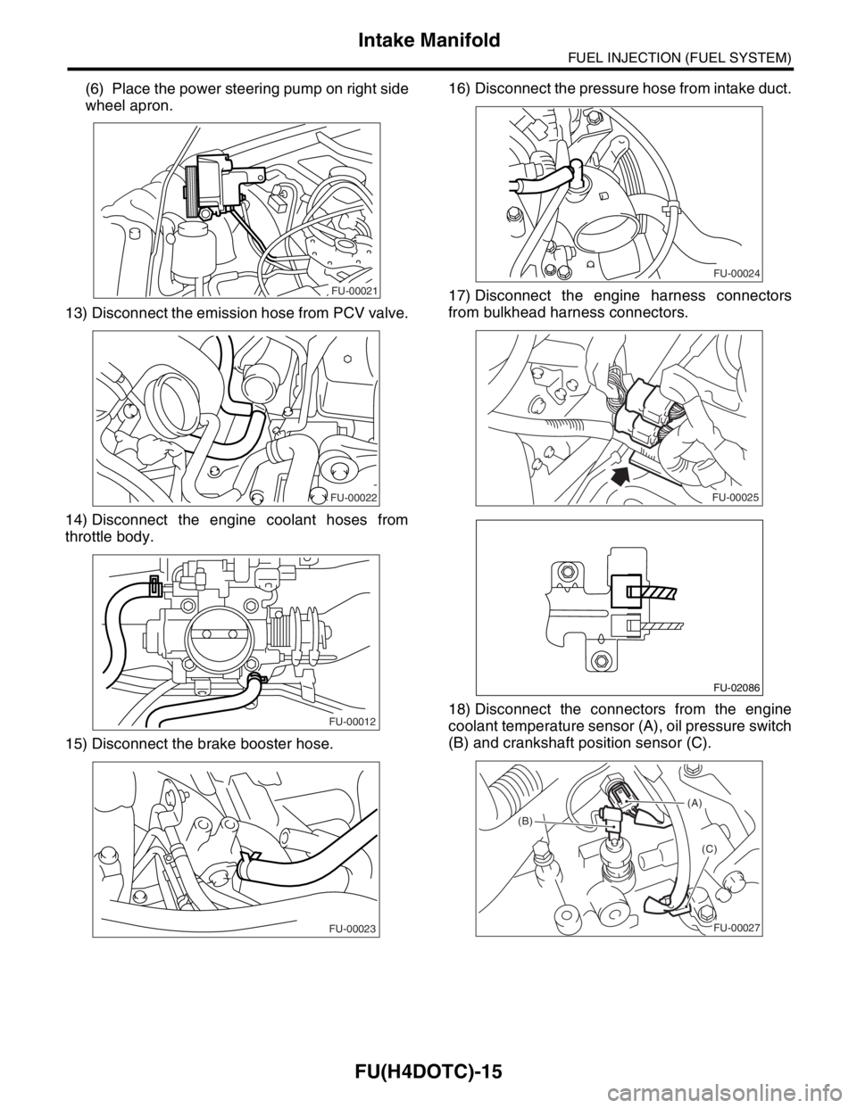
(6) Place the power steering pump on right side
wheel apron.
13) Disconnect the emission hose from PCV valve.
14) Disconnect the engine coolant hoses from
throttle body.
15) Disconnect the brake booster hose.16) Disconnect the pressure hose from intake duct.
17) Disconnect the engine harness connectors
from bulkhead harness connectors.
18) Disconnect the connectors from the engine
coolant temperature sensor (A), oil pressure switch
(B) and crankshaft position sensor (C).
FU-00021
FU-00022
FU-00012
FU-00023
FU-00024
FU-00025
FU-02086
(A)
(B)
(C)
FU-00027
Page 1373 of 2870
FU(H4DOTC)-18
FUEL INJECTION (FUEL SYSTEM)
Intake Manifold
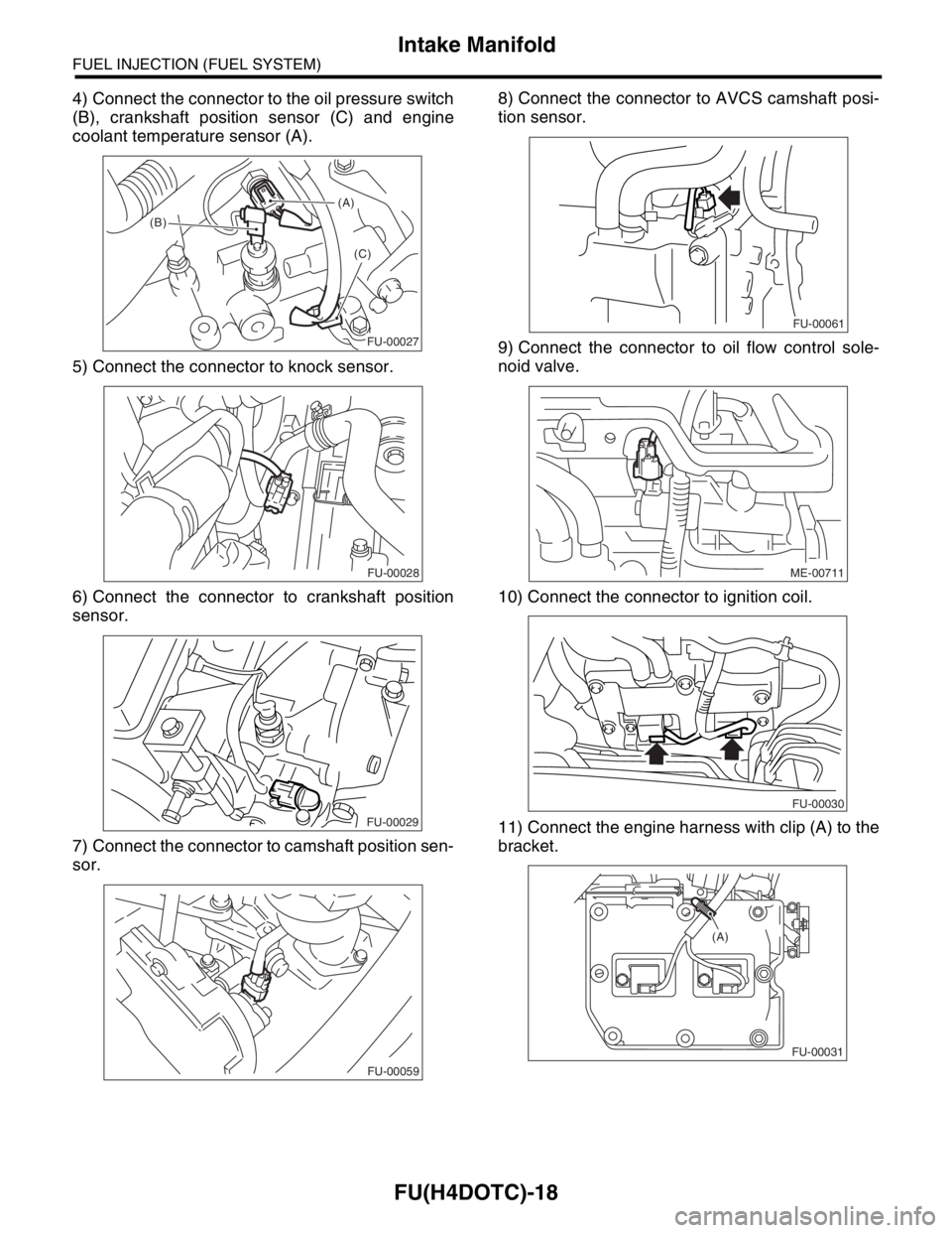
4) Connect the connector to the oil pressure switch
(B), crankshaft position sensor (C) and engine
coolant temperature sensor (A).
5) Connect the connector to knock sensor.
6) Connect the connector to crankshaft position
sensor.
7) Connect the connector to camshaft position sen-
sor.8) Connect the connector to AVCS camshaft posi-
tion sensor.
9) Connect the connector to oil flow control sole-
noid valve.
10) Connect the connector to ignition coil.
11) Connect the engine harness with clip (A) to the
bracket.
(A)
(B)
(C)
FU-00027
FU-00028
FU-00029
FU-00059
FU-00061
ME-00711
FU-00030
FU-00031
(A)
Page 1664 of 2870
![SUBARU FORESTER 2004 Service Repair Manual EN(H4DOTC)-34
ENGINE (DIAGNOSTIC)
Subaru Select Monitor
4. READ CURRENT DATA FOR ENGINE. (NORMAL MODE)
1) On the «Main Menu» display screen, select the {Each System Check} and press the [YES] key.
2](/manual-img/17/57426/w960_57426-1663.png "SUBARU FORESTER 2004 Service Repair Manual EN(H4DOTC)-34
ENGINE (DIAGNOSTIC)
Subaru Select Monitor
4. READ CURRENT DATA FOR ENGINE. (NORMAL MODE)
1) On the «Main Menu» display screen, select the {Each System Check} and press the [YES] key.
2")
EN(H4DOTC)-34
ENGINE (DIAGNOSTIC)
Subaru Select Monitor
4. READ CURRENT DATA FOR ENGINE. (NORMAL MODE)
1) On the «Main Menu» display screen, select the {Each System Check} and press the [YES] key.
2) On the «System Selection Menu» display screen, select the {Engine} and press the [YES] key.
3) Press the [YES] key after the information of engine type was displayed.
4) On the «Engine Diagnosis» screen, select the {Current Data Display/Save}, and then press the [YES] key.
5) On the «Data Display Menu» screen, select the {Data Display} and press the [YES] key.
6) Using the scroll key, move the display screen up or down until the desired data is shown.
A list of the support data is shown in the following table.
Remarks Display Unit of measure
Battery voltage Battery Voltage V
Vehicle speed signal Vehicle Speed km/h or MPH
Engine speed signal Engine Speed rpm
Engine coolant temperature signal Coolant Temp.°C or °F
Ignition timing signal Ignition Timing deg
Throttle position signal Throttle Opening Angle %
Throttle position signal Throttle Sensor Voltage V
Injection pulse width Fuel Injection #1 Pulse ms
Idle air control signal ISC Valve Duty Ratio %
generated duty control signal ALT Duty %
Fuel pump duty control signal Fuel Pump Duty %
A/F sensor current A/F Sensor #1 Current mA
A/F sensor resistance A/F Sensor #1 ResistanceΩ
Front oxygen (A/F) sensor output signal A/F Sensor #1 —
Rear oxygen sensor output signalRear O
2 Sensor
V
Short term fuel trim A/F Correction #1 %
Knock sensor correction Knocking Correction deg
Atmospheric pressure signal Atmosphere Pressure mmHg, kPa, inHg or psi
Intake manifold relative pressure signal Mani. Relative Pressure mmHg, kPa, inHg or psi
Intake manifold absolute pressure signal Mani. Absolute Pressure mmHg, kPa, inHg or psi
A/F correction (short term fuel trim) by rear oxygen sensor A/F Correction #3 %
Long term whole fuel trim A/F Learning #1 %
Canister purge control solenoid valve duty ratio CPC Valve Duty Ratio %
Primary supercharged pressure control signal Primary Control %
Tumble generated valve position sensor signal (RH side) TGV Position Sensor R V
Tumble generated valve position sensor signal (LH side) TGV Position Sensor L V
Tumble generated valve drive signal TGV Drive OPEN or CLOSE
Fuel level signal Fuel Level Voltage V
Intake air temperature signal Intake Air Temp.°C or °F
Mass air flow sensor signal Mass Air Flow g/s
Mass air flow sensor signal Air Flow Sensor Voltage V
Valve Timing Signal VVT Adv. Ang. amount R deg
Valve Timing Signal VVT Adv. Ang. amount L deg
Oil flow control solenoid valve signal OCV Duty R %
Oil flow control solenoid valve signal OCV Duty L %
Oil flow control solenoid valve current OCV current R mA
Oil flow control solenoid valve current OCV Current L mA
AT/MT identification signal AT Vehicle ID Signal AT or MT
Test Mode Signal Test Mode Signal ON or OFF
Load switch signal Electric Load Signal ON or OFF
Ignition switch signal Ignition Switch ON or OFF
Neutral position switch signal Neutral Position Switch ON or OFF
Air conditioning switch signal A/C Switch ON or OFF